Article

Design and Optimization of Origami-Inspired Orthopyramid-Like Core Panel for Load Damping

State Key Laboratory of Fluid Power and Mechatronic Systems, Zhejiang University, Hangzhou 310027, China
*
Author to whom correspondence should be addressed.
Appl. Sci. 2019, 9(21), 4619; https://doi.org/10.3390/app9214619
Submission received: 26 September 2019 / Revised: 25 October 2019 / Accepted: 27 October 2019 / Published: 30 October 2019
(This article belongs to the Section Mechanical Engineering)

Abstract

:
Core panels inspired by origami have the advantages of force allocation and energy dissipation. Used as a sandwich core, the three-dimensional panels could be created using various origami patterns. The panel is composed of the element whose structure is inspired by origami. The orthopyramid-like origami element has a tip of joined-together side triangles. Through shape deformation, it could exhibit potential mechanical performances. Owing to its deformation when collision occurs, the structure could be employed for load damping conditions. This study focuses on nine different orthopyramid-like core panels through changing the similarity parameter value and the number of edges. The experiment and numerical simulation of compression and impact tests are carried out to perform the parametric study on the influences of the similarity parameter and the number of edges. The results show that with the increase of these two parameters, the panel tends to be softer, greatly influencing the load damping ability. Moreover, the structure parameters are optimized by the Genetic Algorithm integrated with the finite element analysis model.

Graphical Abstract

1. Introduction

Sandwich core structures, customarily consisting of two thin faces and the thick lightweight core between them [1], are widely used for energy-absorption applications [2,3,4,5]. Conventional sandwich core structures with honeycomb, foam, and so on have been well documented [6,7,8,9,10,11,12,13], and there are new studies [14,15] into the fire- and water-proof properties using recycled materials [14,15]. However, honeycomb cores suffer from an unwanted moisture accumulation problem, which leads to deterioration of mechanical performance [16]. Recently, many new forms of core structure have appeared, such as truss core panels, functionally graded foams, and folded cores [17]. Among them, with the new manufacturing methods, the folded cores are more promising to be employed [17]. Origami, the ancient art of paper folding, has inspired the design of engineering devices and structures for decades [18,19]. Rigid origami, as one of the subdisciplines of origami, considers creases as hinges and the material between creases as rigid, restricting it from bending or deforming during folding [20,21]. Origami structures as periodic cellular structures have the ability to absorb impact and compression energy via the deformation of tessellation patterns [22]. Because of the complexity in nonperiodic origami patterns, most studies focused on the periodic pattern. There are countless ways to create periodic origami patterns to produce a different 3D structure [23,24,25,26,27,28], like Miura and Ron-Resch. Therefore, they have attracted many researchers to study their geometric characteristics and mechanics. Extensive work has been carried out in the study of folded cores at Tupolev State Technical University [29,30,31], in which different folded cores have been discussed for mechanical properties and applications. Inspired by the kirigami tessellation, Wang [32] proposed two design methods that could map the target three-dimensional geometries into two-dimensional patterns of cuts and creases. Nassar [33] presented a method, which output a set of nonlinear differential equations governing the parametrization, metric, and curvature of surfaces that the initially discrete structure could fit. Employing the Miura pattern, Zhang [34] studied the sandwich beam with the origami-inspired core and found it has unique mechanical properties that can be used as programmable materials to fit specified engineering demands. Kshad [35] presented the experimental investigations and finite element analysis (FEA) simulation of the effect of the base material on the mechanical properties and the impact resistance of Miura-Origami sandwich cores. In another work [36], he studied the force allocation and energy dissipation properties of the Ron-Resch-like origami tessellations through compression and impact tests and FEA simulation. Inspired by the structures raised by Saito [37] and Li [38], an orthopyramid-like core panel was proposed by Liu et al. [39] based on origami geometry. They also studied the evaluative mechanism of it, by changing the parameters of the folded element to make it adapt to different circumstances. Using the same geometry, Qiu et al. [40] proposed a computational solution to develop a shape that meets some design performance criteria. Another study by Yap [41] investigated the shape recovery effect in different 3D-printed honeycomb shapes. In addition, studies on the different aspects of origami materials were highlighted and the challenges ahead discussed [42,43]. Zeng [44] proposed a method for programming the deformation of a temperature-driven bilayer structure, which provided a great possibility for fabricating complex origami and foldable structures.
In the present work, we investigate various orthopyramid-like core panels by changing the similarity parameter value and the number of edges. Three-, four-, and six-edged folded origami elements were studied with three different similarity parameters (1/2, 3/4, and 5/6). The flat panels were formed by the selected geometries. The orthopyramid-like origami elements are periodic in the planar direction. The panel material, panel thickness, and element thickness are considered constants in this study. The models of panels were fabricated by the method of 3D printing with the material of PLA (polylactic acid). To study the compressive properties of the prepared samples, a compression and impact test was conducted. The results revealed that the panels can resist high stress in compression during the collapse. The impact test shows that the panels can exhibit a high degree of energy dissipation due to the deformation of the tips. Moreover, a simulation of the compression test of the models was conducted using ANSYS finite element package. The impact event was simulated by an explicit dynamics analyzer. In addition, the optimal similarity parameters for each element with a fixed edge were obtained through the finite element method integrated with the genetic algorithm.
The main contribution of our paper to the field of sandwich core structure can be summarized in two parts. First, we investigated the load damping properties of the orthopyramid-like origami core, which was proposed in our previous work, for the first time. The other contribution that makes our paper novel is that the orthopyramid-like origami cores’ load damping properties were studied not only in conventional ways but also in a joint simulation method, which inherits the advantages of the Genetic Algorithm (GA) and the strong solution ability of FEA software.

2. Experimental Work

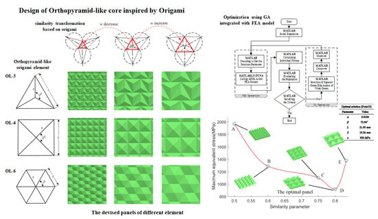
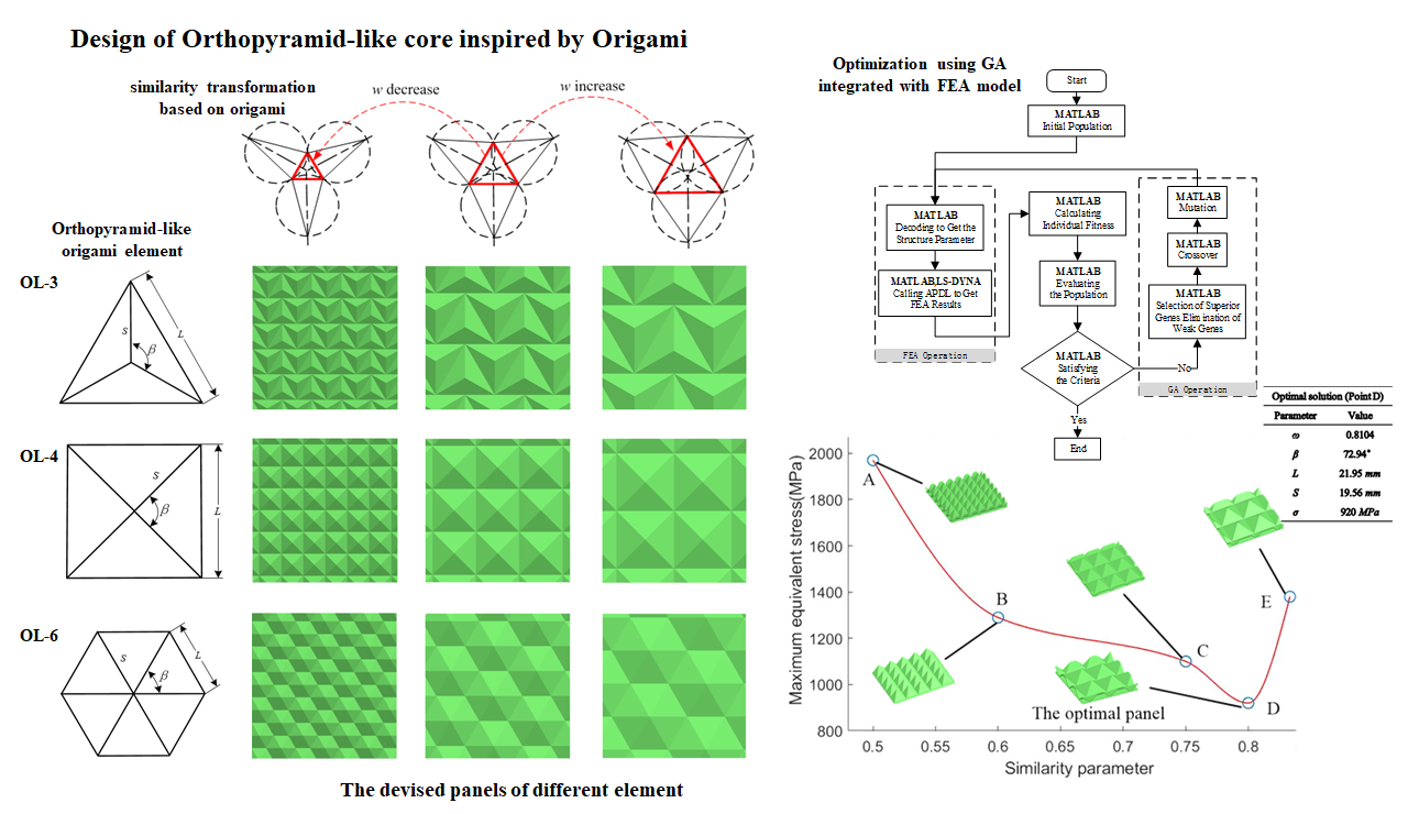
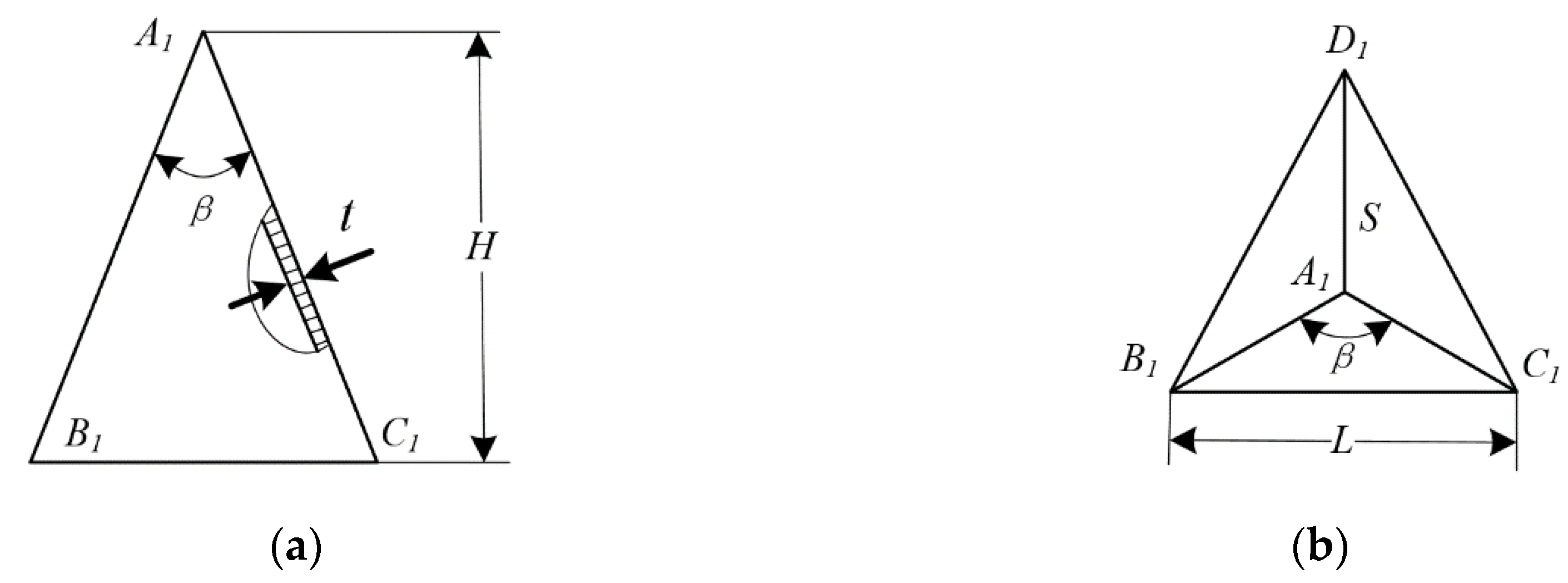
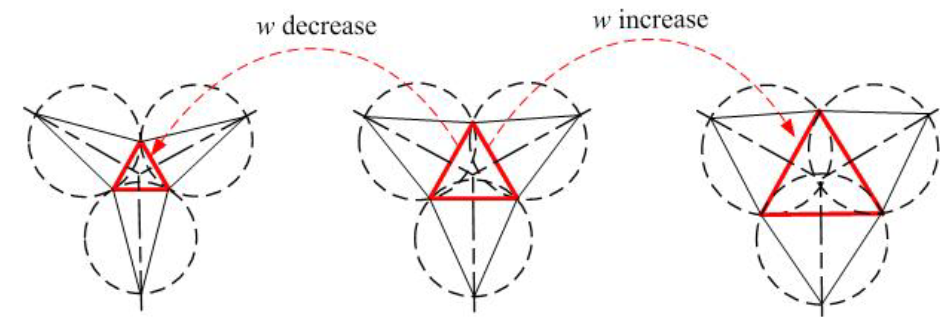
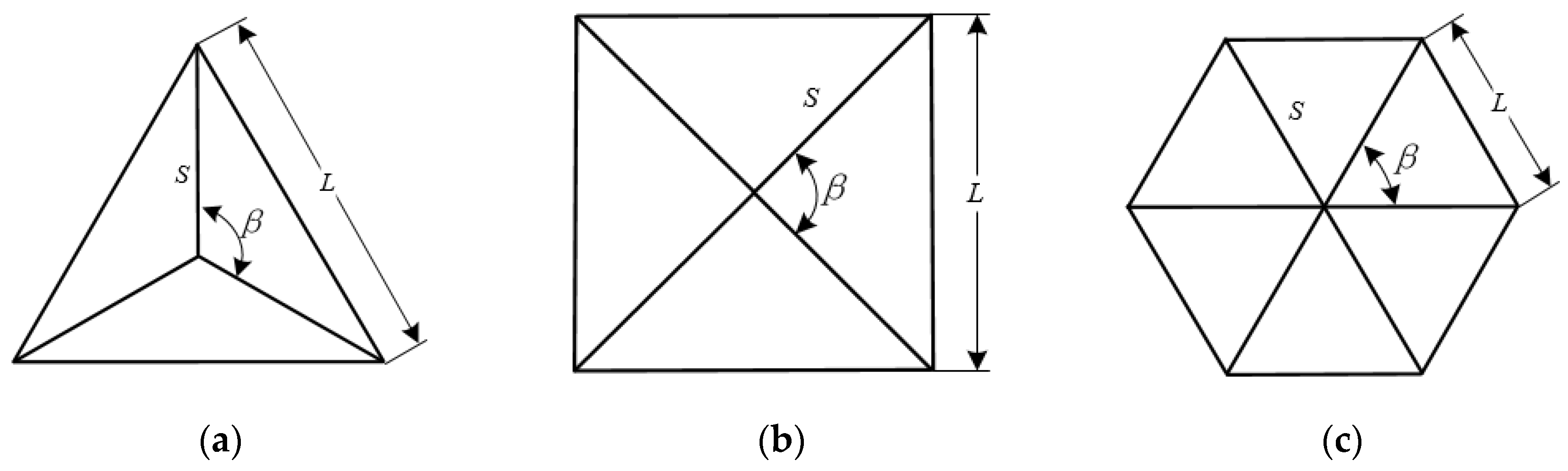
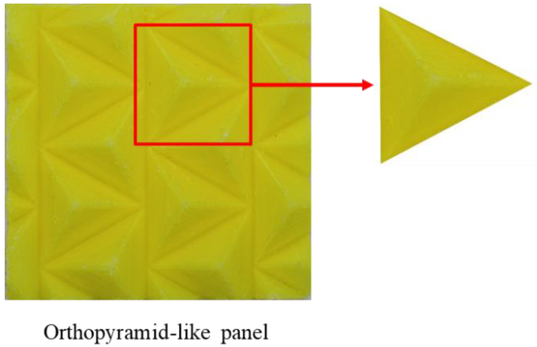
2.1. Orthopyramid-Like Origami Element Geometry

As one form of orthopyramid-like origami element, the triangular pyramid is shown in Figure 1. The origami element geometry can be parametrized by the height H, the tip angle β, the similarity parameter w, the edge number n, the bottom surface side length L, and the element thickness t. For a selected set of H and w, the parameters L and S can be calculated. According to our previous work [39,40], the different configurations could be obtained through the similarity transformation based on origami. Figure 2 illustrates the process of the similarity transformation based on origami. In this paper, we obtained different elements by changing the similarity parameter w and get the designed pattern through a close periodic arrangement.
This study only considered the tightly arranged tessellation patterns. The side length S and the height of origami element H are given by:
S = L 2 sin β 2 , β ( 0 , 360 n )
H = L 2 1 tan 2 β 2 1 tan 2 π n
For a fixed n, the different shape can be obtained by the similarity parameter w, which can be calculated by:
w = n β 360

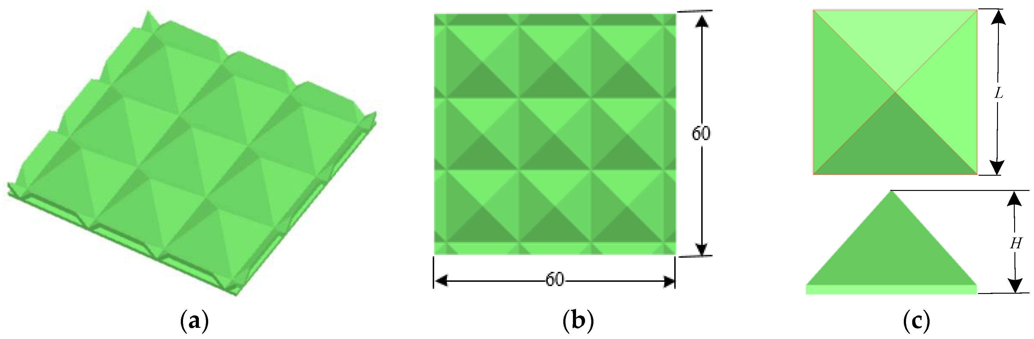
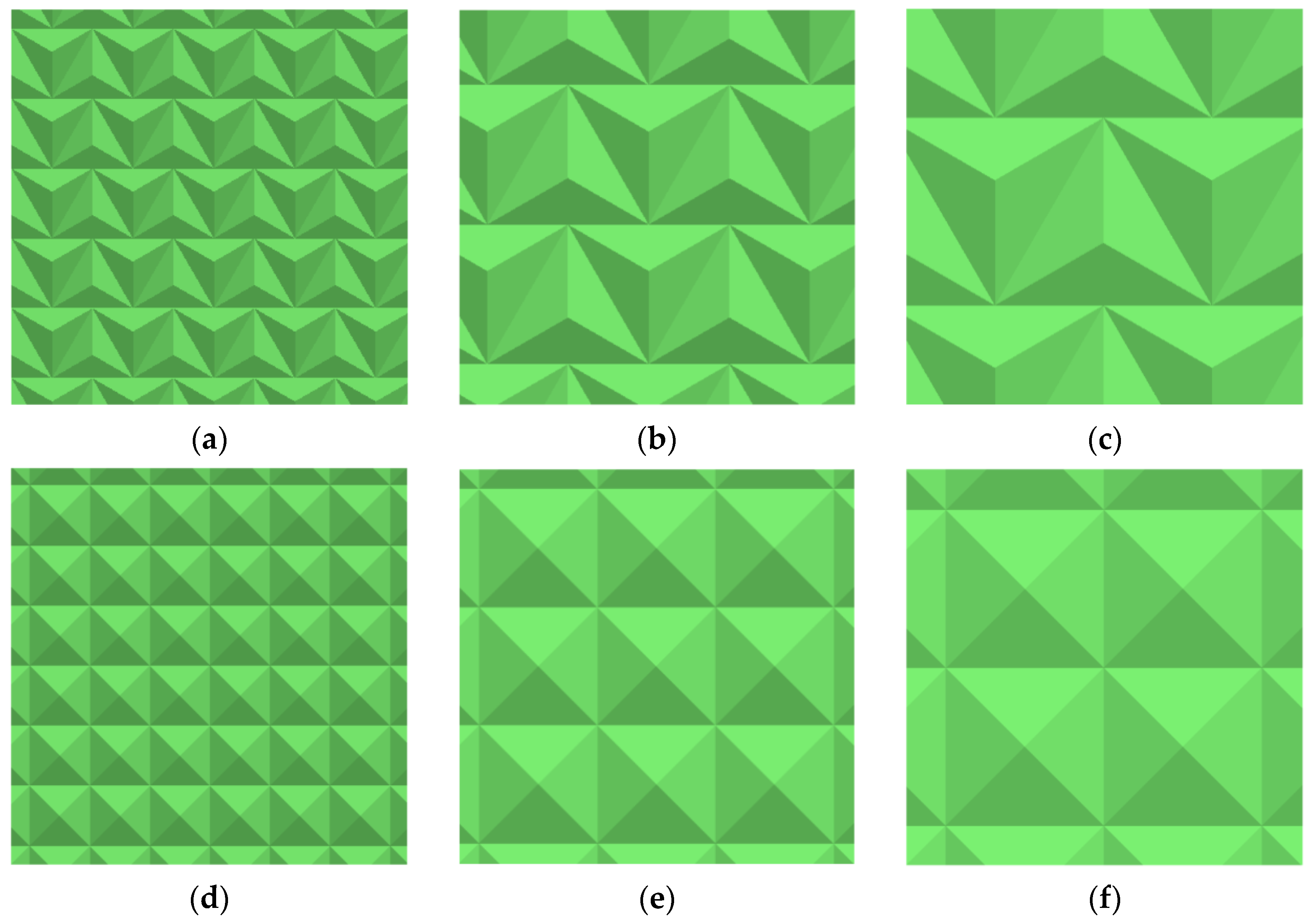
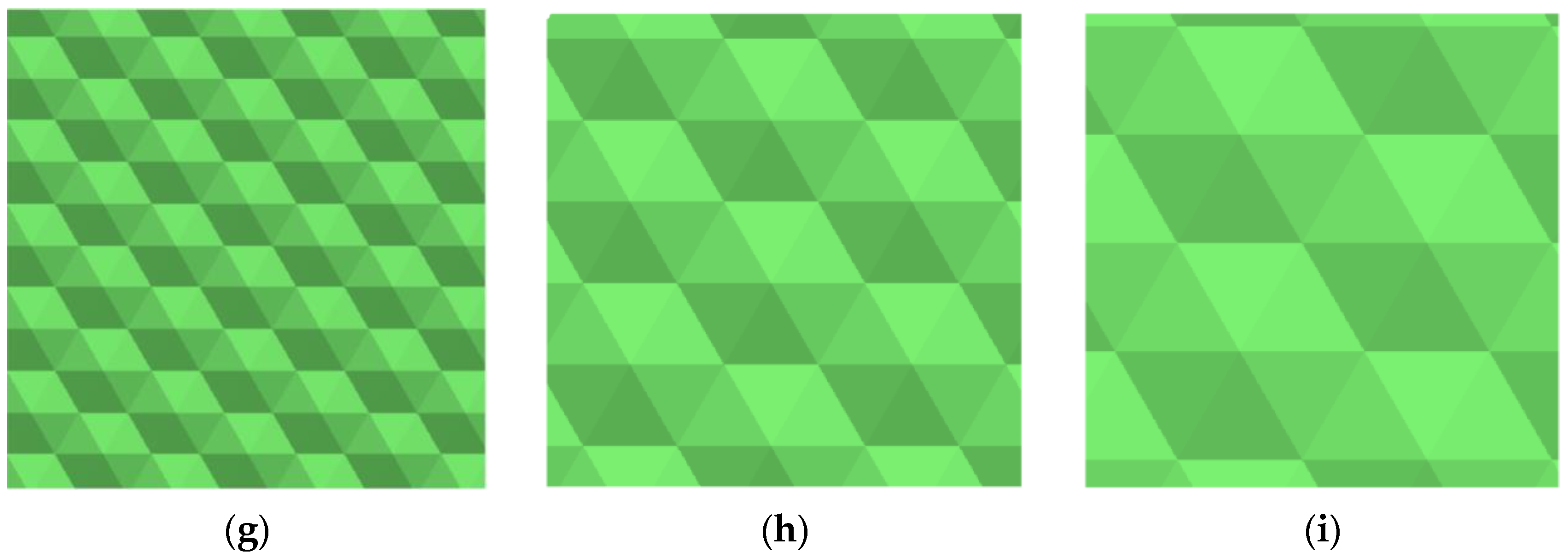
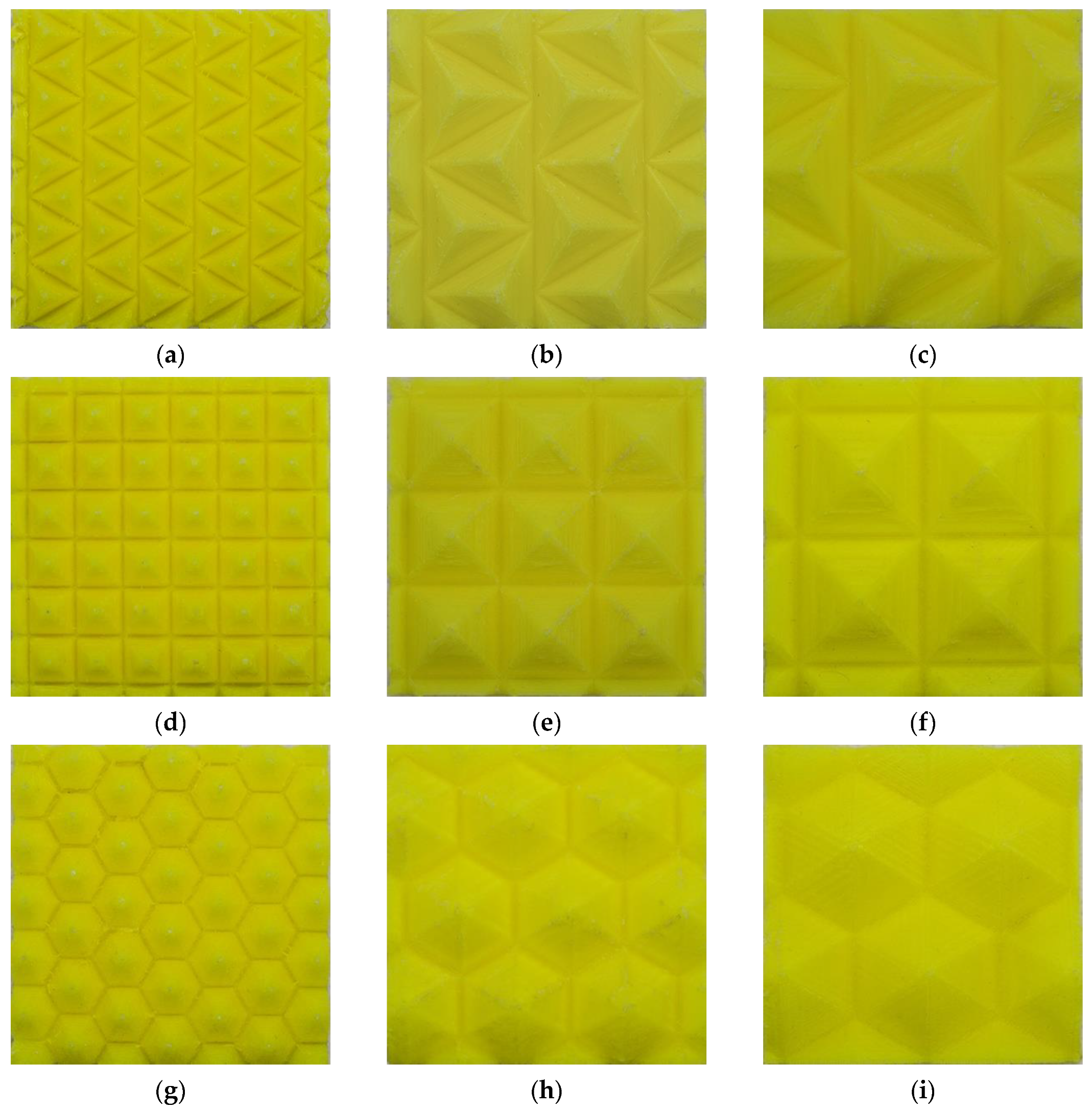
2.2. Orthopyramid-Like Origami Element and Panel Configurations

The height H of the element and the thickness t are set to be constant, and the structure of the orthopyramid-like origami element is parameterized by w and n. According to [45], regular triangles, regular quadrilateral, and regular hexagons are considered in this paper, in order to arrange the elements tightly in the plane. The overall size of the panel is 60 × 60 × 11 mm. The geometric detailed parameters of the origami element and panels are shown in Figure 3 and Figure 4. As shown in Figure 4, taking OL-4-3/4 as an example, OL is an abbreviation of orthopyrimid-like, 4 represents the n, and 3/4 stands for the w. The sizes of the elements are listed in Table 1, and the devised panels of different elements are shown in Figure 5.

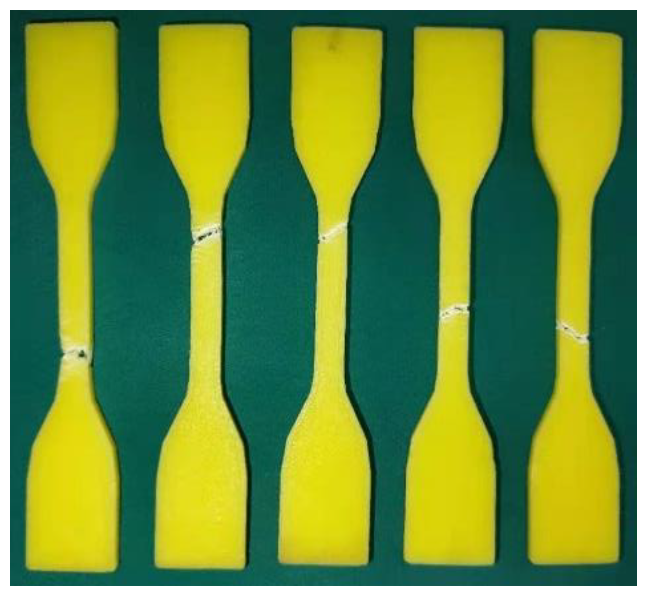
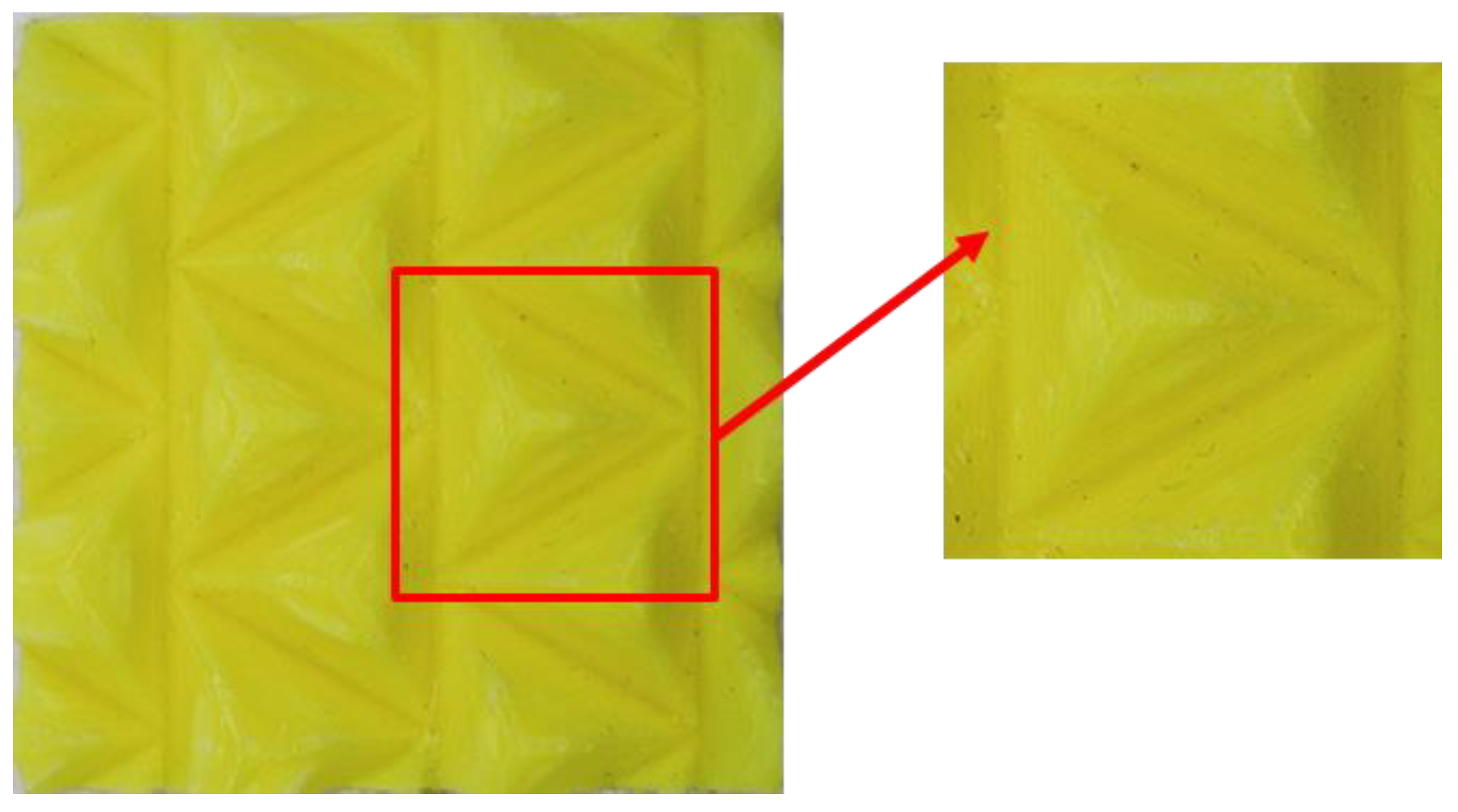
3. Fabrication of the Panel

State-of-the-art 3D printing, also known as fused deposition modeling, was employed to fabricate the panels. We used the parallel robot 3D printer provided by Zhejiang Province’s Key Laboratory of 3D Printing Process and Equipment with PLA diameter of 1.75 mm. Here are the fabrication conditions: The temperature of the extruder is 230 °C, the height of the layer is 0.2 mm, the speed of printing is 80 mm/s, the thickness of the printed structure is 1 mm, there is no structure chosen to reinforce the main origami structure. Figure 6 illustrates the 3D-printed orthopyramid-like origami-inspired core panel and the orthopyramid-like element. The models of the fabricated panels are shown in Figure 7.

4. Mechanical Testing Procedure

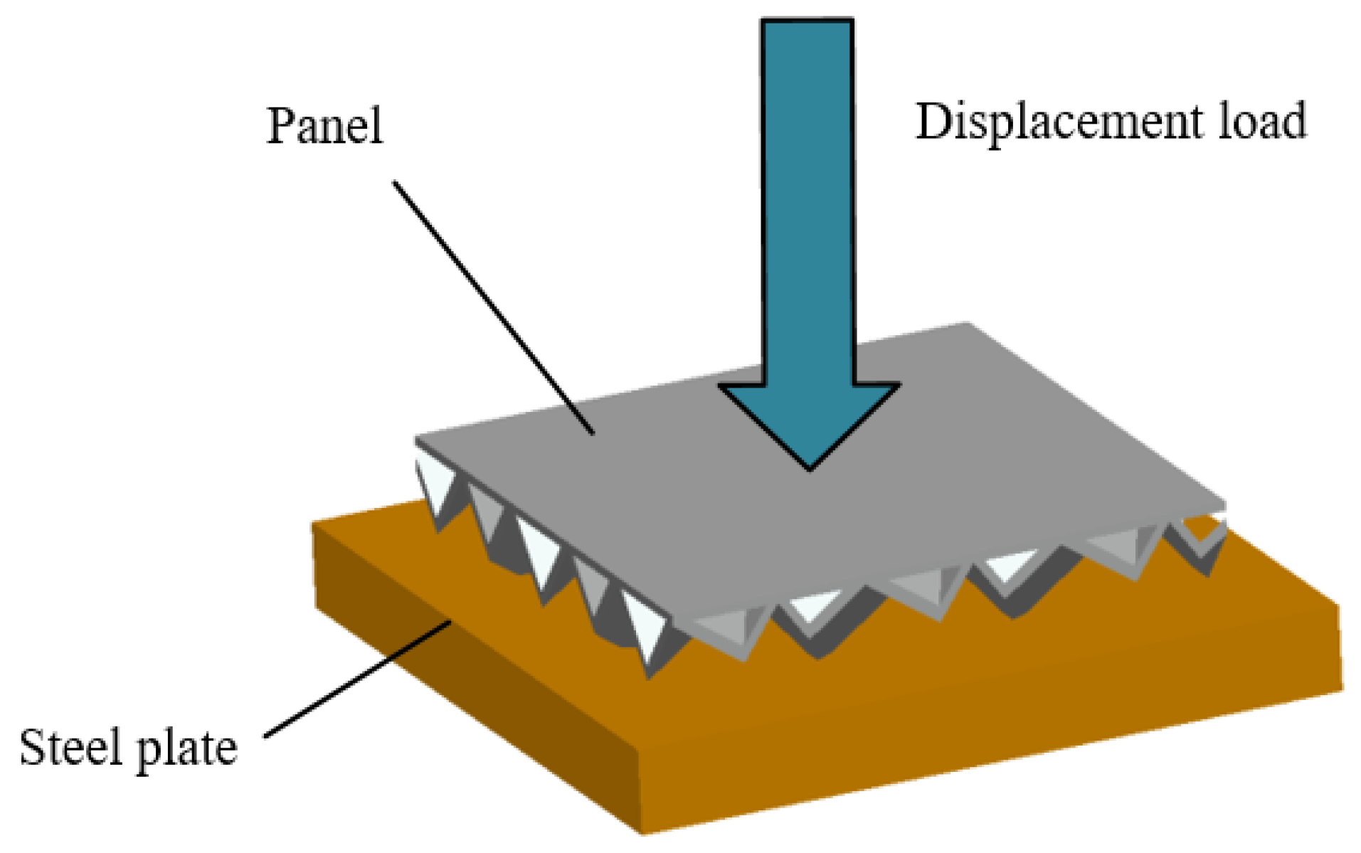
4.1. Compression Test
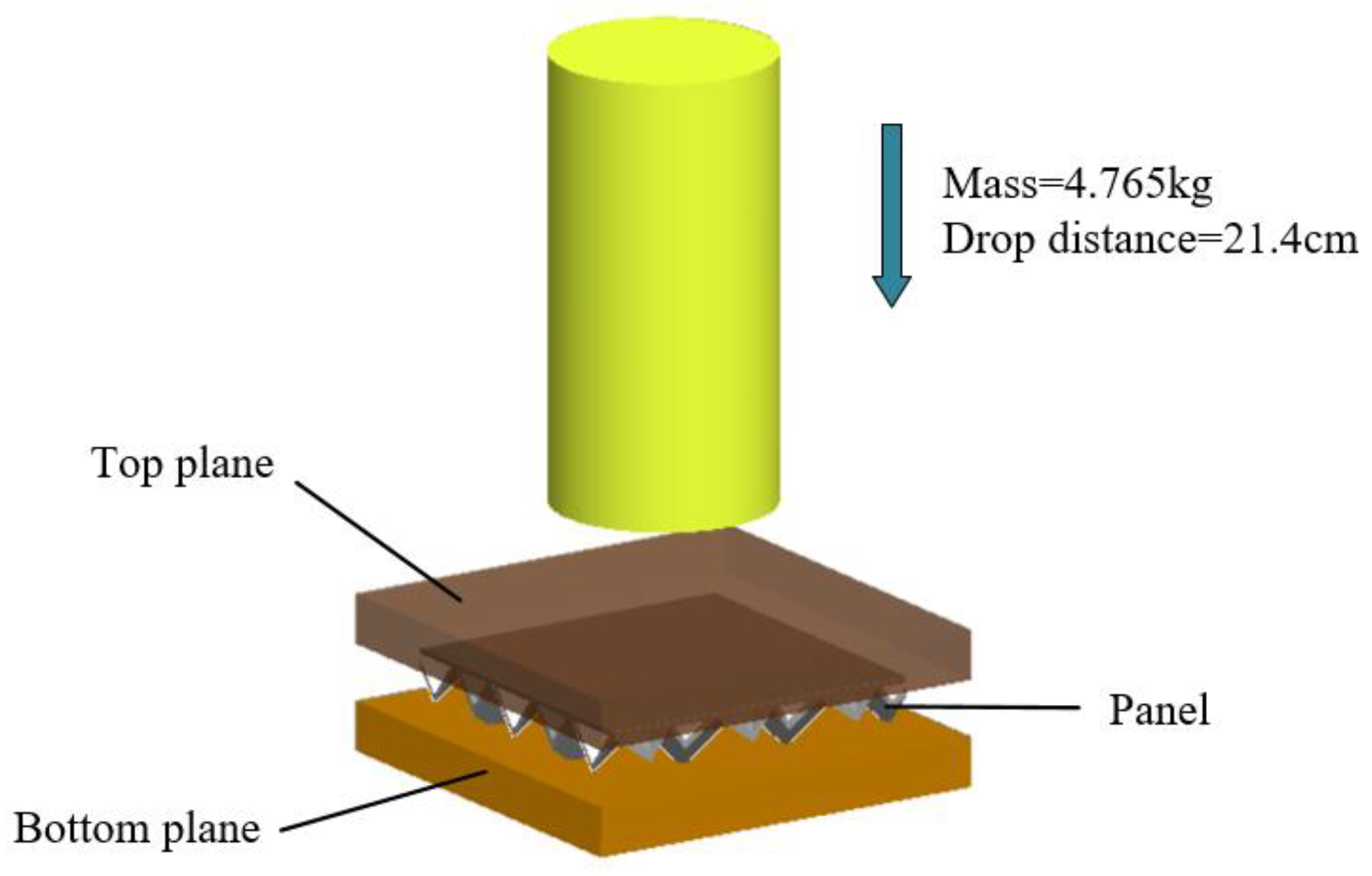
In order to estimate the fabricated panel performance under compressive loads, the compression test is conducted here. A compression-testing general machine WDW-100 (Bairoe, Shanghai, China) was employed to test the origami-inspired panel samples. For the load to be uniformly applied to the core panel structure, two thick steel plates were placed on both sides of the panel. A 1.5 mm/min stroke was used in the test, consistent with ASTM (American Society of Testing Materials) D1621/10 standards. Five specimens were tested for each origami structure.

4.2. Impact Test

Impact tests were conducted with each sample sandwiched and covered with a stainless steel plate on the tips of the panel. The tested panels were placed on the testing zone of the impact device. A CEAST9340 drop hammer impact test machine with a 16 mm diameter impact head was used to measure the load versus time. The impact test was conducted according to ASTM D7766/D7766M standards, with an impact velocity of 2.049 m/s and a testing drop weight of 4.765 kg. Five specimens were tested for each origami structure.

5. Finite Element Simulation

5.1. Material Properties

The fabricated part’s mechanical properties were tested by the Zwick/Roell Z020 tensile machine according to the ASTM D638, with part of the mechanical properties provided by the manufacturer. The mechanical properties are given as follows: Young’s modulus E = 2489 MPa, density ρ = 1240 kg/m3, Poisson’s ratio v = 0.3, initial yield stress σy = 15.56 MPa, ultimate stress σu = 38.20 MPa. The sample after tensile testing is shown in Figure 8.

5.2. Simulation of Compression Test

The ANSYS R18.2 software was used to carry the compression simulation. The panel was placed over a thick steel plate. The load is a displacement load applied as 4 mm on the top of the model. The steel plate is represented by solid elements. The six-degree freedom of the bottom of the steel plate is fixed. The panels are represented by shell elements. For the compromise of precision and efficiency, we chose the element size to be 2 mm. The compression model is shown in Figure 9.

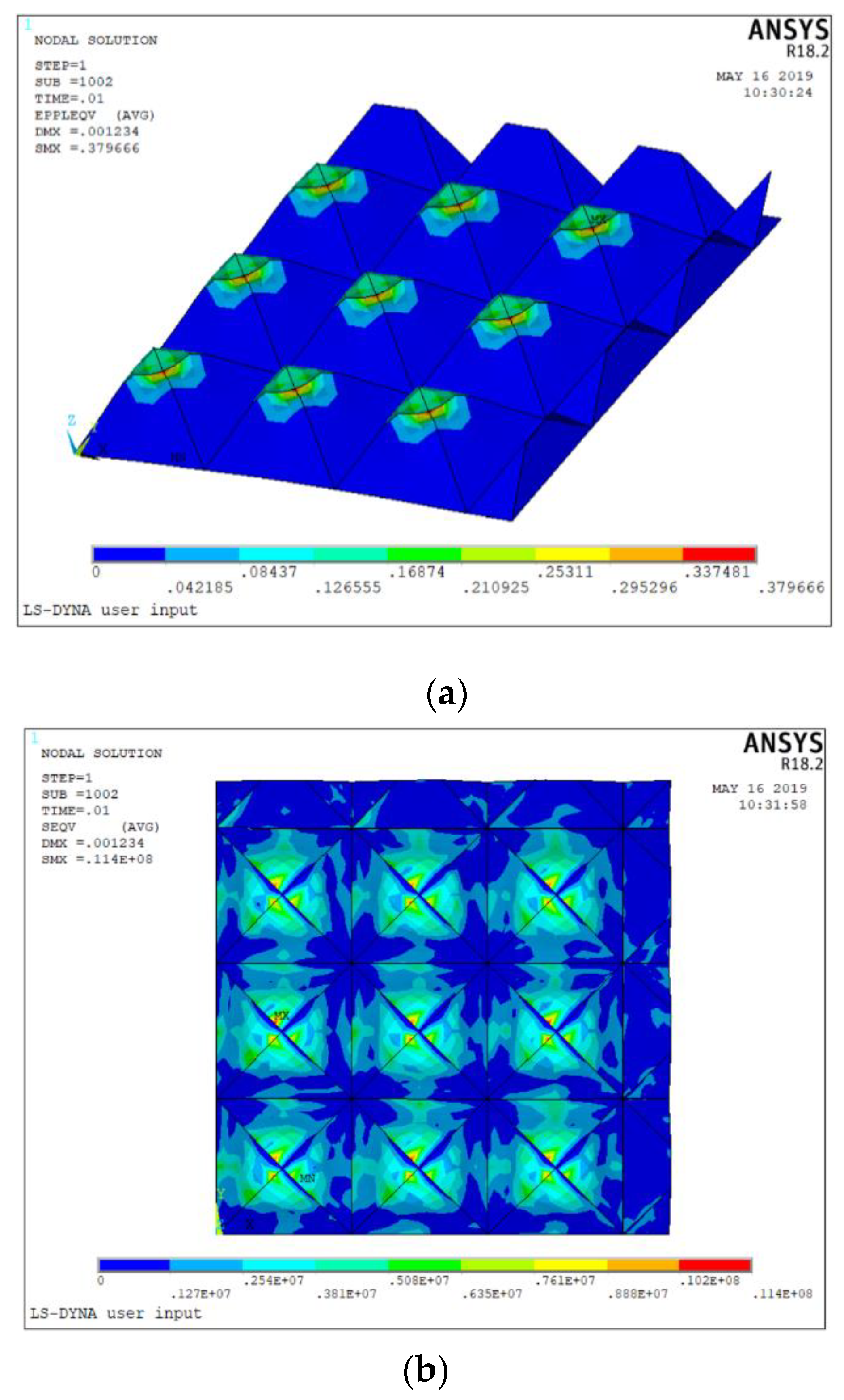
5.3. Simulation of Impact Test

The ANSYS explicit dynamics solver was employed to do the impact test simulation. The origami-inspired panel is represented by shell elements. The impactor, the sandwich top panel, and sandwich bottom panel are modeled as a rigid body. The impactor mass is 4.765 kg, the drop distance is 21.4 cm, and impact speed is 2.049 m/s. We used mapped meshing where possible; otherwise, we used free meshing to get the meshed geometry. The load between the impactor and the top panel were recorded. The impact model of the panel is shown in Figure 10.

6. Result and Discussion

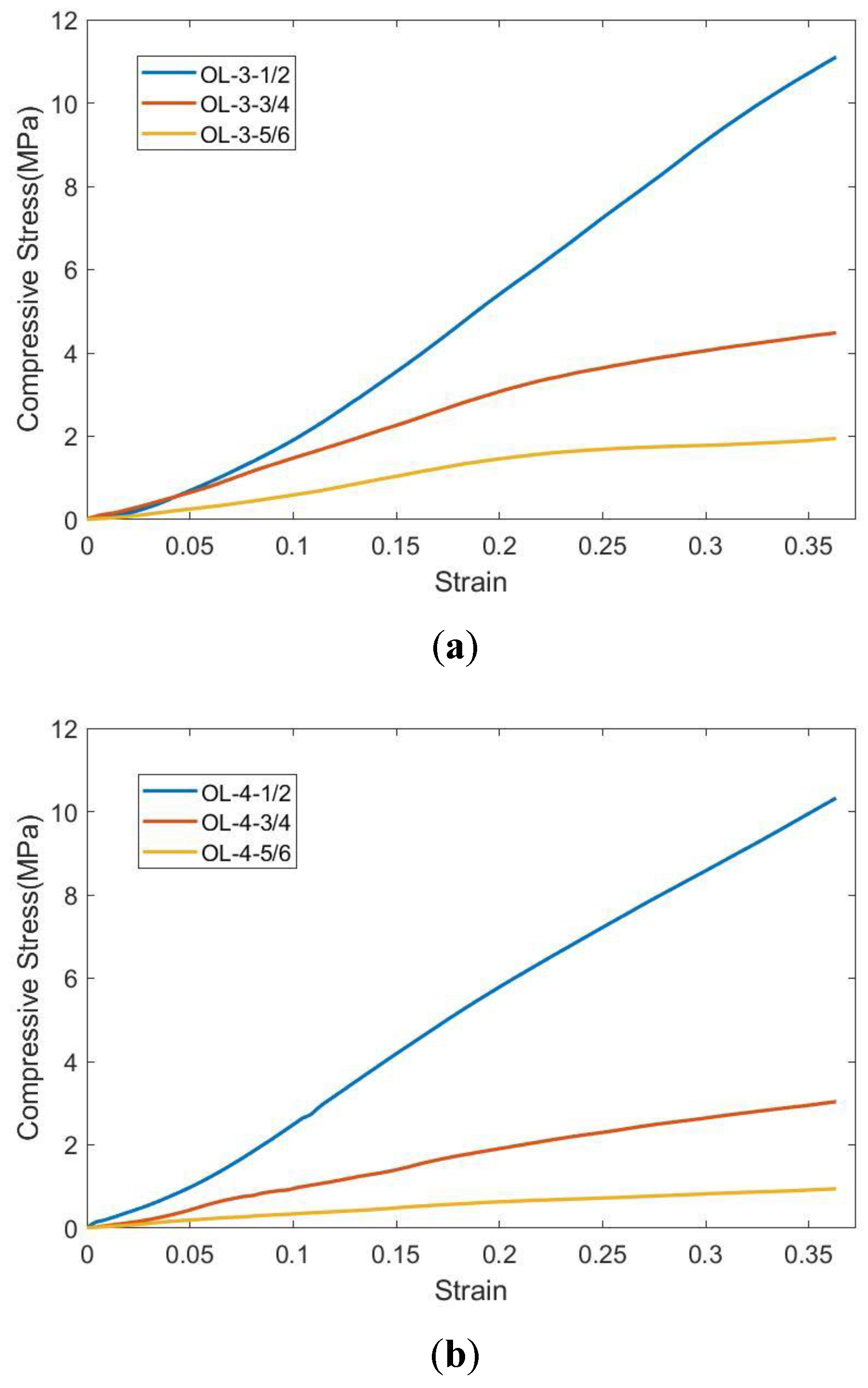
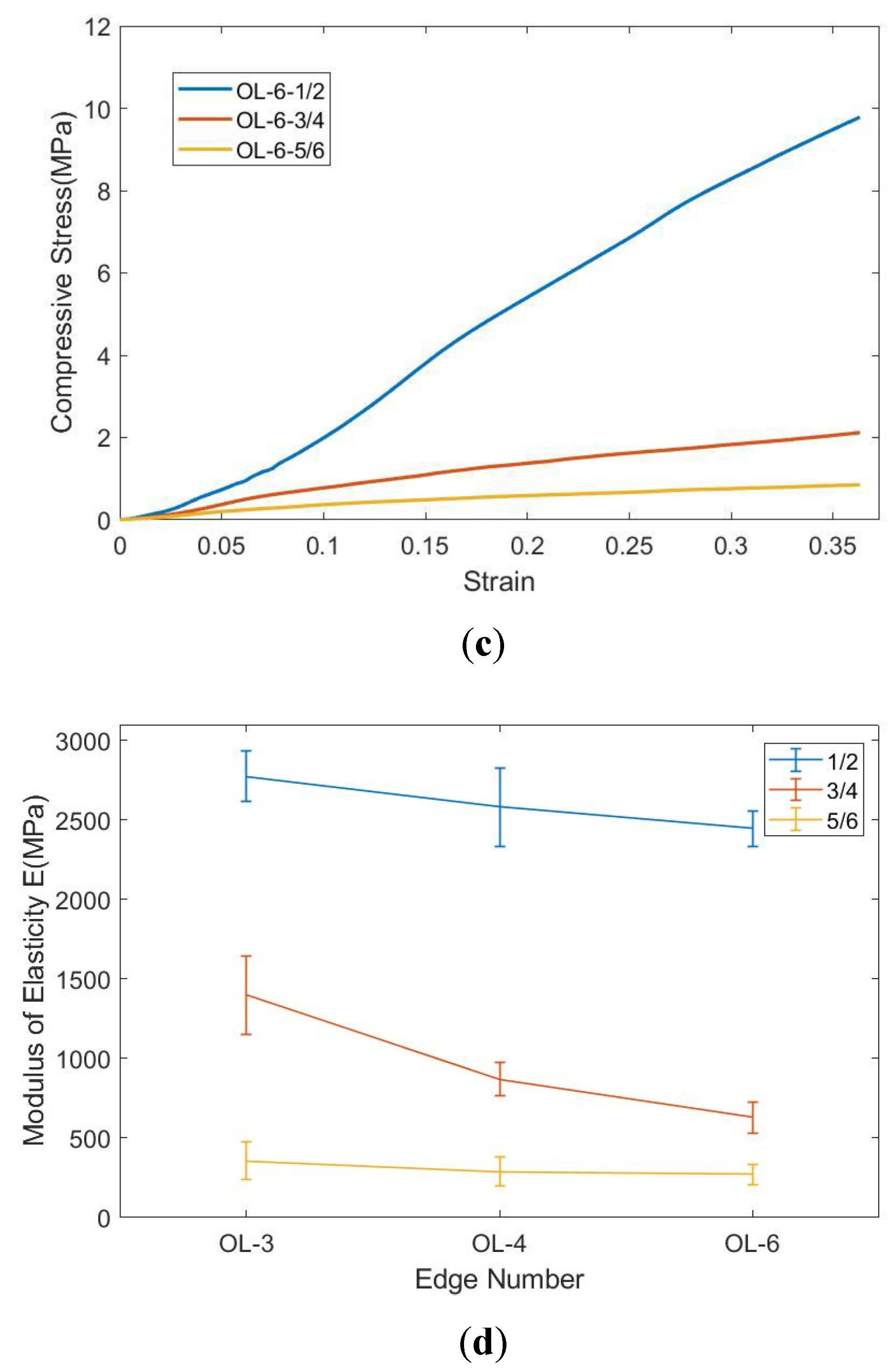
6.1. Result of Compression Test

The compression test of orthopyramid-like origami-inspired panels was conducted. Figure 11 shows the relationship of stress–strain of the tested panels in compression. The Young’s modulus of 9 panels are listed in Table 2. As shown in Figure 11a–c, the number of edges markedly affects the modulus value. It can be observed that Young’s modulus of panels decreases with the increase of the similarity parameter, as show in Figure 11d. Table 3 illustrates the comparison of the specific compressive modulus in regard to the similarity parameter and the number of edges, and it can be observed that the specific modulus of elasticity of 1/2 similarity parameter is almost the same with each of them.
Figure 12 shows the plastic deformation on the tips of the pyramid. It can be observed that the the tips of the element is the most deformed part of the panel. Due to the high-stress concentration on the tips of the bottom, the upper part of the plane does not show large plastic deformation. The OL-3 exhibits the highest modulus compared with four (OL-4) and six (OL-6) edges. The OL-3 models have higher Young’s modulus values compared with the others with the same similarity parameter. The explanation is that the OL-3 panels consist of more elements than the other two in the same area. This means that the intensity of the elements of OL-3 panels is larger.

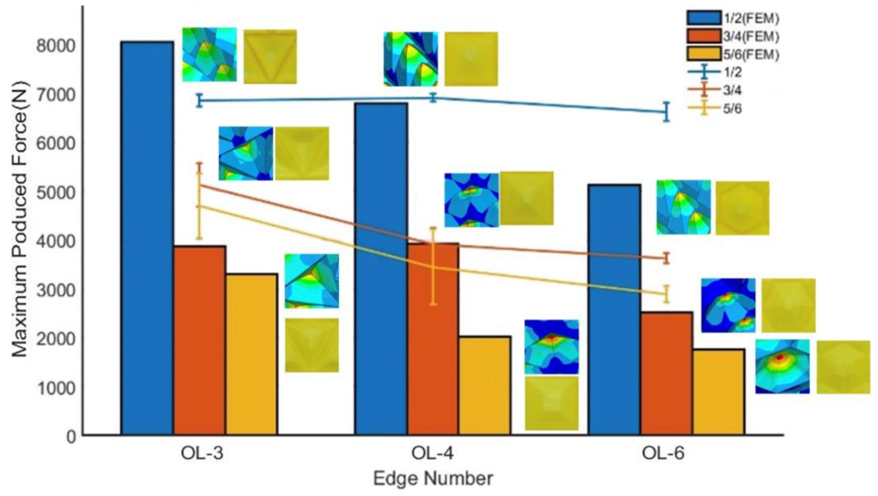
6.2. Result of Impact Test

The produced force changes versus time during the impact test was recorded. The force–time data were received by the sensor on the machine Figure 13 shows the force-time response received by the force sensor. As shown in Figure 13, a positive relevant relationship can be identified from the plot with similarity parameter and force fluctuation. However, the 1/2 similarity parameter configuration does not show apparent trends as the other two. Figure 14 compares the maximum force produced by the panels. For a fixed similarity parameter, the maximum force decreases with the increase of edge numbers. This means that the OL-3 panels produced the largest impact force and the OL-6 panels produced the smallest impact force. Among all the nine structures, OL-4-1/2 produced the maximum force of 6911.042 kN, and the minimum of maximum force produced is 2890.3 kN by OL-6-5/6. The values of the maximum forces produced are listed in Table 4. The panels produced lower impact force, however, with the expense of tips plastic fracture.

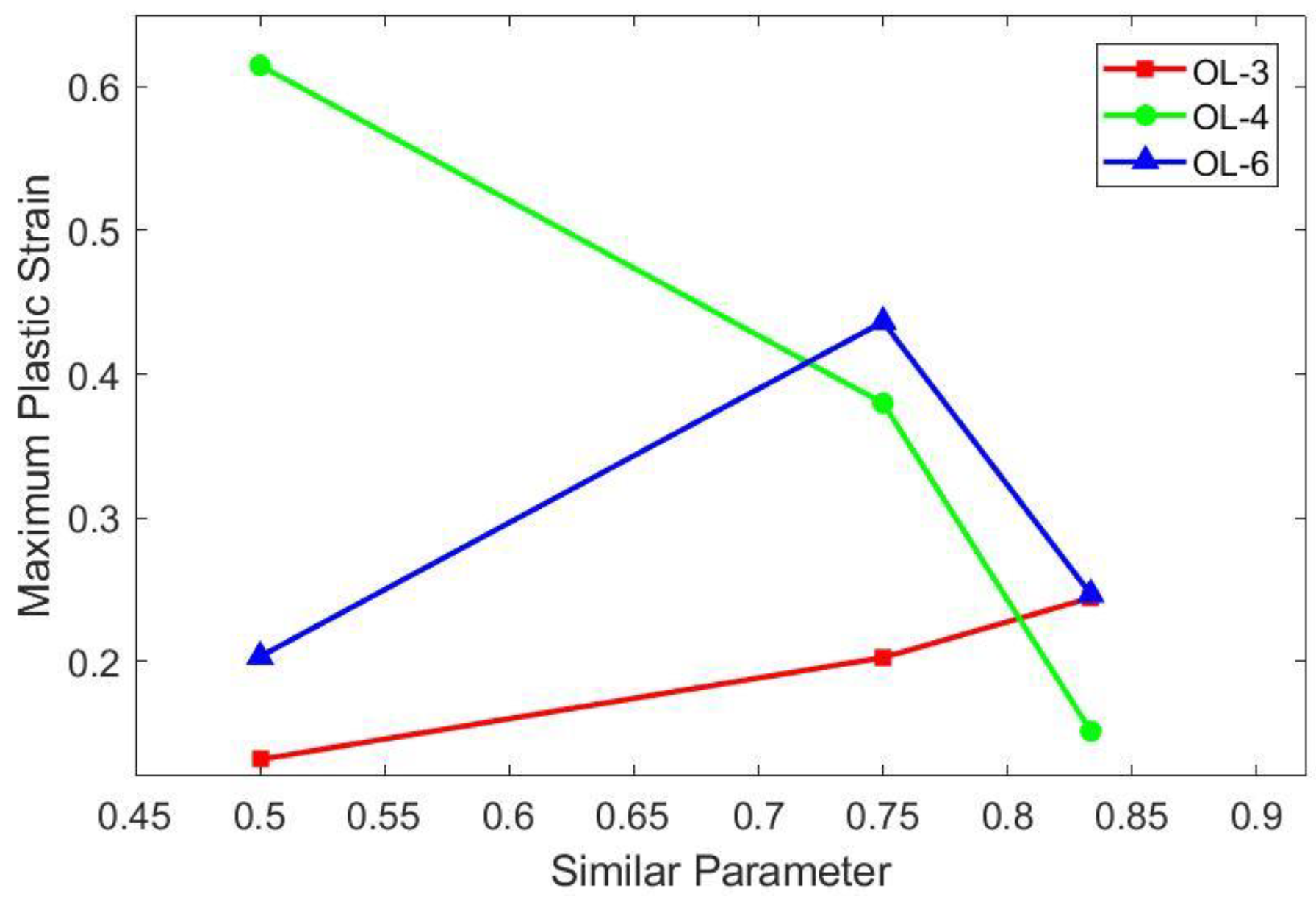
6.3. Simulation Result and Comparison

The ANSYS structural static solver was used to conduct the compression simulation of the orthopyramid-like core panels. The results revealed that the panels present large plastic deformation in compression, and the deformation presents a circular distribution on the tips. The distribution of stress on the element shows that the maximum stress occurs on the tip of the element. As illustrated in Figure 15, the simulation is accordant with the experimental results.
The total deformation of the OL-4-3/4 model is illustrated in Figure 16a. The maximum total deformation is 4 mm at the bottom. The directional deformation of the OL-4-3/4 model is shown in Figure 16b. The maximum mechanical strain and the maximum equivalent stress of the designed panels during compression simulation are compared in Table 5. It is apparent that the similarity parameter affects the stress and the deflection on the simulated panels. It was found that the maximum equivalent stresses all decrease with the increase of w for 3-edged and 6-edged elements. For the 4-edged element, the minimum stress appears in a similarity parameter of 3/4.
The impact property of the nine panels and their deformation were revealed using finite element simulations, too. Figure 17 illustrates the impact simulation of the OL-4-3/4 model. The ability of the structure to absorb energy and allocate force is explained by the collapse of the tips and stress concentration of the side edges. It indicates the effect of similarity parameter and the number of edges on the produced force. The table shows that the maximum produced force shows a decreasing tendency with the increase of edge numbers.
Figure 18 shows the comparsion of the deflection degree of the tips in impact simulation. It is consistent with test results that the most deformed place of the orthopyramid-like element is the tip. The deformation value depends on the similarity parameter and the number of edges. The element with small similarity parameters exhibited high deformation on the tip and a small deformation distribution along the side edges. The elements with bigger similarity parameters exhibit lower deformation near the tips and the deformation spread along the side edges. Figure 19 shows the simulated results of the maximum plastic strain of the panels. It can be observered that there is no apparent relationship between the maximum plastic strain and the similarity parameter.

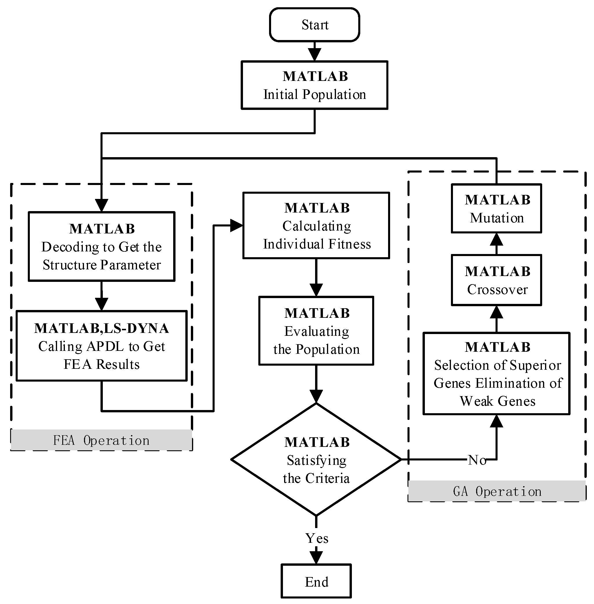
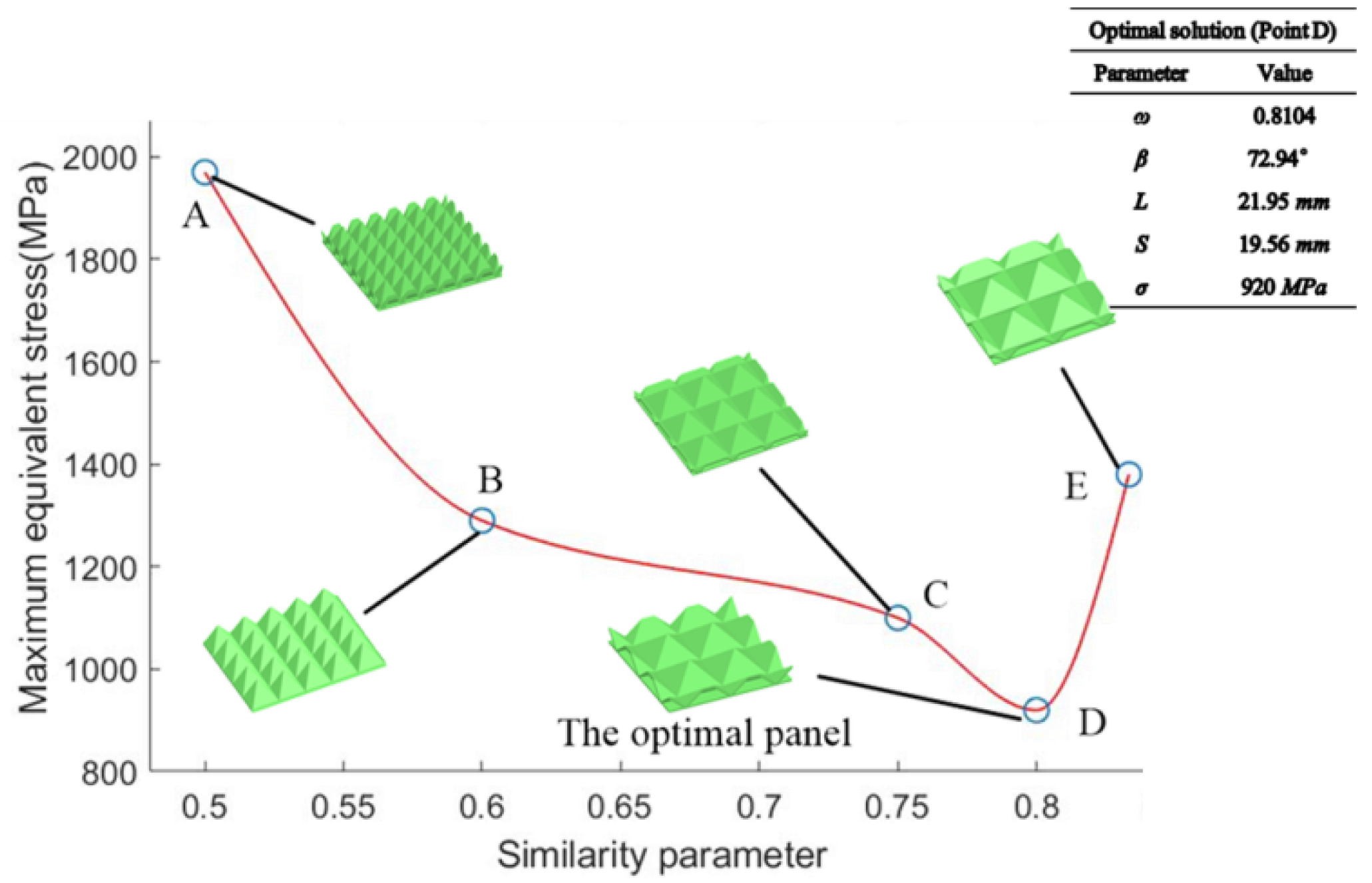
6.4. Optimize the Best Geometric Parameters

Section 6.3 finds that the influence of similarity parameter to 4-edged elements’ maximum equivalent stress, in compression simulations, are different than the other two. The stress value does not decrease with the increasing of the similarity parameter as shown in Table 5. The GA [46,47,48,49] integrated with the FEA model (using ANSYS software) was employed to find its optimal similarity parameters corresponding to the minimum equivalent stress. The individual fitness was increased with the decrease of the stress value. The basic flow chart of the algorithm is shown in Figure 20, which inherited the advantages of GA and the strong solution ability of FEA software.
The calculation steps are as follows:
Step 1: The running parameters of the Genetic Algorithm are set. The optimization variables were the population size; the cross probability; and the evolution termination parameter.
Step 2: Generate initial populations according to the selection strategy.
Step 3: The ANSYS parameter design language is used to calculate the maximum stress.
Step 4: The stress is used to calculate the individual fitness value and evaluate the population. If the iterative termination principle is satisfied, the iterative will stop. Otherwise, the process is switched to the next step.
Step 5: Operate the GA operation and get a new population. Go to Step 3.
In this specific implementation of the algorithm, our goal was to minimize the maximum stress. The optimization variable is the similarity parameter w, whose range is set to 1/2,5/6. Using the algorithm above, we find that the optimal similarity parameter w is 0.8104. The corresponding tip angle β is 72.94 °, the bottom surface side length L is 21.95 mm, and the side length S is 19.56 mm. The comparison of the non-optimal and optimal solutions is shown in Figure 21.

7. Conclusions and Prospect

Investigating the origami-inspired core panels could lead to the production of structures used in loads and energy damping applications. In the present work, 3D printing with PLA filaments was used to fabricate origami-inspired orthopyramid-like core panels. The compression and impact test was carried out on the fabricated panels. Finite element modeling was conducted using static structures for compression tests and explicit dynamics for an impact event. The results showed that the tips are the stress concentration zones. The deformation of the tips explains the load damping ability. The optimal similarity parameter for the 4-edged element was obtained via the GA algorithm. We found that the optimal similarity parameter w is 0.8104. The corresponding tip angle β was 72.94 °, the bottom surface side length L was 21.95 mm, and side length S was 19.56 mm.
However, there are also some limitations to our work. During the study of the load damping properties, several design hypotheses have been made, such as the panel material, panel thickness, and element thickness. We lack a generic mathematical formulation of the design problem. Further, more optimization objectives of the optimization algorithm should be included, not only the stress index.
In the future, different materials’ influences of the compression behavior should be studied. Multiobject optimization towards the geometry parameter in compression and impact simulation should be conducted, and it is important to investigate the tessellation pattern model toward a variety of edges.

Author Contributions

All authors have equally contributed to this article.

Funding

This work is supported by the National Key R&D Program of China (No. 2018YFB1701702), the National Natural Science Foundation of China (Nos. 51675477, 51775489), Zhejiang Provincial Natural Science Foundation of China (No. LZ18E050001). The authors would like to acknowledge the support of Zhejiang Province’s Key Laboratory of 3D Printing Process and Equipment.

Conflicts of Interest

The authors declare no conflict of interest.

References

  1. Zhou, X.; Wang, H.; You, Z. Mechanical properties of Miura-based folded cores under quasi-static loads. Thin Wall. Struct. 2014, 82, 296–310. [Google Scholar] [CrossRef]
  2. Florence, A.; Jaswin, M.A. Vibration and flexural characterization of hybrid honeycomb core sandwich panels filled with different energy absorbing materials. Mater. Res. Express. 2019, 6, 075326. [Google Scholar] [CrossRef]
  3. Birman, V.; Kardomateas, G.A. Review of current trends in research and applications of sandwich structures. Compos. Part B Eng. 2018, 142, 221–240. [Google Scholar] [CrossRef]
  4. Sebaey, T.A.; Mandi, E. Crushing behavior of a unit cell of CFRP lattice core for sandwich structures’ application. Thin Wall. Struct. 2017, 116, 91–95. [Google Scholar] [CrossRef]
  5. Wang, Y.P.; Gong, X.L.; Xuan, S.H. Study of low-velocity impact response of sandwich panels with shear-thickening gel cores. Smart Mater. Struct. 2018, 27, 065008. [Google Scholar] [CrossRef] [Green Version]
  6. Yu, B.; Han, B.; Su, P.; Ni, C.; Zhang, Q.; Lu, T. Graded square honeycomb as sandwich core for enhanced mechanical performance. Mater. Des. 2016, 89, 642–652. [Google Scholar] [CrossRef]
  7. Kumar, S.; Renji, K. Estimation of strains in composite honeycomb sandwich panels subjected to low frequency diffused acoustic field. J. Sound Vib. 2019, 449, 84–97. [Google Scholar] [CrossRef]
  8. Wang, Z.; Li, Z.; Xiong, W. Experimental investigation on bending behavior of honeycomb sandwich panel with ceramic tile face-sheet. Compos. Part B Eng. 2019, 164, 280–286. [Google Scholar] [CrossRef]
  9. Pan, G.; Zhang, P.; Liu, J. Experimental and numerical analyses on the dynamic response of aluminum foam core sandwich panels subjected to localized air blast loading. Mar. Struct. 2019, 65, 343–361. [Google Scholar]
  10. Yin, H.; Wen, G. Crashworthiness optimization design of honeycomb based on simplified basic folding element method. J. Mech. Eng. 2011, 47, 93–100. [Google Scholar] [CrossRef]
  11. Hao, J.; Wu, X.; Liu, W. Modeling and verification of sandwich beam with wooden skin and honey-comb core subjected to transverse loading. Sci. Silvae Sin. 2019, 50, 128–137. [Google Scholar]
  12. Seeliger, H.W. Aluminium foam sandwich (AFS) ready for market introduction. Adv. Eng. Mater. 2010, 6, 448–451. [Google Scholar] [CrossRef]
  13. Xin, F.; Lu, T. Analytical modeling of fluid loaded orthogonally rib-stiffened sandwich structures: Sound transmission. J. Mech. Phys. Sol. 2010, 58, 1374–1396. [Google Scholar] [CrossRef]
  14. Hýsek, Š.; Frydrych, M.; Herclík, M.; Louda, P.; Fridrichová, L.; Le Van, S.; Le Chi, H. Fire-Resistant Sandwich-Structured Composite Material Based on Alternative Materials and Its Physical and Mechanical Properties. Materials 2019, 12, 1432. [Google Scholar] [CrossRef] [PubMed]
  15. Hýsek, Š.; Frydrych, M.; Herclík, M.; Fridrichová, L.; Louda, P.; Knížek, R.; Le Van, S.; Le Chi, H. Permeable Water-Resistant Heat Insulation Panel Based on Recycled Materials and Its Physical and Mechanical Properties. Molecules 2019, 24, 3300. [Google Scholar] [CrossRef]
  16. Herrmann, A.S.; Zahlen, P.C.; Zuardy, I. Sandwich structures technology in commerical aviation: Present applications and future trends. J. Sandw. Struct. Mater. 2005, 7, 13–26. [Google Scholar]
  17. Sab, K.; Lebée, A. Transverse shear stiffness of a chevron folded core used in sandwich construction. Int. J. Sol. Struct. 2010, 47, 2620–2629. [Google Scholar] [Green Version]
  18. Elder, T.; Rozairo, D.; Croll, A.B. Origami inspired mechanics: Measuring modulus and force recovery with bent polymer films. Macromolecules 2019, 52, 690–699. [Google Scholar] [CrossRef]
  19. Peraza-Hernandez, E.A.; Hartl, D.J.; Malak, R.J., Jr.; Lagoudas, D.C. Origami-inspired active structures: A synthesis and review. Smart Mater. Struct. 2014, 23, 094001. [Google Scholar] [CrossRef]
  20. Turner, N.; Goodwine, B.; Sen, M. A review of origami applications in mechanical engineering. Proc Inst. Mech. Eng. C 2016, 230, 2345–2362. [Google Scholar] [CrossRef]
  21. Ma, J.; Hou, D.; Chen, Y. Quasi-static axial crushing of thin-walled tubes with a kite-shape rigid origami pattern: Numerical simulation. Thin Wall. Struct. 2016, 100, 38–47. [Google Scholar] [CrossRef]
  22. Schenk, M. Folded Shell Structures. Ph.D. Thesis, Clare College University of Cambridge, Cambridge, UK, 2011. [Google Scholar]
  23. Schenk, M.; Guest, S.D. Geometry of Miura-folded metamaterials. Proc. Natl. Acad. Sci. USA 2013, 110, 3276–3281. [Google Scholar] [CrossRef] [PubMed] [Green Version]
  24. Eidini, M.; Paulino, G.H. Unraveling metamaterial properties in zigzag-base folded sheets. Sci. Adv. 2015, 1, e1500224. [Google Scholar] [CrossRef] [PubMed] [Green Version]
  25. Hernandez, E.A.P.; Hartl, D.J.; Lagoudas, D.C. Design of origami structures with smooth folds. In Proceedings of the ASME 2016 Conference on Smart Materials, Adaptive Structures and Intelligent Systems, Stove, VT, USA, 28–30 September 2016. [Google Scholar]
  26. Tachi, T. Designing freeform origami tessellations by generalizing Resch’s patterns. J. Mech. Design. 2013, 135, 111006. [Google Scholar] [CrossRef]
  27. Feng, H.; Ma, J.; Chen, Y.; You, Z. Twist of tubular mechanical metamaterials based on waterbomb origami. Sci. Rep. 2018, 8, 9522. [Google Scholar] [CrossRef] [PubMed]
  28. Cai, J.; Deng, X.; Xu, Y.; Feng, J. Motion analysis of a foldable barrel vault based on regular and irregular yoshimura origami. J. Mech. Robot. 2016, 8, 021017. [Google Scholar] [CrossRef]
  29. Zakirov, I.I. Study of creasing parameters at shaping of folded cores in sandwich panels. Russ. Aeronaut. 2013, 56, 191–193. [Google Scholar] [CrossRef]
  30. Zakirov, I.M.; Alekseev, K.A.; Kayumov, R.A.; Gainutdinov, I.R. Some possible techniques for improving the strength characteristics of folded cores from sheet composite materials. Russ. Aeronaut. 2009, 52, 347–350. [Google Scholar] [CrossRef]
  31. Kayumov, R.A.; Zakirov, I.M.; Alekseev, K.P.; Alekseev, K.A.; Zinnurov, R.A. Determination of load-carrying capacity in panels with chevron-type cores. Russ. Aeronaut. 2007, 50, 357–361. [Google Scholar] [CrossRef]
  32. Wang, F.; Guo, X.; Xu, J.; Zhang, Y.; Chen, C.Q. Patterning curved three-dimensional structures with programmable kirigami designs. Int. J. Appl. Mech. 2017, 84, 061007. [Google Scholar] [CrossRef]
  33. Nasser, H.; Lebee, A.; Monasse, L. Curvature, metric and parametrization of origami tessellations: Theory and application to the eggbox pattern. Proc. R. Soc. A Math. Phys. Eng. Sci. 2017, 473, 20160705. [Google Scholar] [CrossRef] [PubMed]
  34. Zhang, P.; Li, X.; Wang, Z.; Zhao, L.; Yan, X. Dynamic blast loading response of sandwich beam with origami-inspired core. Res. Phys. 2018, 10, 946–955. [Google Scholar] [CrossRef]
  35. Kshad, M.A.E.; Naguib, H.E. Development and modeling of multi-phase polymeric origami inspired architecture by using pre-molded geometrical features. Smart Mater. Struct. 2017, 26, 025012. [Google Scholar] [CrossRef]
  36. Kshad, M.A.E.; Popinigis, C.; Naguib, H.E. 3D printing of Ron-Resch-like origami cores for compression and impact load damping. Smart Mater. Struct. 2019, 28, 015027. [Google Scholar] [CrossRef]
  37. Saito, K.; Nojima, T.; Hagiwara, I. Relation between geometrical patterns and mechanical properties in newly developed light-weight core panels. Trans. JSME. A 2008, 74, 1580–1586. [Google Scholar] [CrossRef]
  38. Li, D.; Dai, N.; Tang, Y.; Dong, G.; Zhao, Y. Design and optimization of graded cellular structures with triply periodic level surface-based topological shapes. J. Mech. Des. 2019, 141, 071402. [Google Scholar] [CrossRef]
  39. Liu, J.T.; Feng, Y.X.; Zheng, H.; Tan, J.R. Innovative design of regular unit-cell and energy-absorbing features under impact of polyhedron sandwich structure. Chin. J. Mech. 2017, 53, 147–156. [Google Scholar] [CrossRef]
  40. Qiu, H.; Gao, Y.C.; Feng, Y.X.; Zheng, H.; Tan, J.R. The evolutionary mechanism of unit cell: Parameterizations of polyhedron sandwich structure based on rigid origami. In Proceedings of the 18th International Conference on Geometry and Graphics, Milan, Italy, 3–7 August 2018; pp. 701–710. [Google Scholar]
  41. Yap, Y.L.; Yeong, W.Y. Shape recovery effect of 3D printed polymeric honeycomb. Virt. Phys. Prototyp. 2015, 10, 91–99. [Google Scholar] [CrossRef]
  42. Li, S.; Fang, H.; Sadeghi, S.; Bhovad, P.; Wang, K.W. Architected origami materials: How folding creates sophisticated mechanical properties. Adv. Mater. 2019, 31, 1805282. [Google Scholar] [CrossRef]
  43. Zadpoor, A.A. Mechanical meta-materials. Mater. Horiz. 2016, 3, 371–381. [Google Scholar] [CrossRef] [Green Version]
  44. Zeng, S.; Gao, Y.; Feng, Y.; Zheng, H.; Qiu, H.; Tan, J. Programming the deformation of a temperature-driven bilayer structure in 4D printing. Smart Mater. Struct. 2019, 28, 105031. [Google Scholar] [CrossRef]
  45. Evans, A.G.; Hutchinson, J.W.; Fleck, N.A.; Ashby, M.F.; Wadley, H.N.G. The topological design of multifunctional cellular metals. Prog. Mater. Sci. 2001, 46, 309–327. [Google Scholar] [CrossRef]
  46. Lahoz-Beltra, R. Quantum genetic algorithms for computer scientists. Computers 2016, 5, 24. [Google Scholar] [CrossRef]
  47. Gao, Y.; Feng, Y.; Wang, Q.; Zheng, H.; Tan, J. A multi-objective decision making approach for dealing with uncertainty in EOL product recovery. J. Clean. Prod. 2018, 204, 712–725. [Google Scholar] [CrossRef]
  48. Gao, Y.; Feng, Y.; Zhang, Z.; Tan, J. An optimal dynamic interval preventive maintenance scheduling for series systems. Reliab. Eng. Syst. Saf. 2015, 142, 19–30. [Google Scholar] [CrossRef]
  49. Feng, Y.; Gao, Y.; Tian, G.; Li, Z.; Hu, H.; Zheng, H. Flexible Process Planning and End-of-Life Decision-Making for Product Recovery Optimization Based on Hybrid Disassembly. IEEE Trans. Autom. Sci. Eng. 2018, 99, 1–16. [Google Scholar] [CrossRef]
Figure 1. Origami element of triangular pyramid. (a) Front view; (b) top view.
Applsci 09 04619 g001
Figure 2. The process of the similarity transformation based on origami.
Applsci 09 04619 g002
Figure 3. The designed orthopyramid-like origami element. (a) OL-3; (b) OL-4; (c) OL-6.
Applsci 09 04619 g003
Figure 4. OL-4-3/4 model as an example. (a) Three-dimensional picture; (b) the top view; (c) the detailed dimensions.
Applsci 09 04619 g004
Figure 5. The devised panels of different elements. (a) OL-3-1/2; (b) OL-3-3/4; (c) OL-3-5/6; (d) OL-4-1/2; (e) OL-4-3/4; (f) OL-4-5/6; (g) OL-6-1/2; (h) OL-6-3/4; (i) OL-6-5/6.
Applsci 09 04619 g005aApplsci 09 04619 g005b
Figure 6. 3D-printed panel and element.
Applsci 09 04619 g006
Figure 7. 3D-printed core panels. (a) OL-3-1/2; (b) OL-3-3/4; (c) OL-3-5/6; (d) OL-4-1/2; (e) OL-4-3/4; (f) OL-4-5/6; (g) OL-6-1/2; (h) OL-6-3/4; (i) OL-6-5/6.
Applsci 09 04619 g007
Figure 8. Samples after tensile testing.
Applsci 09 04619 g008
Figure 9. Compression model of the panel (OL-4-3/4).
Applsci 09 04619 g009
Figure 10. Impact model of the panel (OL-3-3/4).
Applsci 09 04619 g010
Figure 11. Comparision of stress–strain and Young’s modulus. (a) Stress–strain curves of OL-3; (b) stress–strain curves of OL-4; (c) stress–strain curves of OL-6; (d) Ccmparision of Young’s modulus.
Applsci 09 04619 g011aApplsci 09 04619 g011b
Figure 12. The panel plastic deformation.
Applsci 09 04619 g012
Figure 13. Produced force versus time in impact.
Applsci 09 04619 g013
Figure 14. The experiment maximum impact forces.
Applsci 09 04619 g014
Figure 15. The compressive deformation of the OL-4-3/4 panel compared with the tested sample.
Applsci 09 04619 g015
Figure 16. The compressive deformation of OL-4-3/4 panel. (a) The whole compressive deformation; (b) the z-directional compressive deformation.
Applsci 09 04619 g016
Figure 17. The impact simulation of OL-4-3/4 model. (a) The total deformation plastic strain in impact event; (b) The equivalent von-Mises Stress distribution on the panel.
Applsci 09 04619 g017
Figure 18. Comparison of the maximum produced force.
Applsci 09 04619 g018
Figure 19. The FEM results of the maximum plastic strain of the panels.
Applsci 09 04619 g019
Figure 20. Basic flow chart of the algorithm.
Applsci 09 04619 g020
Figure 21. Comparison with the optimized panel.
Applsci 09 04619 g021
Table 1. The sizes of the designed orthopyramid-like origami elements.
SampleH (mm)L (mm)S (mm)w
OL-3-1/21012.2512.251/2
OL-3-3/41024.5017.323/4
OL-3-5/61032.8521.445/6
OL-4-1/2109.1011.901/2
OL-4-3/41017.9616.163/4
OL-4-5/61023.9319.655/6
OL-6-1/2106.0511.691/2
OL-6-3/41011.8915.543/4
OL-6-5/61015.8218.725/6
Table 2. Young’s modulus.
Edge NumberSimilarity ParameterYoung’s Modulus (MPa)
OL-31/22442.9 ± 160.8
3/41399.2 ± 247.3
5/6357.6 ± 117.3
OL-41/22632.6 ± 245.2
3/4870.8 ± 105.9
5/6290.3 ± 93.8
OL-61/22456.5 ± 110.3
3/4629.6 ± 97.8
5/6271.7 ± 63.0
Table 3. Specific modulus of elasticity.
Edge NumberSimilarity ParameterSpecific Modulus of Elasticity (MPa/kg)
OL-31/2195,800 ± 11,340
3/4128,300 ± 22,680
5/666,150 ± 11,660
OL-41/2203,500 ± 19,330
3/4869,100 ± 10,570
5/630,800± 9955
OL-61/2199,700 ± 8999
3/464,230 ± 9979
5/629,360 ± 6811
Table 4. The maximum impact forces produced by the panels.
Edge NumberSimilarity ParameterThe Maximum Impact Forces (N)
OL-31/26851.8 ± 122.8
3/45128.6 ± 442.0
5/64699.6 ± 662.6
OL-41/26911.0 ± 80.4
3/43906.4 ± 339.4
5/63448.2 ± 767.2
OL-61/26620.8 ± 191.9
3/43627.0 ± 104.4
5/62890.3 ± 166.2
Table 5. Comparision of maximum mechanical strain and maximum equivalent stress.
Edge NumberSimilarity ParameterMaximum Equivalent StrainMaximum Equivalent Stress (MPa)
OL-31/20.6852330
3/40.5501650
5/60.453913
OL-41/24461970
3/40.5441100
5/60.6761380
OL-61/20.6022890
3/40.6921490
5/60.4221000

