1. Introduction
Portable electronic devices, such as tablet computers and smartphones, are now immensely popular. It is estimated that the number of tablet users around the world was 591 million in 2015 while the forecast for 2018 was 1.43 billion, nearly a threefold increase [
1]. Tablet computers and smartphones are devices with 5- to 14-inch displays and touch-screen interfaces that run a lightweight operating system, such as Apple iOS, Android OS, or Windows [
2]. Nowadays, these devices can execute sophisticated applications, including video editing, 3D gaming, and on-demand access to the internet. These applications require high-performance components capable of processing more data, more rapidly. Particularly, the requirements for the central processing unit (CPU) and the graphic processing unit (GPU), which are integrated into the system on a chip (SoC), have increased substantially [
3]. While the performance capability is increasing, the thickness of the tablet computers and smartphones is decreasing. The newest tablet generation of Apple (iPad Air 2) and Samsung (Galaxy Tab S2) have an overall thickness of only 6 and 5.7 mm, respectively [
4]. Due to compact construction, these devices do not have any active cooling parts (heat sinks and fans), which are found in more spacious desktop personal computer (PC) or notebooks. Therefore, thermal management and, in particular, the cooling capability have become a serious concern for current tablet computer and smartphone manufacturers [
5].
A modern SoC contains over a billion transistors. Failure mechanisms, such as dielectric breakdown, are exponentially dependent on temperature [
6]. Moreover, the leakage power consumption of these devices, which is the result of an unwanted subthreshold current in transistors when turned off, also exponentially increases with temperature [
7]. The probability of thermal runaway processes in Li-ion batteries is increased under abuse conditions, such as overheating [
8]. This all points to the need for improved thermal management in handheld electronic devices to avoid overheating of internal electronic components.
The temperature increase of the internal electronic components is a serious concern, but the resulting temperature increase of the outer surface is also problematic. Portable electronic devices are in direct contact with the consumer’s hands. According to the investigations performed by Berhe [
9], cover temperatures above 43 to 45 °C lead to users’ discomfort when touching the device. Accordingly, the thermal management system of tablet computers and smartphones needs to address both a comfortable surface touch temperature and maximum temperature limitations of critical power-consuming electronic components.
An interesting approach that could lead to a reduction of peak temperatures and therefore increased time of operation of electronic components is based on phase change materials (PCMs) integration into the design of tablets [
10,
11,
12]. Typically, portable electronic devices operate in transient cycles, meaning that heat is produced during short periods of demanding use, followed by longer periods of idling or less demanding use. PCMs will absorb heat dissipated from the electronics through a solid–liquid phase change. From the isothermal phase transition, this heat will be stored by the PCM over a small temperature range. It would be exchanged to the environment later when the device is idle. A delay of the overheating and reduction of the maximum temperature of the electronics and cover could be achieved. With PCMs possessing large thermal energy storage densities, small amounts of PCMs would be needed to reach the requirement level of thermal management in these compact handheld electronic devices, with no integration of any moving parts.
Studies have been published where the use of PCM as a heat sink of electronic components has been investigated. The majority of these studies were experimental and numerical investigations on PCM combined with finned heat sinks [
13,
14,
15,
16,
17,
18,
19,
20] or heat sinks with thermal conductivity enhancers, e.g., metallic foams [
21,
22] or metallic particles [
23,
24]. The investigated heat sinks’ or devices’ size were of magnitudes greater than the space available in modern portable electronic devices. Accordingly, those systems cannot be integrated in thin tablet computers or smartphones due to the lack of available space and will not be reviewed in any detail here since the overall approaches and geometries are vastly different.
However, a small number of investigations with the aim of using PCM as part of the thermal management system of thin electronic devices (overall thickness in the range of 15 mm or smaller) have been published [
10,
11,
12,
25,
26,
27,
28,
29,
30], and those are of great interest to the field of study and this work specifically. Numerical investigation on the thermal management of a modern computer tablet including thin PCM layers (0.5 mm) was performed by Sponagle and Groulx [
11]. In this work, a three-dimensional model of a modern tablet was presented. The model included all important heating sources: camera, battery, memory, SoC, and the power management-integrated circuit. The model was used to calculate the temperature history of the back and front surface of a tablet and of the SoC under a constant thermal power input of 7.5 W for different “pseudo-PCM”, with melting temperatures ranging from 31.8 to 55.8 °C. The simulation showed that in the case of the lowest melting temperatures (below 40 °C), the PCM thermal storage was excellent at delaying the overheating of the SoC. The maximum SoC temperature, which was set at 80 °C, was reached 14 min later than if there was no PCM in the tablet. Moreover, it was observed that the duration before the back cover reaches 40 °C was reduced by 2 min when compared to the numerical study with no PCM.
The first published experimental investigation (with a numerical component) using PCM in a setup similar to modern thin mobile devices was published by Tomizawa et al. [
26]. A commercially available microencapsulated PCM with a melting point of 32 °C was inserted into a smartphone simulator. This device had a size of a typical smartphone (62 × 122 × 14 mm). A ceramic heater was fixed inside the device producing 1.3 W. Two different PCM sheets were experimentally investigated (25 × 25 × 4 mm and 50 × 50 × 1 mm). The results showed that the integration of the PCM clearly lead to a delay effect. The time until the maximum temperature of the heater was reached was delayed by 10 min for the thicker PCM sheet and 5 min for the thinner PCM sheet.
Ge and Liu [
27] studied gallium as a phase change material for passive cooling of a smartphone. Different experiments were carried out to quantify the variations in temperature and the holding time of a typical-sized hand-held device; however, it was made of stainless steel (40 × 40 × 3.5 mm) so it was not entirely representative of a real device. A PCM layer with a thickness of 2.5 mm was mounted inside the containment between the heater and the ambient surface. The temperature holding time, which was defined as the duration until the outer surface of the containment reached 45 °C, was measured for different heat power input (1, 1.5, 2, 2.5, and 3 W). It was observed that the holding time of the gallium-filled containment was three times longer than that of an empty containment.
Kandasamy et al. [
28] experimentally explored the use of PCM for the thermal management of portable electronic devices under steady conditions using paraffin with a melting temperature in the range of 53–56 °C. The experimental setup was designed to simulate the applications of typical portable electronic devices a decade ago, allowing an investigation of the influence of different orientations to gravity (inclinations) of the package on the melting and solidification of the PCM. An aluminum enclosure (80 × 132 × 20 mm) filled with PCM was studied for heat input levels ranging from 6 to 12 W. The orientation of the PCM package to gravity was observed to have a negligible effect while increasing power input led to an increase of the melting rate.
Ahmed et al. [
10,
12] presented the first experimental study testing PCM temperature management using real tablet PC components. PCM encapsulated in aluminized laminated film with a thickness of only 2 mm was used. Two different PCMs were investigated:
n-eicosane and a commercially available PCM PT-37. A real mock tablet PC was used to study the effect of adding the PCM layers on the thermal performance of the tablet. A Kapton heater was used to simulate the thermal dissipation of the electronic components. The temperatures at the outer surface of the PCM layer as well as of the cover were measured during charging, with a constant heat power input ranging from 2 to 8 W. The effect of different orientations to gravity was also studied. The results showed that the encapsulated PCM led to a lower back cover temperature. More precisely, a reduction of 20 °C of the back cover temperature was achieved with the encapsulated PCM. It was observed that the inclination of the tablet does not have a significant influence on the back cover temperature during solidification and melting.
The work from those four research groups are the only ones currently published in easily accessible open literature dealing with thin temperature management of electronics. Moreover, the approach of integrating PCM packages into tablet computers and smartphones is not yet at an industrializing stage. No patents could be found by the authors where PCM is used as part of the thermal management system of thin portable electronics.
As showed in the previous literature discussion, as short as it is based on the novelty of work on the subject, it has thus far been proven that adding PCM into those devices leads to reduced overheating and an enlarged holding time, and studies have shown that knowledge of the temperature distribution inside the PCM is crucial to the overall thermal understanding of the process because of the low conductivity of the PCM. However, too few information on the influence of thin PCM packages on the thermal performance is available. Furthermore, virtually no information on the temperature distribution and the local state (solid, liquid, melting) of the PCM during the transient process is available; this is due to the complexity of isolating the PCM thermal behavior during the transient process due to the complex thermal behavior of all the other components of real portable electronics (screen, battery, internal components).
Thermal spreaders are also implemented in commercially available handheld devices. Thermal spreaders are thin material layers with a large thermal conductivity, which may be used to increase heat transfer from the heat source to the sink. For example, some SoC used in the newest tablet generations are covered with an electromagnetic shield that also serves as a thermal spreader [
30]. The influence of thermal spreaders on the thermal management of electronics has been studied by some investigators [
31,
32,
33]. However, no experimental evaluations on the combination of thin PCM packages and thermal spreaders in thin electronic devices have been discovered by the author.
Therefore, the current work will, for the first time, experimentally study the thermal behavior of thin PCM packages in combination with a thermal spreader capable of being fitted into modern tablet computers and smartphones during charging and discharging. The experimental work uses a simplified setup specifically designed to include the most fundamental aspects of portable electronic devices, such as a discrete heat source and thin enclosure in a geometry, in a way that decouples the study of the PCM from the other thermally complex components of real portable electronics. This makes the setup easier to instrument, analyze, and model. It is interesting to note that another advantage of this simplified system in decoupling the behavior of the thin PCM to the rest of the complex components of real portable electronics is the ability to use the experimental results to validate numerical codes focused on phase change heat transfer, without the added complexity of modeling all the internal components of a real tablet PC, for example [
11]. Such a numerical validation has already been presented by the authors [
34].
2. Experimental Setup
A schematic of the experimental setup used is illustrated in
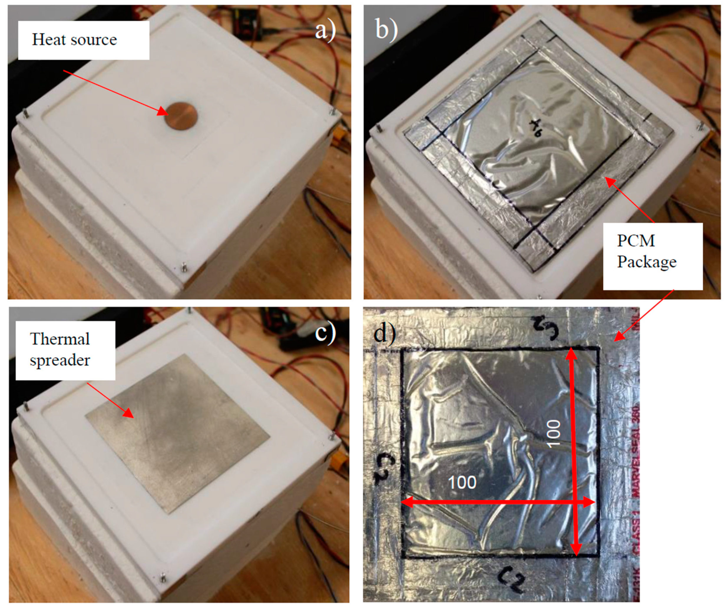
Figure 1. A photograph of the setup is visible in
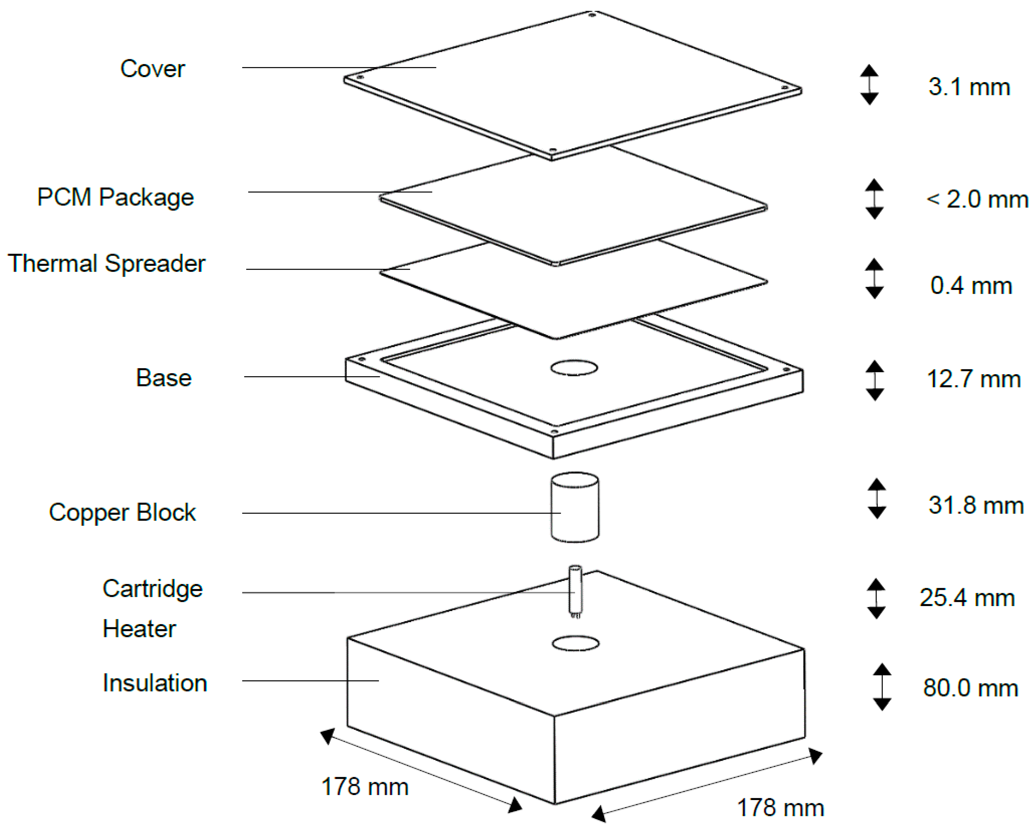
Figure 2. The setup is made of a discrete heat source, a 25.4 mm diameter copper block with a length of 31.75 mm mounted in the middle of the base. A 6.35 mm diameter, 25.4 mm long, cartridge heater (Nordic Sensors, custom made), which can provide up to 12 W of power, is inserted in the middle of the block. This heat source mimics heat dissipation from a tablet computer’s SoC. The copper block is in the middle of the setup and flush with the Teflon base that simulates a tablet computer’s housing. The square Teflon base has a side length of 178 mm and a thickness of 12.7 mm. A square cavity with a depth of 2 mm and a side length of 152.4 mm is poured on the upper surface of the base. The base forms a small cavity enclosed by a cover made of nylon with a thickness of 3.1 mm. This small gap is filled with the thin PCM package with a mean thickness of less than 2 mm. Finally, the cylindrical heat source is surrounded by insulation (
k = 0.06 W/m·K), which forces generated heat to move through the base and the tested PCM package. The dimensions of the entire setup are: 177.8 mm on each square side and 115 mm in height. The thermal properties of nylon, Teflon, and copper are given in
Table 1.
A DC voltage supply (type Statco Energy 3PN501B) is used as a power source. An analog output NI9263 (0–10 V) module controls the power source via LabView 2014. During each experiment, the voltage input of the DC supply was measured using an analog input NI9201 module. The current through the heater was determined by measuring the voltage drop over a shunt resistor RShunt (type HSA25R05J, 0.05 Ω), which is placed in series to the heater. Finally, the power input was determined by multiplying the current and the voltage input. The expanded measurement uncertainty of the power input was ±7%.
The temperatures of the PCM package, the temperature of the heater and the ambient (
T∞), as well as the electrical power (
P) input were measured during all experiments. Five T-type thermocouples (
TC, see
Figure 3) were used to measure the temperatures at different locations of the top of the nylon cover. Four T-type thermocouples (
TU1–
TU4) were mounted on the upper surface and five T-type thermocouples (
TL1–
TL5) on the lower surface of the PCM package. The heater block temperature,
TH, was measured using a 1.6 mm (1/16 in) diameter steel T-type thermocouple probe.
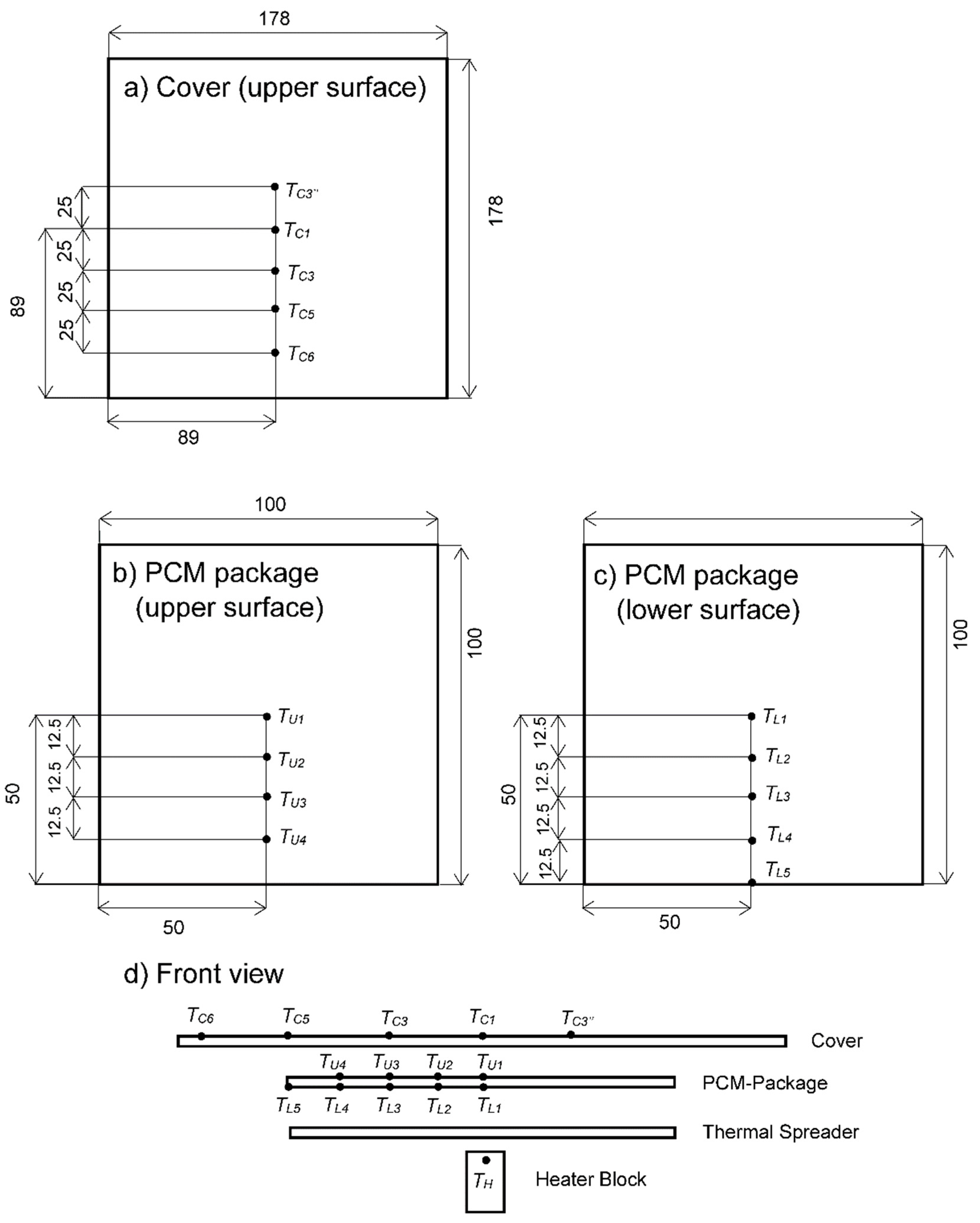
Figure 3 illustrates the location of the temperature sensors mounted on the PCM package. The thermocouples were mounted using thin high-temperature kapton (polyimide film) tape (0.07 mm,
k = 0.2 W/m·K). The thermocouple manufacturer’s stated accuracy was verified to be within the range of ±0.5 °C using a Fluke Micro-Bath 7102. During the experiments, continuous data acquisition was accomplished at 1 Hz with the use of an NI cDAQ-9174 and an NI 9213 16-port thermocouple module operated via LabView 2014.
The main selection criterion for PCMs for this study was their melting temperatures. Sponagle et al. [
36] showed numerically that PCMs with melting points between 35 and 41 °C provide very good transient performance by nearly fully melting during 30 min of operation. Based on these numerical studies, two PCMs were selected:
n-eicosane (technical grade paraffin) and dodecanoic acid, a fatty acid.
Table 2 summarizes the physical properties of both PCMs. Those two PCMs have similar physical properties but different melting points. Hence, they allow an investigation of the influence of different melting temperatures on the performance. These materials were chosen since they are nontoxic, and do not show any corrosive effects when in contact with aluminum. Furthermore, these materials have been used in many research projects, their physical properties are measured and their long-term stability has been proven in previous work for up to 4000 melt–freeze cycles [
37,
38]. Both values of the properties and the uncertainties listed in
Table 2 are adopted from these publications.
Two PCM packages were fabricated from two 120 × 120 mm aluminized films, which were heat sealed along a 10-mm border. The pocket therefore had dimensions of approximately 100 × 100 × 2 mm filled with PCM. A mold consisting of two parallel plane aluminum sheets separated by a distance of 2 mm was used for filling of the PCM packages. The empty packages were sealed on each side except for the top and mounted into the 2-mm gap of the mold. This was then placed into a water bath (temperature between 45 and 50 °C) and the liquid PCM was inserted into the package using a syringe. Once filled, the top seam was sealed. The filling mass and the type of PCM used in the packages are summarized in
Table 3.
Table 3 also shows the latent storage capacity of both PCM packages, as well as the total storage capacity (latent plus sensible taken over a 50 °C temperature increase, which is representative of the order of magnitude observed in the experiments) for both packages.
Although n-eicosane has a larger latent heat, with its higher heat capacity, dodecanoic acid ends up storing approximately the same amount of energy over a 50 °C temperature increase (that includes melting).
Heat-sealable aluminized film (Marvelseal 360, Class 1) was used to encapsulate the PCM. This film is composed of a thin aluminum layer sandwiched between a nylon and a polyethylene layer, having a total thickness of 0.132 mm. A thin square aluminum (thermal conductivity of 167 W/m·K) sheet (100 × 100 × 0.4 mm) was used as a thermal spreader. The side length of the thermal spreader (100 mm) is identical to the side length of the square filled PCM package.
4. Results
4.1. Experiments Without Thermal Spreader
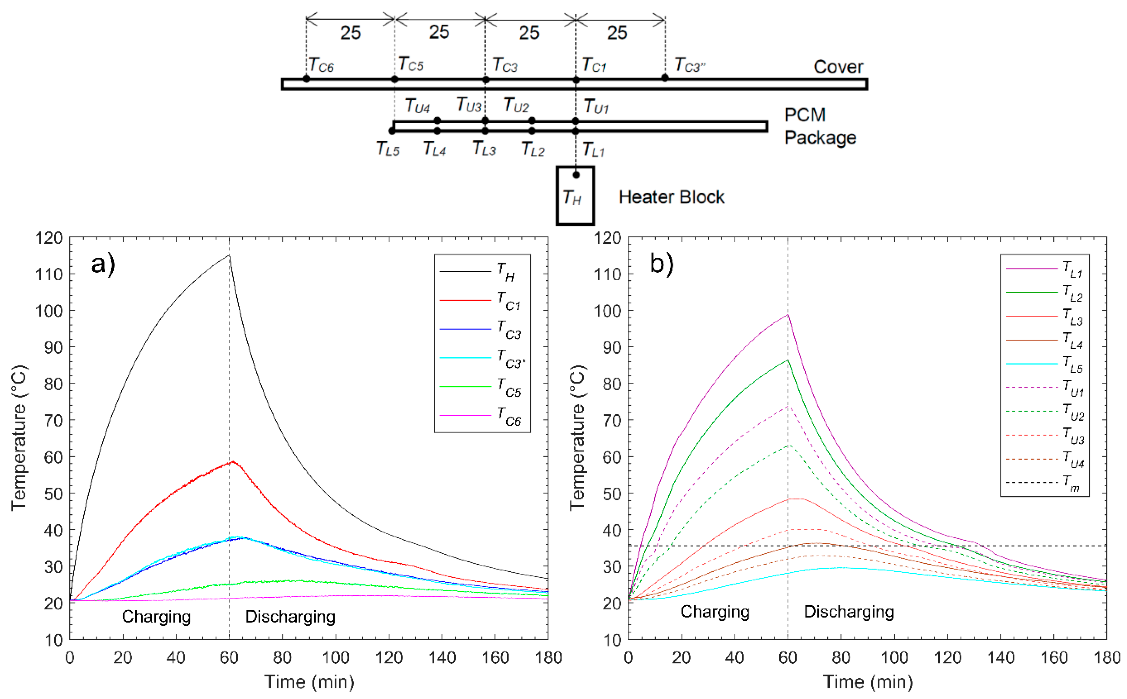
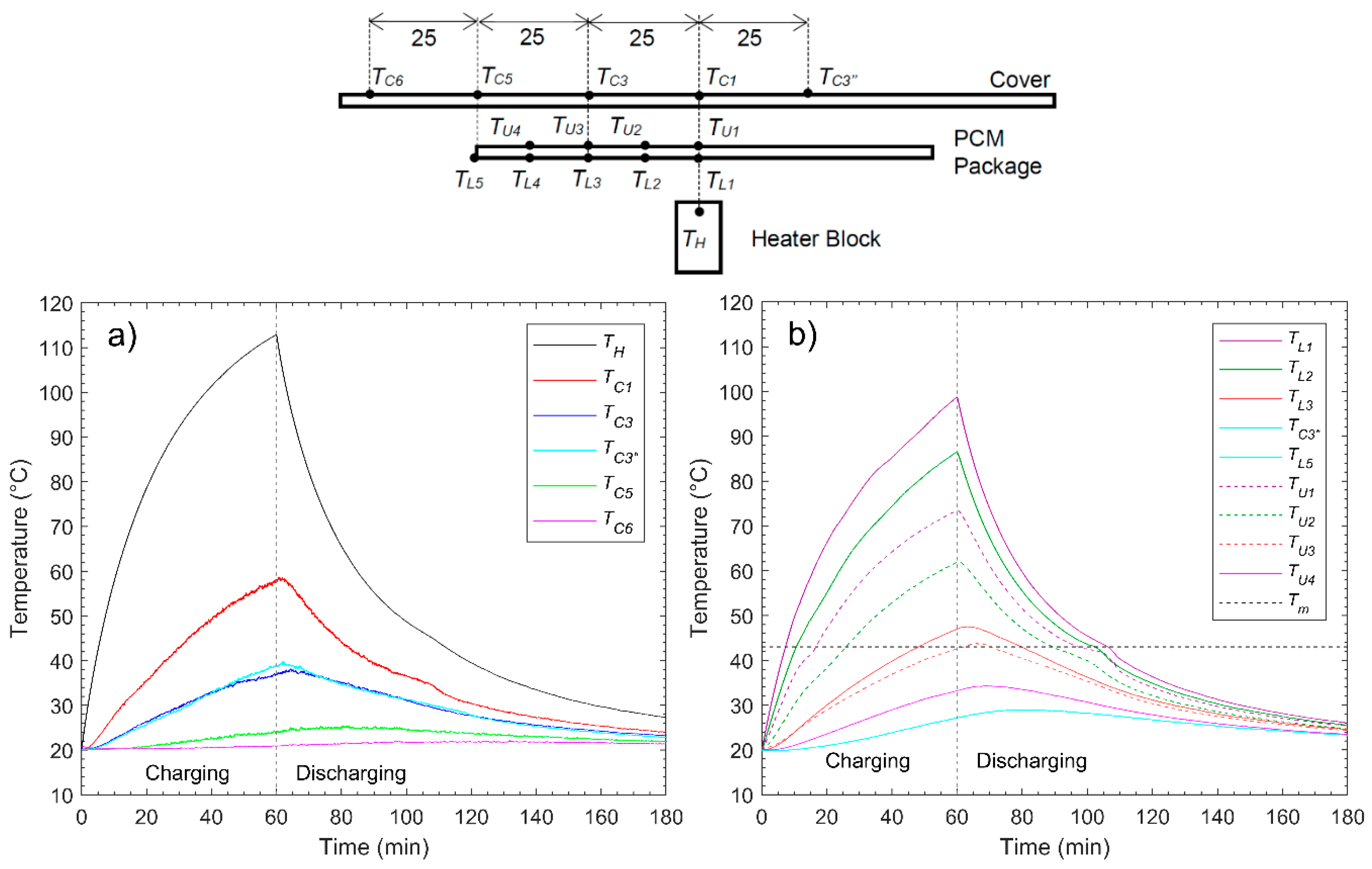
Figure 4a presents the measured temperature profiles of the heater (
TH) and the cover surface (
TC) for the experiment with package A (
n-eicosane).
Figure 4b shows the temperatures on the PCM package at various positions on the upper and lower surface. The temperatures read by the thermocouples located at the upper surface of the package (
TU1–
TU4) are illustrated in dashed lines, the ones located at the lower surface in full lines (
TL1–
TL5). The temperatures measured with the thermocouples with equal radial distances to the center (for example,
TU2/
TL2) are plotted in the same color. The melting temperature,
Tm, of
n-eicosane is drawn as a dashed black line in the figure.
At time zero, heat was generated from the heat source, resulting in a temperature increase of all thermocouples from their initial value, which was approximately 20 °C (room temperature). A maximum heater temperature of 115 °C was reached after 60 min. It is observed that the further the radial distance of the thermocouples to the heater, the lower the temperature increase was, showing that the package provides a very small amount of heat spreading above the bare setup case. The maximum temperature of the cover surface at the center of the setup was 58.5 °C after 60 min of charging. The temperatures of the thermocouples TC3 and TC3’, which were placed on the cover at equal radial distance to the center, are very similar during both charging and discharging. In fact, the difference is within the measurement uncertainties of the thermocouples, which indicates the symmetrical nature of the experiment.
When comparing the curves of the two temperature sensors mounted on the PCM package at equal radial distance to the heater, e.g., TL1 and and TU1, it is observed that the temperature increase on the lower surface was greater than the one at the upper surface. After 4.5 min, TL1 reached the melting temperature of 35.6 °C. It took 11 min until TU1 reached the melting temperature.
It may therefore be assumed that the PCM located closest to the center melted during this time span (4.5 to 11 min). TL3, which is the temperature of the lower surface of the PCM package at a radial distance of 25 mm to the center, reached the melting temperature after 28 min. TU3, on the upper surface of the PCM package at an equal radial distance to the center as TL3, reached the melting temperature after 45 min. Accordingly, it may be assumed that the melting front of PCM reached a radius of 25 mm within the time span of 28 to 45 min. TU4 and TL5 did not increase above the melting temperature, which indicates that the whole PCM did not melt during the experiment due to poor spreading within the PCM package, which shows that the low thermal conductivity of the PCM dominates over any possible heat spreading offered by the thin aluminized film making the package.
The measured temperatures of the heater (
TH) and the cover surface (
TC) for the experiment with package B (dodecanoic acid) are illustrated in
Figure 5a. PCM package B has the same volume and almost the same storage capacity as PCM package A, but its melting temperature is 7.4 °C higher than the one for package A. The temperature profiles of the upper (
TU1–
TU4) and lower (
TL1–
TL5) surface of PCM package B are shown in
Figure 5b.
It is observed that the shape of the temperature profiles does not differ a lot from the experiment where PCM package A was used. A maximum heater temperature of 115 °C was reached after 60 min. The maximum temperature of the cover surface at the center (TC1) of the setup was 58.5 °C after 60 min of charging. TC6, which is located at the greatest distance to the center, only increases by 1.6 °C, showing a similar absence of heat spreading with the added package. TL3, which is the temperature of the lower surface of the PCM package at a radial distance to the center of 25 mm, reached the melting temperature after 48.5 min. TU3, which is the equivalent temperature located on the upper side, reached the melting temperature after 63 min. The temperatures with a further radial distance than 25 mm did not increase above the melting temperature. Accordingly, the melting front did not reach the position of TU4 and TL4. Comparing the temperature profiles measured on the package surface for package A and B, a smaller amount of PCM melted in package B (dodecanoic acid with the highest melting temperature) since the spread of temperatures reaching the melting temperature of the PCMs as measured on the surface does not extend as far. This is logical based on the highest melting temperature of the PCM.
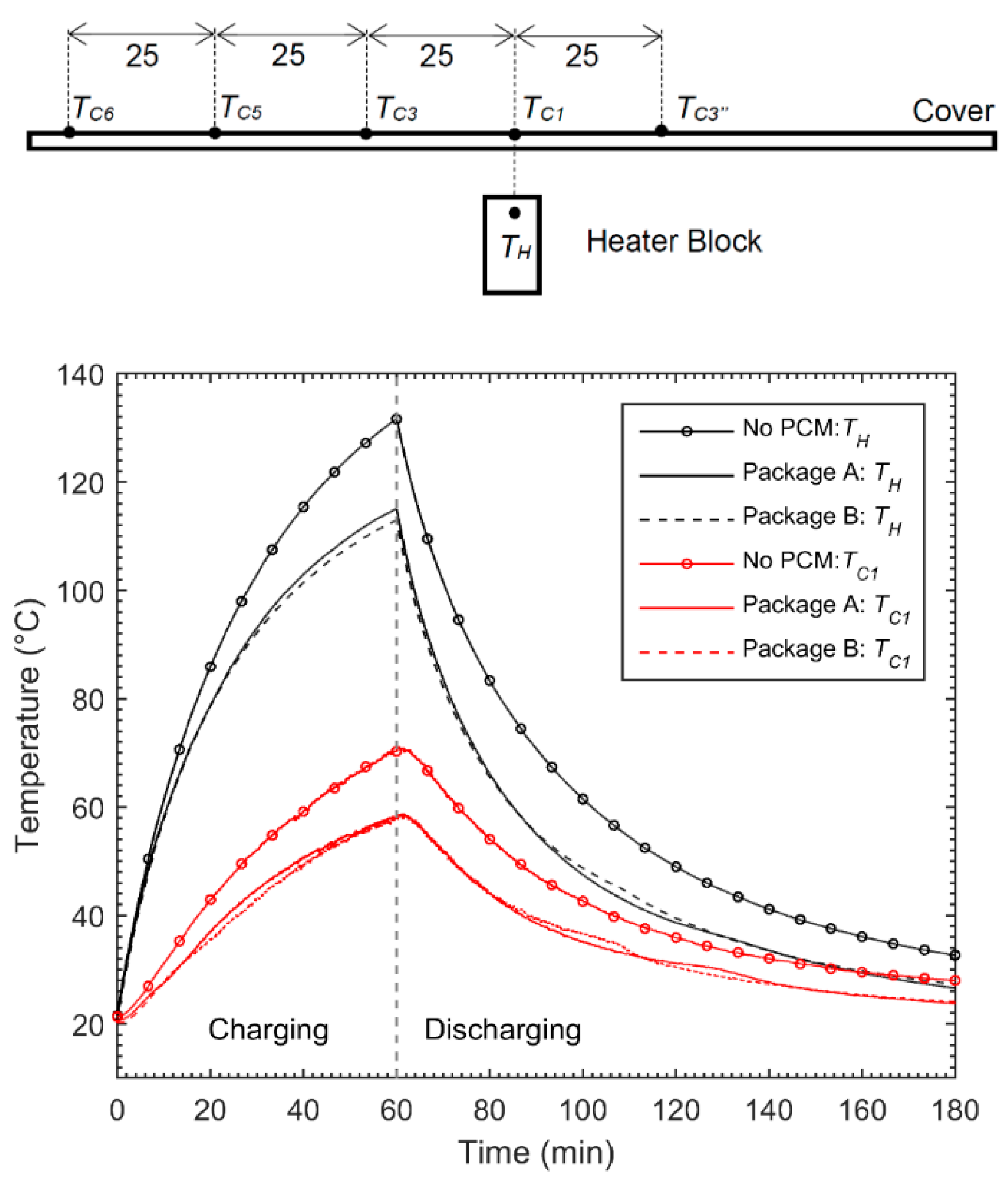
In order to compare the influence of adding the PCM packages to the thermal performance of the setup, the experiment was also performed without the addition of any PCM package.
Figure 6 illustrates the temperature profiles of the heater,
TH, and the cover surface,
TC1, for all three experiments. Only these temperature curves are illustrated since most of the heat was transferred in the axial direction along the center of the setup. Hence, these temperatures represent the maximum temperatures of the heater and the cover surface.
As visible in
Figure 6, both the heater and the cover temperatures were higher during the entire charging and discharging process when no PCM package was used compared to the cases with PCM packages. More specifically, the maximum heater temperature after 60 min of charging was 15 °C lower for PCM package A and 17 °C lower for PCM package B compared to the experiment without the PCM package. The peak temperature of the cover was reduced by 14 °C for both PCM packages.
There are mainly two different effects that cause the reduction of the peak temperatures of both the heater and the cover when a PCM package was used. First, the thermal conductivity of the air in the cavity (0.024 W/m·K) is lower than the thermal conductivity of both PCM packages (0.46 W/m·K for the solid PCM in package A, 0.15 W/m·K for the solid PCM in package B). The lower thermal conductivity of air created a higher resistance for the heat to dissipate from the heater. Since the heat input for all three experiments was the same, the increased resistance led to a greater increase of the heater temperature when no PCM package was used. Moreover, the low thermal conductivity of air minimizes the thermal spreading of heat in the radial direction. The second effect that causes the difference in peak temperatures lies in the fact that the storage capacity of the cavity between the heater and cover increases massively when adding the PCM packages (approximately 3600 J for a considered temperature difference of 50 °C). The thermal heat capacity of air is only 1 J/g∙K. Thus, the heat input resulted in a large temperature increase of the air volume in the cavity between the base and the cover. When a PCM package was used, the storage capacity of the cavity is much higher due to the latent heat capacity that may be stored during melting. Accordingly, the same energy input led to a smaller temperature increase of the volume between the heater and the cover. This, in turn, led to a reduction of both the heater and the cover temperature compared to the no PCM case since some of the energy was stored in the PCM during the transient charging and did not have to be readily evacuated to the surface.
4.2. Experiments with Thermal Spreader
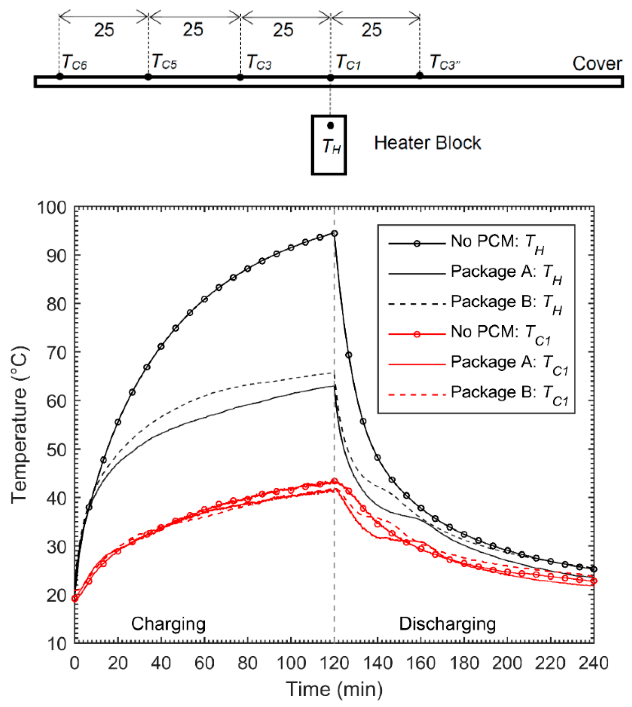
The experimental results presented in the previous section showed that installing PCM packages led to a reduction of both the heater and cover peak temperatures. In this section, the experiment with a thermal spreader (thin aluminum sheet with a thickness of 0.4 mm) will be presented. For each experiment, the thermal spreader was placed on top of the heater. The same PCM packages as in the previous experiments were used and placed above the spreader. For each experiment, a constant heat input of 5 W for 120 min was applied.
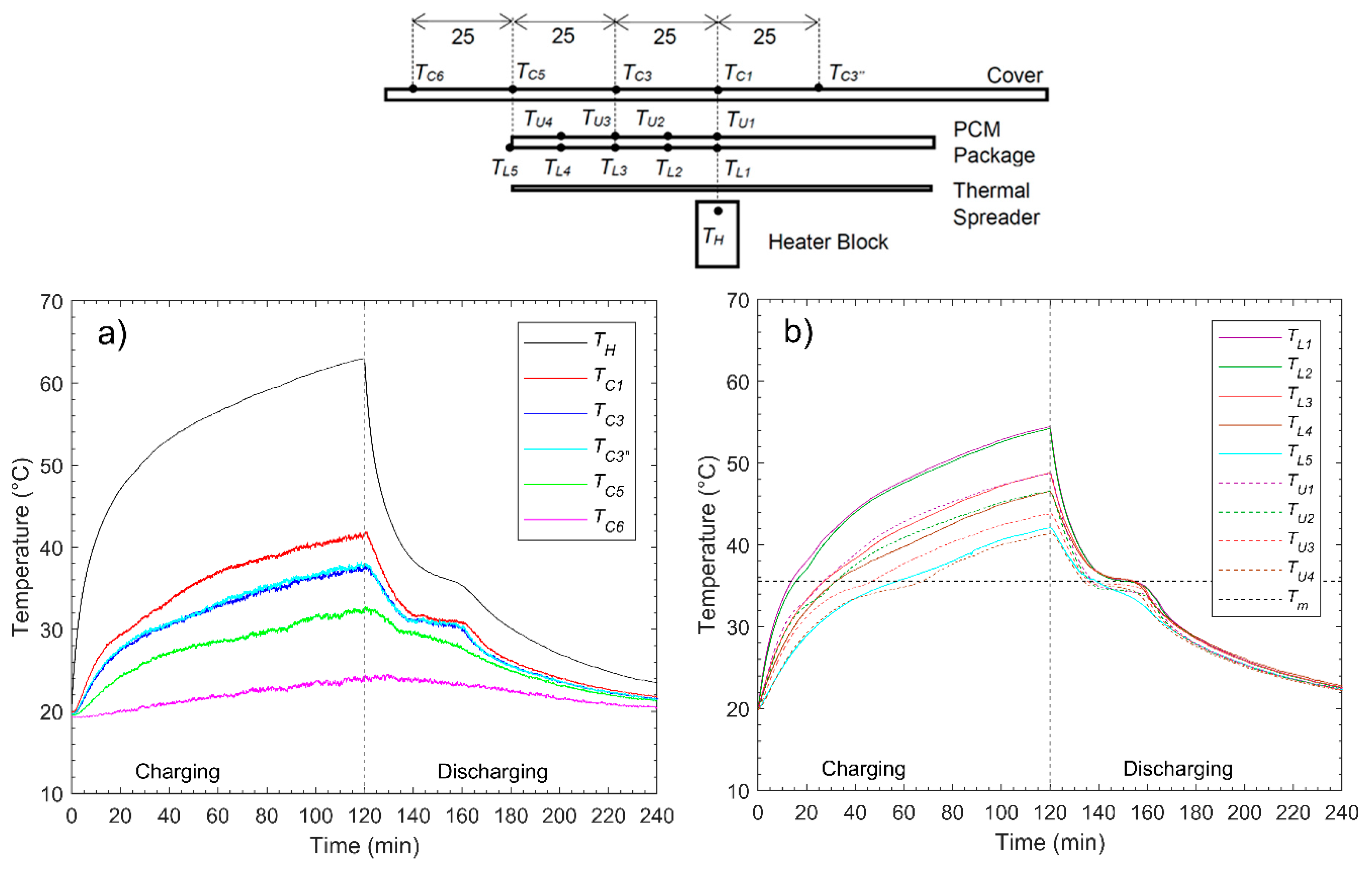
Figure 7a presents the measured temperature profiles of the heater (
TH) and the cover surface (
TC) for the experiment with package A (
n-eicosane) and the spreader.
Figure 7b shows the temperature profiles of the PCM package at the various positions on the upper and lower surface.
The maximum temperature of the heater was 63 °C after 120 min of charging. The maximum temperature of the cover was observed to be 41.8 °C. The lower temperatures of both the heater and surface points to the usefulness of the thermal spreader, which moves part of the heat produced from the heater to the further corners of the system, enabling the reduction in the temperature of the warmest hot spot on the surface and an increased rate of energy storage in the entire PCM. To that last point, it is observed that the temperature profiles of all the installed sensors on the PCM package increased above the melting temperature within the charging time of 120 min, which indicates that all of the PCM melted during the experiment. It is also noticed that all those recorded temperatures had reached the melting point of the PCM after 60 min, which was not achieved in the previous experiments without the spreader. Therefore, the thermal spreader distributed the heat coming from the heater mostly in the radial direction. The shape of the temperature profiles, in particular during the discharging process, were much different compared to the experiment where no spreader was used. All of the temperature profiles, except TC6, showed a clear plateau where the temperature stayed nearly constant.
This observation is caused by the fact that all the PCM melted, and therefore, during cooling, all of the PCM must solidify; the plateau is a sign of the isothermal phase transition (solidification) of the PCM. During the phase transition, the stored latent heat in the PCM is released and conducted to the cover of the setup at a nearly constant temperature. During the additional time span when the PCM is solidifying (plateau), the surface temperature of the system remains higher, which also leads to increased overall heat transfer by convection from the surface, since the temperature differential remains higher for a longer period. This helps explain why it takes approximately the same amount of time to bring the system back to its original state (room temperature), even though much more energy was generated by the heater and more of it was stored in the PCM.
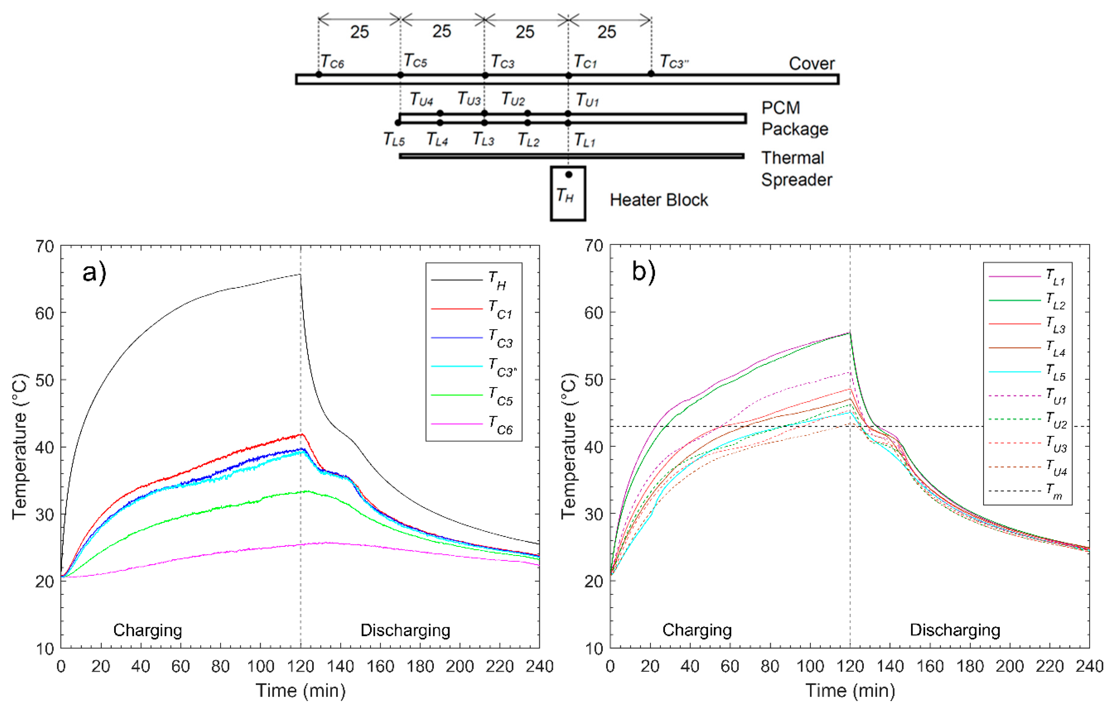
Figure 8a presents the measured temperature profiles of the heater (
TH) and the cover surface (
TC1–
TC6) for the experiment with package B (dodecanoic acid) and the spreader.
Figure 8b shows the temperature profiles of the PCM package at the various positions on the upper and lower surface.
The heater reached a maximum temperature of 65.7 °C after 120 min of charging. The maximum cover temperature was 42 °C after 121 min. During the charging process, the temperature profiles did not differ much compared to the experiment with PCM package A, and the same conclusion can be drawn with one exception: Since dodecanoic acid has a higher melting temperature, it took until the end of the experiments (120 min) to fully melt all of the PCM in the system, compared to approximately 60 min in the case of n-eicosane. This is enough of a difference in the overall behavior to explain the difference of a few degrees in the temperature of the heater.
The experiment with the thermal spreader was also performed without PCM.
Figure 9 compares the measured temperature profiles of the heater and the center cover surface for the experiment without any PCM package, PCM package A, and PCM package B.
As illustrated in
Figure 9, the maximum heater temperature and the maximum cover temperature were reduced by adding PCM packages compared to the experiment where no PCM package, but the thermal spreader only was used. In fact, the peak temperature of the heater was reduced by 31.5 °C when package A was used and 28.8 °C when PCM package B was used. The maximum cover temperature was reduced by 2.2 and 1.7 °C, respectively. As mentioned above, the reduction of these peak temperatures was mostly due to the increased thermal storage capacity when a PCM package was installed. In
Figure 9, the heater temperature is similar in all three experiments during the first 15 min of charging. Once the PCM in the packages started to melt, the increase of the heater temperature lessened compared to the case where no PCM package was used. Additionally, the air gap between the thermal spreader and the cover presents a larger thermal resistance compared to the case when a PCM package was used and thus led to a large temperature increase of the thermal spreader and the heater.
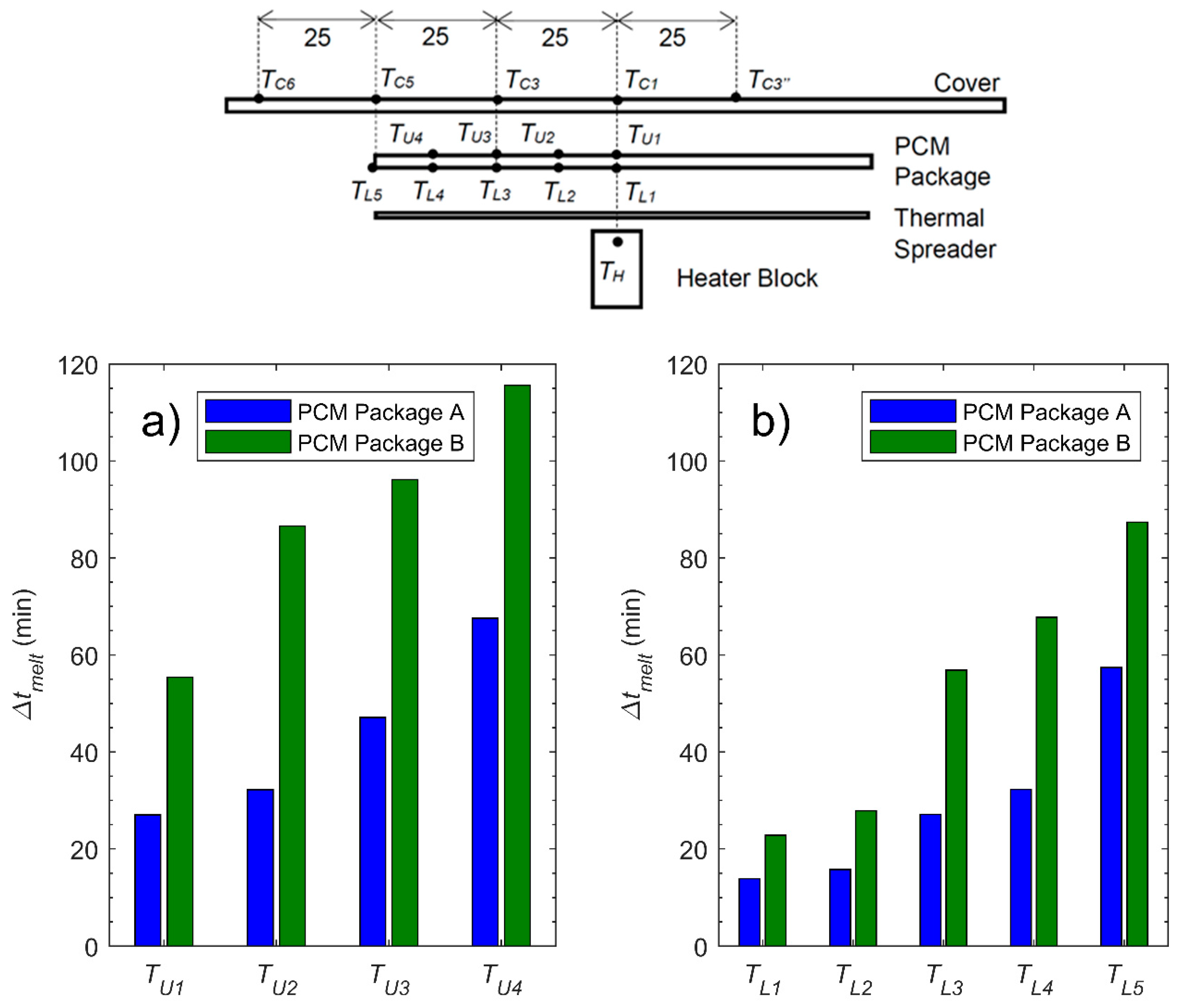
When comparing the temperature profiles obtained with PCM package A and PCM package B, one sees that the increase of the heater temperature was slightly higher for PCM package B, where the measured temperature profiles of the cover temperature were almost identical. It is assumed that this difference was due to the higher melting rate when PCM package A was used compared to PCM package B. The melting rate can be analyzed by comparing the time intervals,
Δtmelt, between the start of the experiment and the point in time when the temperatures of the surface of the PCM packages have reached the melting temperatures. The obtained
Δtmelt are illustrated in
Figure 10 for each temperature sensor and for both experiments with PCM package A and B.
The comparison of
Δtmelt illustrated in
Figure 10 indicates that PCM package A experienced a higher melting rate than PCM package B. This was expected, since PCM package A consists of a lower melting temperature PCM than the PCM in package B; this was also observed for the experiments without the thermal spreader. Thus, latent heat was stored more rapidly when package A was used compared to the case when package B was used. The PCM in package A also had a higher latent heat of fusion. However, no difference was observed for the cover temperature. This might be because the PCM in package B had a higher specific heat capacity in the solid phase (1.95 kJ/kgK) compared to the PCM in package A (1.8 kJ/kgK). Assuming that the PCM in both packages realized a temperature increase of 28 K, which was approximately the temperature difference between the temperature at the beginning of the charging process and the end of the charging process during the experiments with the spreaders, the sensible heat absorbed by the PCM in package A was approximately 599 J and the sensible heat absorbed by the PCM in package B was 705 J. Thus, it may be concluded that in the case of package B, more heat was stored sensibly compared to the case of package A, where more heat was stored latently.
4.3. Overall Comparison of the Performed Experiments
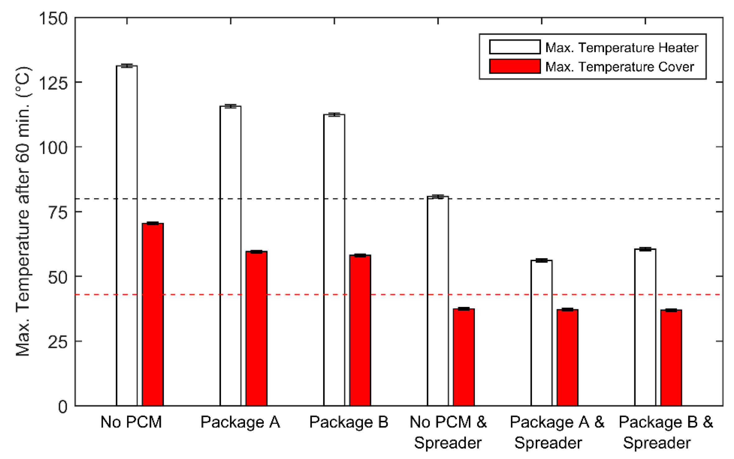
In order to compare the different experiments with regard to their potential use as an efficient thermal management system, the maximum heater temperature and the maximum cover temperature after 60 min of charging with 5 W are compared in
Figure 11. The error bars indicate the measurement uncertainty of the thermocouples. The operation temperature upper limits of the electronic parts (80 °C) and the cover (43 °C) of a real tablet are drawn as dashed lines in
Figure 11.
The comparison illustrated in
Figure 11 shows that the lowest peak temperature of the heater was obtained when the thermal spreader and the PCM package A was used. The maximum heater temperature after 60 min was reduced by 75 °C compared to the case where no PCM package and no thermal spreader were used. Furthermore, the results above clearly illustrate that the addition of a thermal spreader led to a drastic reduction of the temperature increase of the cover surface. The peak temperature of the cover was reduced by approximately 33 °C for all the experiments where a thermal spreader was used. Adding the thermal spreader increases the heat distribution in the radial direction and reduces the hot spot in line with the heater. Accordingly, the heat is spread over a larger surface when compared to the case when no spreader is used. That leads to more melting and accordingly more heat may be absorbed by the PCM, which leads to a smaller temperature increase of the cover surface.
The effect of the thermal spreader may be analyzed by comparing the results of the experiment with PCM package A without a spreader and PCM package A with a spreader. Since the absolute storage capacity of the cavity between the heater and the cover did not differ much between those two experiments (approximately 4106 J for PCM package A with a spreader and approximately 3600 J for PCM package without a spreader), the comparison allows a demonstration of the influence of thermal spreading.
Figure 12a shows the temperatures of the lower surface of the PCM package (
TL1–
TL5) after 60 min against the radial distance of the thermocouples for both experiments.
Figure 12b shows the resulting temperatures of the cover surface (
TC) after 60 min against the radial distance of the thermocouples for both experiments.
Due to the presence of the thermal spreader, the heat was distributed in the radial direction, which led to a more uniform temperature profile along the radial distance to the center compared to the case where no spreader was used, as visible in
Figure 12a. Moreover, the distribution of heat led to additional melting, which also led to a more uniform temperature distribution of the PCM package compared to the case without a spreader, as illustrated in
Figure 12b.
5. Conclusions
The primary objective of this work was to directly investigate the thermal behavior of thin PCM packages and the combination of thin PCM packages with a thermal spreader. In order to characterize thin PCM packages and its combination with a thermal spreader, a set of experiments on a simplified setup with a constant heat power input were performed. Such a setup needed to be used to isolate the thermal behavior of the PCM packages, since a proper understanding of the behavior of PCM packages is impossible to fully isolate when used and studied in a real portable electronic system (including the screen, battery, and other complex internal components). This study is therefore the first one focused solely on the PCM package.
An appropriate passive cooling system, which may be integrated in electronic devices, has to limit the temperature increase of heat-producing parts while keeping the cover surface within a comfortable temperature range. Therefore, it was particularly of interest to experimentally investigate the behavior and ability of PCM packages to reduce the peak temperatures of both the discrete heat source and the cover surface of the setup.
Two different types of PCM were used: n-eicosane, a paraffin with a melting temperature of 35.6 °C, and dodecanoic acid, a fatty acid with a melting temperature of 43 °C. Thin heat-sealable aluminized film was used to encapsulate the PCM. The first set of experiments were performed with PCM package A (n-eicosane) and PCM package B (dodecanoic acid) without a thermal spreader. A constant power input of 5 W for 60 min was applied. It was observed that both PCM packages reduced the maximal heater temperature by 15 (package A) and 17 °C (package B) compared to the case where no PCM package was used. The maximum cover temperature was reduced by approximately 14 °C for both PCM packages. Furthermore, it was observed that both PCM packages did not melt completely during the charging process since heat was mostly transferred in the axial direction, although package A experienced a higher melting rate than package B due to its PCM’s lower melting temperature. The PCM encapsulated in thin aluminized film therefore offered very little heat spreading capability, still leading to a hotspot on the cover of the system.
The experiments confirmed that the inclusion of the heat spreader reduced both the peak heater and cover temperature by spreading this hotspot over a wider area. By facilitating lateral conduction, the spreader both increased the thermal mass of the PCM activated for thermal storage and the cover area available for convection. The use of both the heat spreader and PCM proved even more effective at reducing the temperature of the heater while maintaining a low cover temperature. The spreader and PCM was superior to either solution alone. Latent and sensible storage of the PCM increases the apparent thermal mass of the setup and the spreader facilitates the heat accessing that thermal mass. During the experiments with the PCM package and spreader, all of the thermocouples mounted on the PCM package showed a temperature increase above the melting temperature of the PCM used, which indicated that, most likely, the complete PCM melted. Furthermore, the experiment showed that PCM package A with a thermal spreader provided a slightly better performance than PCM package B. The overall comparison showed that when PCM package A and a thermal spreader were used, the temperature peak of the heater after 60 min of charging was reduced by 75 °C compared to the case where neither a spreader nor a PCM package were used. The maximum cover temperature was reduced by 33 °C. It is still important to note that today’s portable electronics use antennas to remain in contact with the outside world (through the internet and cell phone technologies); so, in a complete design approach, a poorly designed spreader could create impractical interference with the said antenna and disrupt the communication operations of the device.
In summary, it can be concluded that the experiments performed in this work have shown that the combination of a thermal spreader and a thin PCM package has strong potential to be used as part of a passive thermal management system in thin portable electronic devices since the use of both components led to a more efficient use of the full PCM mass (larger amount of PCM melting) and a reduction of the central hotspot temperature by increased thermal spreading. The studied system fulfills the spatial requirements of thin portable electronic devices and may provide the ability to reduce overheating of both electronic components and the cover surface.


