Abstract
We develop a method to lock a high-finesse near-unstable Fabry–Perot (FP) cavity (F = 7330) to a frequency stable dye laser operating at 605.78 nm using the Pound–Drever–Hall technique. The experimental results show the feasibility of locking this cavity to different transverse modes. This method links the external FP cavity to the dye laser cavity, and a 379 kHz final linewidth of the FP cavity is achieved. Such a near-unstable cavity is potentially useful for cavity-enhanced spontaneous parametric down-conversion to generate narrow-band single photon or photon pairs in different transverse modes.
1. Introduction
In the development of narrow-band entangled photon-pair sources for applications such as quantum storage and quantum information processing [1], high-finesse optical cavities have been used to enhance the spontaneous parametric down-conversion (SPDC) [2,3,4,5,6,7,8]. This method was proposed by Ou et al. in 1991 [2], and generates entangled photon pairs using a second-order nonlinear effect and narrows the linewidth of single photon pairs by putting the nonlinear crystal inside the optical cavity. The narrow spectral linewidth of SPDC has been achieved in various types of cavities, for example, bow-tie cavity [6,7,8,9,10,11] and the Fabry–Perot (FP) cavity [4,12,13,14,15,16]. The bow-tie cavity consists of four mirrors with a long cavity length for a narrow spectral linewidth. It is expensive and is sensitive to the environmental perturbation due to the long cavity length. The FP cavity usually consists of two components, a mirror and a nonlinear crystal with a highly reflective coating on the output surface with a curvature. The FP cavity and periodically poled crystals have been successfully used for narrow-band polarization-entangled photon pair generation [4]. However, the performance of this kind of FP cavity is limited by the coating technology for a high-finesse because most nonlinear crystals, e.g., Beta-Barium Borate crystal (BBO) and Potassium Dihydrogen Phosphate crystal (KDP), cannot be coated with highly reflective films. Three-component cavity solves this problem by putting the nonlinear crystal in the cavity for SPDC. In a three-component FP cavity, it is easy to replace the nonlinear crystal and the cavity is suitable for both type-I and type-II cavity-enhanced SPDC, where the type-I and type-II refer to the phase-matching conditions of the nonlinear crystal. In type-I, the down-converted photons are either in extraordinary rays (e rays) or ordinary rays (o rays), and their polarizations are orthogonal to the pump polarization [3]. While in type-II, the polarizations of the down-converted photons are orthogonal [4]. The selection of FP cavity type is crucial in generating entangled photon pairs. For example, confocal cavity is a kind of widely used cavity since it is highly stable and easy to align. However, it has a relatively low threshold when using a nonlinear crystal as the gain media for SPDC. With the gain media, the cavity is called optical parametric oscillation (OPO) cavity. The narrow-band entangled photons can only be generated in a condition of far-below threshold, and the OPO cavity will be lasing above the threshold. Therefore, working at far-below threshold is crucial for cavity-enhanced SPDC [2].
In this paper, we designed a kind of near-unstable FP cavity, which is away from the confocal region but close to the stability boundary of cavity. Similar near-unstable cavities were recently proposed for gravitational wave detection [17]. In their case, a larger beam spot size on the mirrors is required to reduce the mirror coating thermal noise. We intentionally selected the near-unstable cavity due to its relatively high threshold when using it in OPO, therefore the far-below threshold condition can be easily achieved. The FP near-unstable cavity consisted of a plane mirror and a concave mirror with a large radius. It is difficult to lock this kind of cavity with an ultra-high-finesse for an extremely narrow linewidth. We used the Pound-Drever-Hall (PDH) technique to lock the designed FP cavity in both the fundamental mode and the high-order transverse modes and dynamically linked a high-finesse external FP cavity (F = 7330) to the dye laser cavity at the same wavelength of sub-megahertz narrow linewidth. As a proof of principle, we locked the cavity at the wavelength of 605.78 nm, which matches the hyperfine energy-level transition of ion in : crystal and has many potential applications such as quantum storage and quantum information processing [18,19]. Such cavity is also potentially useful to generate sub-megahertz narrow-band degenerate single photons and to improve the single-photon generation rate of SPDC. When locking the cavity in different transverse modes, one can generate single photons within the same transverse modes, which can be used in quantum lithography and quantum imaging.
2. The Stability Condition of Near-Unstable Cavity
The optical cavity we chose was a specific FP cavity consisting of two mirrors, one was a plane mirror M1 and the other was a concave mirror M2 with a curvature radius . The distance between the two mirrors, i.e., the optical cavity length L, was 54 mm. Figure 1 shows the mode-matching scheme and parameters of this cavity.
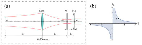
Figure 1.
(a) is the mode-matching scheme for the FP cavity. M1 is a plane mirror with a curvature radius . M2 is a concave mirror with a curvature radius . The different sides of mirrors M1 and M2 are denoted by a, b, c, and d, respectively. is the radius of the incident Gaussian beam, is the waist radius of the light beam on the front surface a of M1, and is the radius of the light beam on the front surface c of M2, respectively. (b) is the stability diagram of the coaxial spherical cavity. The shadow region is the stable region while the empty, white region is the unstable region. Point A ( and ) is the location of our cavity close to the boundary between the stable and the unstable regions.
The stability condition of the resonant cavity can be written as [20]
where and . In this experiment, , similar to the case of gravitational wave detection [17]. The stability diagram of the coaxial spherical cavity is shown in Figure 1b, where the shadow region is the stable region and the empty white region is the unstable region. Our cavity is located at point A in the stability diagram as shown in Figure 1b. For the reason that is close to 1, the cavity reveals some characteristics of a near-unstable cavity. The free spectral range and the transverse mode spacing can be calculated using Equation (2), which is 2.78 GHz and 296 MHz, respectively. Compared to the stable cavity, the near-unstable cavity is unique for its small transverse mode spacing and therefore allows for more high-order transverse modes within a free spectral range. In our case, we obtained about nine transverse modes having the same axial mode index. It is useful for transverse mode tuning. This feature suppresses the laser generation while the cavity is still lockable, which is essential for the OPO cavity to work at the far-below threshold condition. On the other hand, the cavity cannot be too close to the unstable boundary. This is because when the transverse mode spacing is close enough to the modulation frequency, the sideband will overlap with neighboring transverse modes and disturb the locking performance based on PDH technique. As for a cavity located on the unstable boundary, the transverse modes are degenerate, and it is hard to lock a single transverse mode when used for OPO experiments.
3. PDH Technique in Cavity Stabilization for Different Transverse Cavity Modes
Due to mechanical vibration of mirror mounts, temperature drift, air flows, and frequency shift of the incident laser, the optical cavity suffers a frequency drift and line broadening. There are various methods to lock the cavity, for example, the side of fringe stabilization technique [21], the PDH stabilization technique [22,23], the Hansch-Couilaud technique [24], and the tilt-locking technique [25]. The side of fringe stabilization technique can only lock the cavity to the side of transmission or reflection peak, whereas it is not the optimal position of the cavity. The Hansch-Couilaud technique requires a nonlinear crystal cut at the Brewster angle or putting a polarizer in the middle of the cavity to alter the polarization of the incident light, which may reduce the finesse of the cavity. The tilt-locking technique takes the advantage of the interference among different spatial modes and needs split detectors with a high position precision [26]. Compared to the above mentioned techniques, the PDH stabilization technique is stable, easy to operate, and capable of operating continuously for a long time.
While most PDH stabilization experiments are focused on locking the fundamental cavity mode, high-order transverse cavity modes may be useful for some specific cases, for example, using the higher-order Laguerre-Gauss modes to reduce the contribution of coating Brownian noise for gravitational wave detection [27,28,29,30]. For type-I SPDC, the down-converted photons are distributed on a down conversion ring. If locking the cavity in the fundamental mode, the two entangled photons may leave the cavity collinearly and only one light spot can be observed. On the other hand, if locking the cavity in a high-order Hermite-Gaussian mode, e.g., the mode, the generation rate of entangled photons can be enhanced by the cavity in two different directions. In this way, the enhanced SPDC occurs in a specific down conversion angle. For different cavity modes with m and n being the horizontal and vertical orders of the transverse mode and q being the order of the longitudinal mode, respectively, the resonant frequency of each mode is related to not only the longitudinal mode number but also the transverse mode numbers [20]
We simulated the error signals of the , , and cavity modes using the Finesse software, which has been used in Advanced LIGO and GEO600 to calculate the transmission matrix of different optical components. Figure 2 shows the simulation results for different transverse cavity modes. The high-order transverse cavity modes were generated through the simulation of the PDH stabilization technique when deliberately misaligning one of the mirrors (M1 in Figure 1) by rad. The modulation frequency of electro-optic phase modulator (EOM) is 5 MHz, and the cavity parameters are the same as the practical values we used in the following experiments. By scanning the cavity length, three different transverse cavity modes were demonstrated in the simulation. The simulated error signals showed that it is possible to lock this near-unstable cavity in different transverse modes based on the PDH stabilization technique.
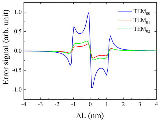
Figure 2.
The simulation results of error signals for three different transverse cavity modes. By misaligning the mirror M1 in Figure 1 by rad and moving the mirror M1 along the optical axis, three different transverse cavity modes can be observed. The blue, red, and green curves correspond to the error signals of , and modes, respectively.
4. Experimental Setup
In general, a high-finesse FP cavity is used to lock a dye laser, and therefore to get a narrow linewidth laser source, but not the reverse. The main reason is that it is difficult to lock two spatially separated high-finesse cavities resonating simultaneously. Nevertheless, the dye laser has the advantage of broad wavelength tuning range, which is usually not reachable by other narrow-band laser sources such as semiconductor diode lasers. In some specific cases, one may need to lock a cavity to resonate at a specific wavelength, which may not be easily available from other laser sources. For example, the rare-earth ions play an important role in quantum storage, and the operating wavelength is determined by the transitions between the energy levels of the rare-earth ions, which may locate in the visible spectral range. One such a typical example is the electromagnetically induced transparency effect (EIT) in -doped crystal, which has many potential applications in quantum storage and quantum repeater. The operating wavelength is at 605.78 nm determined by the hyperfine energy-level transitions of Pr ions. In this case, it is necessary and very convenient to utilize the dye laser as the narrow-band light source.
Figure 3 shows our experimental setup. The laser we used was a Matisse 2 DX dye laser (Spectra-Physics), and the wavelength was tuned to 605.78 nm. The linewidth of the output laser was about 100 kHz. Firstly, the laser beam passed through an electro-optic phase modulator (PM-C-BB, LINOS), which was driven by a function generator with a frequency of 5 MHz. Then it was launched into a home-made FP cavity that consists of a plane mirror M1 and a concave mirror M2, as shown in Figure 1. All these two mirrors were mounted on the invar cavity to isolate vibrations and to minimize the thermal-induced expansion/contraction. A specially designed tiny motorized pitch and yaw platform with a temperature-controlled unit was installed between the two mirrors, which could used to hold the crystal for OPO or other experiments. It ensures that the phase-matching condition can be achieved by tilting the crystal slightly. In Figure 1, we marked each side of mirrors M1 and M2 with a letter. The side a of M1 was coated with antireflection coating for 302.89 nm and 605.78 nm laser light. Both the side b of M1 and the side c of M2 were coated with antireflection coating for 302.89 nm light but highly reflection coating for 605.78 nm light, respectively. The side d of M2 was coated with antireflection coating for both 302.89 nm light and 605.78 nm light. We measured the finesse at 605.78 nm employing the cavity ringdown spectroscopy [31,32]. An accousto-optical modulator AOM (MT110-A1.5-VIS, AA Opto Electronic) was used to switch the input light on and off. Figure 4 shows the ringdown decay dynamics with a decay time constant of 420 ns. The measured finesse F of the FP cavity was 7330, corresponding to a reflection coefficient of . The optical losses of the mirrors were estimated to be about 270 ppm.
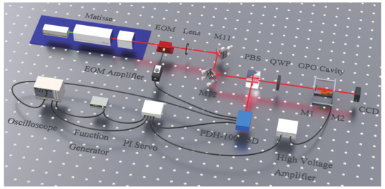
Figure 3.
The experimental setup of locking an FP cavity. The red lines show the direction of laser beams, and the black lines denote the BNC cable. The Matisse 2 DX dye laser was pumped by a Millennia eV 10 W (a diode-pumped solid-state laser from Spectra-Physics), and finely tuned to the frequency 494892 GHz. EOM was an electro-optic phase modulator. Lens was used for mode-matching. M11 and M12 were two mirrors to change the direction and position of the incident laser light. PBS: polarization beam splitter. QWP: quarter-wave plate. The FP cavity was formed by three parts, a plane mirror M1, a temperature-controlled platform, and a concave mirror M2 with a PZT on its back side. CCD: charge coupled device. PDH-1000-5D is an apparatus which integrates photon detector and frequency mixer. PI servo: high-speed proportion integration differentiation controller.
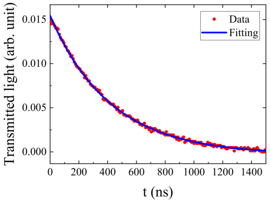
Figure 4.
The ringdown decay dynamics recorded by an oscilloscope. The red dots are experimental results, and the blue curve is the exponential fitting result. The ringdown decay time constant was measured to be 420 ns.
A ring-shaped piezoelectric transducer with a travel distance of was mounted on the side d of mirror M2 to adjust the cavity length. The cavity length L was set to be 54 mm. The free spectral range and the linewidth of the FP cavity can be calculated using Equations (3) and (4), respectively.
where is the refractive index of air. For the experimental parameters in our case, the free spectral range and the linewidth were calculated to be 2.78 GHz and 379 kHz, respectively.
The reflection beam from the FP cavity was selected and fed into a photo-detector (Hamamatsu S5821) using a quarter-wave plate (QWP) and a polarization beam splitter (PBS), which formed an opto-isolator. The photo-detector was a part of the stable laser system PDH-1000-5D (Stable Laser Systems), which also included a function generator (sine wave with a frequency of 5 MHz) and a frequency mixer. Both the electric signals from the photo-detector and the function generator were fed into the frequency mixer, and the product of the two was the error signal. The error signal was fed into a high-speed servo controller (LB1005, Newport). By choosing a proper PI Corner and Gain, one can get the feedback signal that was amplified by 60 times with a low noise through the High Voltage Amplifier (Waviclelaser), and then the feedback signal was loaded onto the ring-shaped piezoelectric transducer to form a closed loop.
5. Experimental Results
The proposed method was experimentally confirmed in an empty FP cavity and a FP cavity with a BBO crystal inside. Here, we first demonstrated the performance of the FP cavity locked to 605.78-nm laser light in a fundamental mode. When applied with a triangle-wave voltage of a frequency 10 Hz (see Figure 5a) to the ring piezoelectric transducer, the corresponding reflection signal and the error signal are shown in Figure 5b,c, respectively. The inset of Figure 5c shows the details of the error signal, which matches well with the fast modulation mode. Note that the error signal is slightly asymmetric. One possible reason is that when scanning a high-finesse FP cavity, the ringing effects will cause the asymmetry of response profile of transmission or reflection light [33,34], as also shown in the inset of Figure 5b. It will destroy the phase information making the error signal asymmetric especially when the modulation frequency of EOM is small. The fundamental mode is widely used in cavity locking experiments for the advantage of high light transmission efficiency and easy alignment. Figure 6 shows the typical error signal when locking the empty FP cavity to a fundamental mode, and the intensity distribution of the transmission beam is shown in Figure 7a. When the FP cavity was locked to the mode at 605.78 nm, all electrical signals fluctuated within a small range. The final linewidth of the cavity was determined by the accuracy of the feedback loop. The stable locking time of the FP cavity is mainly determined by the stability of the reference laser, and a 20-min stable operation was experimentally achieved, which can be easily improved when a more stable reference laser is used.
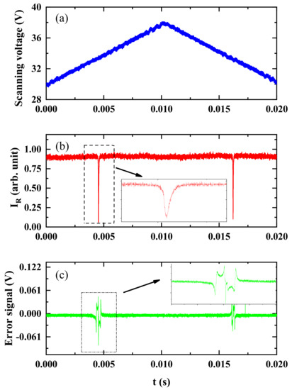
Figure 5.
The scanning voltage (a), the reflection signal (b) and the error signal (c) of the FP cavity when the voltage applied on PZT on mirror M2 is scanning. The insets in (b,c) show the asymmetry of the reflection profile and the details of the error signal, respectively.
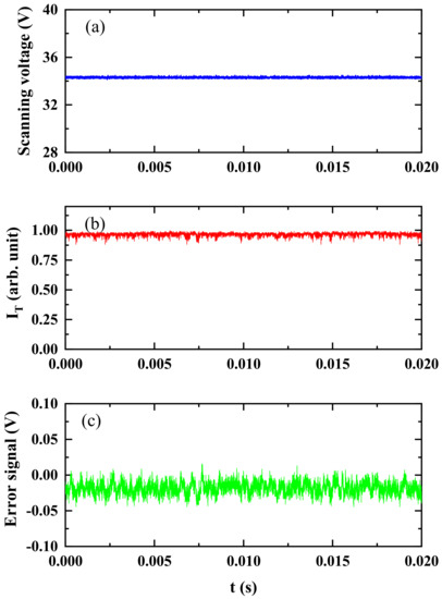
Figure 6.
The output signals from the FP cavity when it is locked to the mode of the dye laser at 605.78 nm. (a) corresponds to the scanning voltage, (b) shows the transmission intensity , and (c) is the error signal.
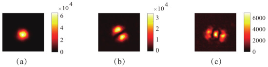
Figure 7.
The intensity distributions of different transverse mode output from the locked FP cavity. (a) is the case with the mode, (b,c) denote the cases with the and modes, respectively.
We also demonstrated the feasibility to lock the FP cavity in the high-order transverse modes. Figure 7b,c show the intensity distribution of the and modes output from the locked FP cavity, while Figure 8 depicts the corresponding error signals from the FP cavity in the , and modes, respectively. The error signals operating in the high-order transverse modes are broader than that in the fundamental mode, and the amplitude of the error signal operating in the high-order transverse modes is smaller than that in the fundamental mode, which makes the cavity more sensitive to the environmental fluctuations/vibrations and difficult to be locked in the high-order transverse modes. The key to improve the stability of the FP cavity operating in the high-order transverse mode is to isolate the vibration in the clean room and employ a stable reference laser. The output signals of the cavity, when locking in and modes, were much like those in Figure 6 (not shown here).
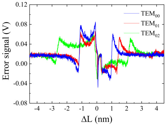
Figure 8.
The error signals output from the FP cavity operating at the (blue curve), the (red curve), and the (green curve) modes, respectively.
For cavity-enhanced SPDC experiments, a nonlinear crystal should be put inside the cavity. The nonlinear crystal is usually birefringent, so one should choose appropriate pump polarization and align the cavity to satisfy the phase-matching condition. Nevertheless, the locking process remains the same.
6. Conclusions
In summary, we successfully locked a high-fineness near-unstable FP cavity to a dye laser in mode by using the PDH stabilization technique. The FP cavity had a linewidth of 379 kHz. This technique linked the FP cavity to the laser cavity, and the frequency of the FP cavity was locked in not only the fundamental transverse mode but also the high-order transverse modes. Such cavity-locked high-order transverse modes are potentially useful in cavity-enhanced SPDC to generate specific transverse modes of single photon and enhance the photon down-conversion efficiency in a specific angle. The design of this plane-concave FP cavity can also increase the threshold of the OPO cavity, which is crucial for single-photon generation. Furthermore, the operating wavelength of our cavity (605.78 nm) is suitable for the EIT experiments in doped crystal, which can be used for single-photon storage and quantum repeater in doped crystal.
Author Contributions
G.Z. supervised the project; J.L. (Jianji Liu) and J.L. (Jiachen Liu) performed the experiments; J.L. (Jianji Liu), J.L. (Jiachen Liu), Z.L. and P.Y. analyzed the data; G.Z. and J.L. (Jianji Liu) wrote the paper; All authors contributed to the discussions and revisions of the paper.
Funding
This work is financially supported by the National Natural Science Foundation of China (Grant Nos. 91750204, 61475077 and 11774182), the 111 project (B07013) and the Fundamental Research Funds for the Central Universities.
Conflicts of Interest
The authors declare no conflict of interest.
Abbreviations
The following abbreviations are used in this manuscript:
| FP | Fabry–Perot |
| SPDC | spontaneous parametric down-conversion |
| BBO | Beta-Barium Borate |
| KDP | Potassium Dihydrogen Phosphate |
| OPO | optical parametric oscillator |
| PDH | Pound-Drever-Hall |
| EOM | electro-optic phase modulator |
| EIT | electromagnetically induced transparency |
| QWP | quarter-wave plate |
| PBS | polarization beam splitter |
References
- Seri, A.; Lenhard, A.; Rielnder, D.; Gndoan, M.; Ledingham, P.M.; Mazzera, M.; de Riedmatten, H. Quantum correlations between single telecom photons and a multimode on-demand solid-state quantum memory. Phys. Rev. X 2017, 7, 021028. [Google Scholar]
- Ou, Z.Y.; Lu, Y.J. Cavity enhanced spontaneous parametric down-conversion for the prolongation of correlation time between conjugate photons. Phys. Rev. Lett. 1999, 83, 2556–2559. [Google Scholar]
- Lu, Y.J.; Ou, Z.Y. Optical parametric oscillator far below threshold: Experiment versus theory. Phys. Rev. A 2000, 62, 033804. [Google Scholar]
- Bao, X.H.; Qian, Y.; Yang, J.; Zhang, H.; Chen, Z.; Yang, T.; Pan, J. Generation of narrow-band polarization-entangled photon pairs for atomic quantum memories. Phys. Rev. Lett. 2008, 101, 190501. [Google Scholar]
- Zavatta, A.; Parigi, V.; Bellini, M. Toward quantum frequency combs: Boosting the generation of highly nonclassical light states by cavity-enhanced parametric down-conversion at high repetition rates. Phys. Rev. A 2008, 78, 033809. [Google Scholar]
- Krischek, R.; Wieczorek, W.; Ozawa, A.; Kiesel, N.; Michelberger, P.; Udem, T.; Weinfurter, H. Ultraviolet enhancement cavity for ultrafast nonlinear optics and high-rate multiphoton entanglement experiments. Nat. Photonics 2010, 4, 170–173. [Google Scholar]
- Fekete, J.; Rielander, D.; Cristiani, M.; de Riedmatten, H. Ultranarrow-band photon-pair source compatible with solid state quantum memories and telecommunication networks. Phys. Rev. Lett. 2013, 110, 220502. [Google Scholar]
- Tian, L.; Li, S.; Yuan, H.; Wang, H. Generation of narrow-band polarization-entangled photon pairs at a rubidium d1 line. J. Phys. Soc. Jpn. 2016, 85, 124403. [Google Scholar]
- Wolfgramm, F.; de Icaza Astiz, Y.; Beduini, F.; Cere, A.; Mitchell, M. Atom-resonant heralded single photons by interaction-free measurement. Phys. Rev. Lett. 2011, 106, 053602. [Google Scholar]
- Rambach, M.; Nikolova, A.; Weinhold, T.; White, A. Sub-megahertz linewidth single photon source. APL Photon. 2016, 1, 096101. [Google Scholar]
- Wang, F.-Y.; Shi, B.-S.; Zhai, C.; Guo, G.-C. Experimental measuring of the coherence length of a single photon generated via a degenerated optical parametric oscillator far below threshold. J. Mod. Opt. 2010, 57, 330–333. [Google Scholar]
- Oberparleiter, M.; Weinfurter, H. Cavity-enhanced generation of polarization-entangled photon pairs. Opt. Commun. 2000, 183, 133–137. [Google Scholar]
- Tanzilli, S.; De Riedmatten, H.; Tittel, W.; Zbinden, H.; Baldi, P.; De Micheli, M.; Ostrowsky, D.; Gisin, N. Highly efficient photon-pair source using periodically poled lithium niobate waveguide. Electron. Lett. 2001, 37, 26–28. [Google Scholar]
- Scholz, M.; Koch, L.; Benson, O. Statistics of narrow-band single photons for quantum memories generated by ultrabright cavity-enhanced parametric down-conversion. Phys. Rev. Lett. 2009, 102, 063603. [Google Scholar]
- Haase, A.; Piro, N.; Eschner, J.; Mitchell, M. Tunable narrowband entangled photon pair source for resonant single-photon single-atom interaction. Opt. Lett. 2009, 34, 55–57. [Google Scholar]
- Zhang, H.; Jin, X.-M.; Yang, J.; Dai, H.-N.; Yang, S.-J.; Zhao, T.-M.; Rui, J.; He, Y.; Jiang, X.; Yang, F.; et al. Preparation and storage of frequency-uncorrelated entangled photons from cavity-enhanced spontaneous parametric downconversion. Nat. Photonics 2011, 5, 628–632. [Google Scholar]
- Wang, H.; Dovale-Alvarez, M.; Collins, C.; Brown, D.; Wang, M.; Mow-Lowry, C.; Han, S.; Freise, A. Feasibility of near-unstable cavities for future gravitational wave detectors. Phys. Rev. D 2018, 97, 022001. [Google Scholar]
- Tu, Y.; Zhang, G.; Zhai, Z.; Xu, J. Angular multiplexing storage of light pulses and addressable optical buffer memory in Pr3+:Y2SiO5 based on electromagnetically induced transparency. Phys. Rev. A 2009, 80, 033816. [Google Scholar]
- Fleischhauer, M.; Imamoglu, A.; Marangos, J. Electromagnetically induced transparency: Optics in coherent media. Rev. Mod. Phys. 2005, 77, 633–673. [Google Scholar]
- Kogelnik, H.; Li, T. Laser beams and resonators. Proc. IEEE 1966, 54, 1312–1329. [Google Scholar]
- Hamilton, M.W. An introduction to stabilized lasers. Contemp. Phys. 1989, 30, 21–33. [Google Scholar]
- Drever, R.; Hall, J.; Kowalski, F.; Hough, J.; Ford, G.; Munley, A.; Ward, H. Laser phase and frequency stabilization using an optical resonator. Appl. Phys. B 1983, 31, 97–105. [Google Scholar]
- Black, E. An introduction to pound drever hall laser frequency stabilization. Am. J. Phys. 2001, 69, 79–87. [Google Scholar]
- Hansch, T.; Couillaud, B. Laser frequency stabilization by polarization spectroscopy of a reflecting reference cavity. Opt. Commun. 1980, 35, 441–444. [Google Scholar]
- You, Y.; Chiche, R.; Yan, L.; Huang, W.; Tang, C.; Zomer, F. High finesse pulsed optical cavity locking by tilt-locking technique. Rev. Sci. Instrum. 2014, 85, 033102. [Google Scholar]
- Slagmolen, B.; Shaddock, D.; Gray, M.; McClelland, D. Frequency stability of spatial mode interference (tilt) locking. IEEE J. Quantum Electron. 2002, 38, 1521–1528. [Google Scholar]
- Bond, C.; Fulda, P.; Carbone, L.; Kokeyama, K.; Freise, A. Higher order laguerre-gauss mode degeneracy in realistic, high-finesse cavities. Phys. Rev. D 2011, 84, 102002. [Google Scholar]
- Carbone, L.; Bogan, C.; Fulda, P.; Freise, A.; Willke, B. Generation of high-purity higher-order laguerre-gauss beams at high laser power. Phys. Rev. Lett. 2013, 110, 251101. [Google Scholar]
- Chelkowski, S.; Hild, S.; Freise, A. Prospects of higher-order laguerre-gauss modes in future gravitational wave detectors. Phys. Rev. D 2009, 79, 122002. [Google Scholar]
- Fulda, P.; Kokeyama, K.; Chelkowski, S.; Freise, A. Experimental demonstration of higher-order laguerre-gauss mode interferometry. Phys. Rev. D 2010, 82, 012002. [Google Scholar]
- Anderson, D.; Frisch, J.; Masser, C. Mirror reflectometer based on optical cavity decay time. Appl. Opt. 1984, 23, 1238–1245. [Google Scholar]
- Paldus, B.; Harb, C.; Spence, T.; Wilke, B.; Xie, J.; Harris, J.; Zare, R. Cavity-locked ring-down spectroscopy. J. Appl. Phys. 1998, 83, 3991–3997. [Google Scholar]
- Poirson, J.; Bretenaker, F.; Vallet, M.; le Floch, A. Analytical and experimental study of ringing effects in a Fabry–Perot cavity. Application to the measurement of high-finesses. JOSA B 1997, 14, 2811–2817. [Google Scholar]
- Rohde, H.; Eschner, J.; Schmidt-Kaler, F.; Blatt, R. Optical decay from a Fabry–Perot cavity faster than the decay time. JOSA B 2002, 19, 1425–1429. [Google Scholar]


© 2019 by the authors. Licensee MDPI, Basel, Switzerland. This article is an open access article distributed under the terms and conditions of the Creative Commons Attribution (CC BY) license (http://creativecommons.org/licenses/by/4.0/).