Article

An Improved Method for Predicting the Greenfield Stratum Movements Caused by Shield Tunnel Construction

1
China Railway Eryuan Engineering Croup Co. LTD, Chengdu 610031, China
2
Key Laboratory of Transportation Tunnel Engineering, Ministry of Education, Southwest Jiaotong University, Chengdu 610031, China
3
Department of Road and Bridge Engineering, Sichuan Vocational and Technical College of Communications, Chengdu 611130, China
*
Authors to whom correspondence should be addressed.
Appl. Sci. 2019, 9(21), 4522; https://doi.org/10.3390/app9214522
Submission received: 23 September 2019 / Revised: 21 October 2019 / Accepted: 21 October 2019 / Published: 24 October 2019

Abstract

:
Shield tunneling is becoming the preferred construction scheme for metro construction because of its advantages of fast construction speed and small disturbance. However, limited by process defects, the stratum movements induced by the construction of shield tunnels still affects the safety of nearby underground structures and aboveground buildings. Therefore, the reliable prediction of stratum movements is important. Described in this paper is an analysis method of the Greenfield stratum movements (Greenfield is an area of land that has not yet had buildings on it, stratum movements means the movement of various soil layers) caused by shield tunnel construction combining an elastic half-space model of mirror source–sink method with the use of modified analytical method. Based on the theoretical formula in this paper, not only can the curve of surface settlement trough be calculated, but also the three-dimensional displacement field of deep soil can be obtained. By comparing vertical and horizontal contour maps of Greenfield stratum movements, good consistency between theoretical formula results and centrifugal test results are shown. This solves the defects and limitations of existing two-dimensional formulas; furthermore, based on this, it is convenient to evaluate the effect on the other skewed underground structures through the elastic foundation beam and other similar methods; therefore, this paper can provide a wide guidance and service for the design and construction of underground engineering in the future.

1. Introduction

Since the 21st century, tunnel and underground engineering in China have made great progress [1,2,3,4,5,6,7]. With the continuous development of urbanization in China, the urban population is growing, and urban traffic pressure is also increasing. In order to alleviate the urban traffic pressure, city managers have taken a lot of measures, such as limited number driving, expansion, and transformation of existing roads, but the traffic demand is still far greater than the current urban ground carrying capacity. Metro has the advantages of large passenger capacity, fast speed, and full use of underground space, which is more and more popular in modern society. However, the urban subway has strict requirements for its construction methods. Because of the high density of buildings in cities, the construction of the metro will cause stratum movement and bring adverse effects on ground buildings. Especially when passing through high-rise buildings, the disturbance caused by construction on stratum must be more strictly controlled. The construction period of Metro is long, and the interruption of traffic should be avoided as far as possible when crossing the road. Usually, subway construction methods include the open-cut method, shallow-buried excavation method, and shield tunneling method. Among them, the shield tunneling method has become the preferred construction scheme for metro construction because of its great advantages of fast construction speed, a high degree of automation, and small disturbance to stratum [8,9].
Although shield tunneling has many advantages mentioned above, and the construction technology has made great progress after many years of development, due to the defects of geological conditions and construction technology, the advance of shield tunneling will inevitably make a disturbance, change the stress state of soil, and cause stratum displacement, as shown in Figure 1. If the disturbance of stratum cannot be clearly understood, it will affect the safety of nearby underground structures and aboveground buildings. For example, the adjacent metro tunnels may cause deformation restrictions beyond the normal operation of the metro, or even lead to train derailment; it may also lead to the breakage of underground pipelines, resulting in a series of problems, such as gas leakage, interruption of urban water use, interruption of communication power system, and so on, affecting the daily life of the city [10,11,12]. Therefore, a reliable prediction of stratum movements is important.
Over the years, previous researchers have done numerous studies on the effects of shield tunnel construction on stratum displacement [13,14,15,16,17,18]. In the direction of theoretical research, Peck assumed that the curve of land settlement trough satisfies the conditions of Gauss distribution and invariant stratum volume, and deduced Peck’s empirical formula based on many field monitoring data [19]. Attewell et al. used Peck’s empirical formula to simulate the free displacement of soil at the location of existing tunnels [20,21,22,23,24], and then deduced the displacement of existing tunnels with elastic foundation beams and other models. However, Celestino and Klar [25,26] gradually found that the Peck curve could not accurately describe soil settlement trough in many cases. Voster, O’Reilly et al. [27,28,29,30] have proposed fitting curves from different research angles to fit the free displacement field of soils. Litwinszyn [31] put forward the theory of random medium through a sand box test. Liu, Yang, et al. [32,33,34] introduced this theory into the prediction of stratum displacement caused by the excavation of geotechnical tunnels. Although these studies have the advantages of concise calculation formula and convenient use, they lack a clear theoretical basis of mechanics. They can only be called a mathematical empirical method, not an analytical solution of soil settlement. Because the empirical formula is fitted by a large number of field monitoring data, the parameters of the fitting function are closely related to the actual construction conditions, and lack of a clear theoretical basis, the accuracy of the results predicted by this method is often difficult to meet the requirements, and its defects are evident. Comparatively, the solving process of the analytic method and modified analytic method is relatively complex, but through more rigorous analysis, as long as the parameters are selected properly, it has better universality. Sagaseta [35] deduced the expression of three-dimensional displacement of stratum by using the mirror source–sink method. This formula can not only calculate the curve of surface settlement trough, but also calculate the displacement and stress of deep soil, so it is widely used [36,37,38,39,40,41,42,43]. However, the movement pattern of actual volume loss is not consistent with the assumed equivalent radial movement pattern in this method and has some deviation. Based on field monitoring data, Loganathan, Jiang, and other researchers [44,45,46,47,48,49,50,51] modified the stratum displacement pattern by exponential function and deduced the prediction formula of surface subsidence under non-equivalent radial movement pattern. However, most of these methods are only suitable for three-dimensional orthogonal plane or two-dimensional cases, which have great defects and need to be improved urgently. Many other researchers concerned the field description, soil classification for engineering purposes [52,53,54], and the analysis methods of data such as neural networks [55,56,57,58]. Saplachidi et al. [59] used measured settlements from the tunneling excavation for the extension of Line 3 of the Athens Metro for the verification and calibration of the empirical formulae. Suwansawat et al. [60] evaluated the potential and the limitations of artificial neural networks (ANN) for predicting surface settlements caused by Earth pressure balance (EPB) shield tunneling and to develop optimal neural network models for this objective. Ahangari et al. [61] created a database from previous research [62,63,64,65] and studied the capability of adaptive neuro-fuzzy inference system (ANFIS) and gene expression programming (GEP) methods for settlement prediction. However, those methods belong to the fuzzy solutions without mechanism analysis, training neural networks requires a lot of data from databases or numerical simulation, and there are problems such as difficult convergence or slow convergence speed.
This paper studies the Greenfield stratum movements caused by shield tunnel construction combining an elastic half-space model of mirror source–sink method with the use of modified analytical method. Through theoretical derivation and empirical function modification, the prediction formula of three-dimensional Greenfield stratum movements is improved, and it shows good consistency with the centrifugal test results. The new solution can calculate the three-dimensional stratum displacement accurately, which is unavailable for the previous methods. It can be used in the process of tunnel excavation rather than only for the ultimate settlement. Based on this improved solution, it is convenient to evaluate the effect on the other skewed underground structures through the elastic foundation beam and other similar methods; therefore, this paper can provide a wide guidance and service for the design and construction of underground engineering in the future.

2. Basic Theory and Calculation Method

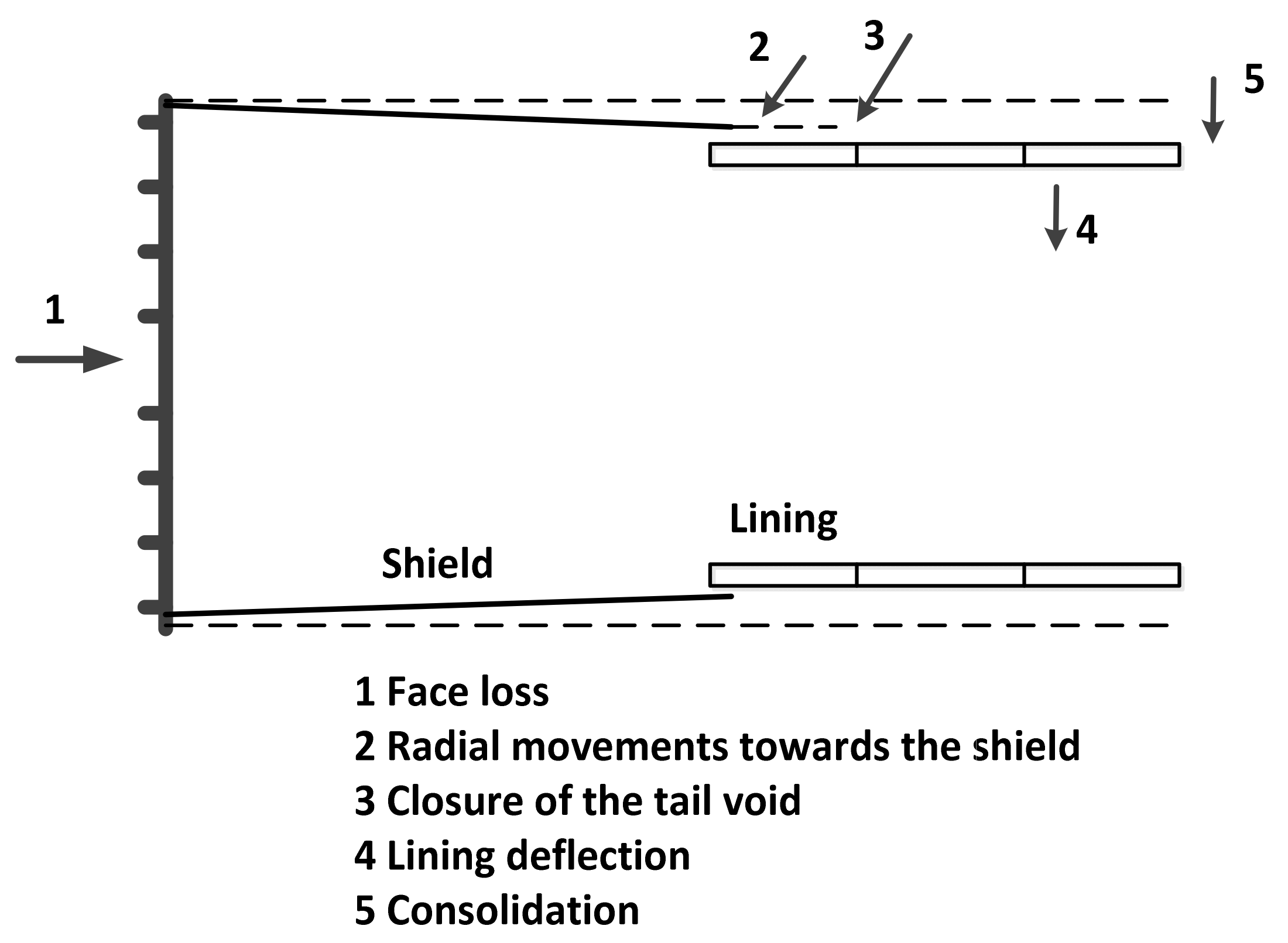
2.1. Disturbance Factors

Usually, there are three factors that cause disturbance of surrounding soil by shield tunneling technology: First, the gap between segment lining and stratum due to the reasons of assembling segment lining, shield overcutting, shield snake-shaped, and shield body adjustment; although synchronous grouting is adopted, the grouting cannot completely eliminate the gap at present [66]; the second is the elastic-plastic deformation of the soil at the shield heading face, which is closely related to the soil characteristics and the additional force on the shield working face. Thirdly is the horizontal friction between the outer surface of the shield and the surrounding soil. Compared with the effect of the gap, the stratum movements caused by the additional force on the shield working face and the frictional force between the outer surface of the shield and the surrounding soil during tunnel construction is very small [67]. Therefore, this paper neglects the effects of the latter two factors when analyzing, and mainly studies the effects of the gap. Sources of stratum movements of shield tunnel are shown in Figure 1 and the coordinate system is set as shown in Figure 2 [68].

2.2. Gap Parameter

In order to analyze the effects of the above factors, Rowe et al. [69,70] proposed the concept of gap parameter to reflect the stratum loss caused by shield tunnel construction, transforming the three-dimensional problem to a two-dimensional gap in plane. The composition of the gap takes into account the following factors: Elastic-plastic deformation of the shield at the tunnel excavation face, the over-excavation of the shield machine, the physical gap between the outer skin of shield shell and segment lining, and the construction technology. The formula for calculating the gap parameters g under undrained condition is as in Equation (1).
g = G P + U 3 D * + ω
where shows that the gap parameters are composed of three parts [44]:
The first part Gp is the physical gap, which represents the gap between the outer skin of shield shell and segment lining; its expression is as in Equation (2):
G P = 2 Δ + δ
where Δ is the thickness of shield shell and δ is the space formed by segment lining installation.
The second part U3D is the elastic-plastic deformation of shield at the tunnel excavation face; its quantitative expressions are as in Equations (3) and (4):
U 3 D = k 2 δ y = k 2 Ω R P 0 E
P 0 = K 0 P v + P w P f
where k is the soil cutting resistance coefficient; Ω is the displacement coefficient; R is the tunnel radius; E is the elastic modulus; K’0 is the effective static lateral pressure coefficient; P’v is the effective vertical stress at depth of tunnel center; Pw is the pore water pressure at depth of tunnel center; and Pf is the supporting force provided by tunnel.
The third part ω is the shield construction technology coefficient, of which the value is as in Equation (5):
{ U i R = 1 ( 1 1 + 2 ( 1 + μ u ) C u E u [ e x p ( N 1 2 ) ] 2 ) 1 2 N = γ H p f C u ω = m i n { 0.6 G p ,   1 3 U i }
where Ui is the elastoplastic plane strain displacement at the tunnel crown; μu is the soil Poisson’s ratio under undrained condition; Cu is the soil shear strength under undrained condition; Eu is the soil elastic modulus under undrained condition; γ is the unit weight of soil; and H is the buried depth of tunnel center.

2.3. Loganathan’ Solution

Based on the above formulas, Loganathan proposed to use plane loss rate εx,z to quantify stratum loss with non-equivalent radial movement. The expression is as in Equation (6):
ε x , z = 4 g R + g 2 4 R 2 exp { | 1.38 x 2 ( H + R ) 2 + 0.69 z 2 H 2 | } .
Combined with Verruijit’s [71,72] analytical formula, he put forward a formula for estimating stratum displacement caused by undrained stratum loss in clays, of which the formulas are as in Equation (7):
{ S z = R 2 { z H x 2 + ( z H ) 2 + ( 3 4 μ ) z + H x 2 + ( z + H ) 2 2 z [ x 2 ( z + H ) 2 ] [ x 2 + ( z + H ) 2 ] 2 } × ε x , z S x = R 2 x { 1 x 2 + ( z H ) 2 + ( 3 4 μ u ) x 2 + ( z + H ) 2 4 z ( z + H ) [ x 2 + ( z + H ) 2 ] 2 } × ε x , z .
Considering that the displacement solution caused by stratum loss derived by Loganathan is a two-dimensional solution, which is often a three-dimensional problem in actual engineering, it is necessary to extend the two-dimensional displacement solution to three-dimensional. In the above deduction process, we can find that the stratum loss parameter εx,z is the key for extending. If we extend the plane stratum loss parameter εx,z to three-dimensional parameter εx,z,y, the displacement solution can be extended to three-dimensional space. Another important method to solve the stratum displacement caused by stratum loss is used here. The concept of stratum loss proposed by Sagaseta proposed the mirror source–sink method and derives the problem of free displacement field by elastic half-space model. Although field monitoring data [40] show that the movement pattern of actual volume loss is not consistent with the assumed equivalent radial movement pattern in this method, its process is a strict mathematical derivation process, so the three-dimensional stratum loss parameter εx,z,y can be extracted from the Sagaseta solution.

2.4. Sagaseta’s Solution

Sagaseta used the mirror source–sink method, assumed that the surface is free, the soil is isotropic, and incompressible. The analysis steps are as follows and in Figure 3:
First step: The existence of the original surface is ignored, and the half-space problem is transformed into the internal gap problem of full space. Under the action of a source gap, stress field changing, there will be the normal stress σ0 and the shear stress τ0 at the original surface position.
Second step: A sink is set at the mirror position of the source gap above the original surface; there is a volume expansion of the same size at the sink position. The sink expansion will produce a normal stress −σ0 of the same value and opposite direction and a shear stress τ0 of the same value and same direction at the original surface position. Therefore, under the action of source and sink, the normal stress on the original surface can be offset, which does not exist in practice.
Third step: Under the action of source and sink, a shear stress −2τ0 of twice the value and opposite direction is supposed at the original surface position and the corresponding displacement field of the surface shear stress below the surface at each point can be obtained.
Final step: The displacements generated by the above three steps at any point below the surface are S1, S2, and S3, respectively. The displacement solution of the practical problem is S = S1 + S2 + S3.
Based on above steps, Sagaseta deduced the expression of surface displacement caused by tunnel construction is as in Equation (8):
{ S x 0 = v l o s s 2 π x x 2 + H 2 [ 1 + y ( x 2 + y 2 + H 2 ) 1 2 ] S y 0 = v l o s s 2 π 1 ( x 2 + y 2 + H 2 ) 1 2 S z 0 = v l o s s 2 π H x 2 + H 2 [ 1 + y ( x 2 + y 2 + H 2 ) 1 2 ] S x 0 ( y ) = v l o s s π x x 2 + H 2 S z 0 ( y ) = v l o s s π H x 2 + H 2
where Vloss is stratum loss. Contrastive Equation (8) can be found:
{ S x 0 ( y ) = S x 0 ( y ) × 1 2 × [ 1 + y ( x 2 + y 2 + H 2 ) 1 2 ] S z 0 ( y ) = S z 0 ( y ) × 1 2 × [ 1 + y ( x 2 + y 2 + H 2 ) 1 2 ] .

2.5. An Improved Method

Equation (9) shows that the distribution of stratum displacement caused by shield construction (stratum loss) along the y-axis driving satisfies the law of 1 2 × [ 1 + y ( x 2 + y 2 + H 2 ) 1 2 ] . Therefore, based on this law, the Loganathan’s solution is extended to the three-dimensional. It is noticed that the coordinate system adopted in this paper is different from that used in the Sagaseta’s solution, so the distribution law should be revised, and its expression is as in Equation (10):
ε y = 1 2 × [ 1 y ( x 2 + y 2 + H 2 ) 1 2 ] .
The plane stratum loss parameter εx,z is extended to three-dimensional parameter εx,z,y:
ε x , y , x = ε y × ε x , z = [ 1 y ( x 2 + y 2 + H 2 ) 1 2 ] × 4 g R + g 2 8 R 2 exp { | 1.38 x 2 ( H + R ) 2 + 0.69 z 2 H 2 | }
εx,z is replaced by εx,z,y in Equation (7) and Equation (12) is the three-dimensional analytical solution of stratum displacement caused by stratum loss. When y = 0, z = 0, the curves of settlement trough calculated by Equations (7), (8), and (12) are the same, and Equation (8) is the particular solution about the surface settlement value of Equation (12) at the tunnel face.
{ S z = R 2 { z H x 2 + ( z H ) 2 + ( 3 4 μ ) z + H x 2 + ( z + H ) 2 2 z [ x 2 ( z + H ) 2 ] [ x 2 + ( z + H ) 2 ] 2 } × ε x , y , z S x = R 2 x { 1 x 2 + ( z H ) 2 + ( 3 4 μ ) x 2 + ( z + H ) 2 4 z ( z + H ) [ x 2 + ( z + H ) 2 ] 2 } × ε x , y , z
For example, let H = 13.65 m, µ = 0.4, R = 2.325 m, g = 0.058 m, then the displacement of soil layers at z = 0 m and z = 10 m is showed in Figure 4.

3. Compared with Centrifugal Test Results

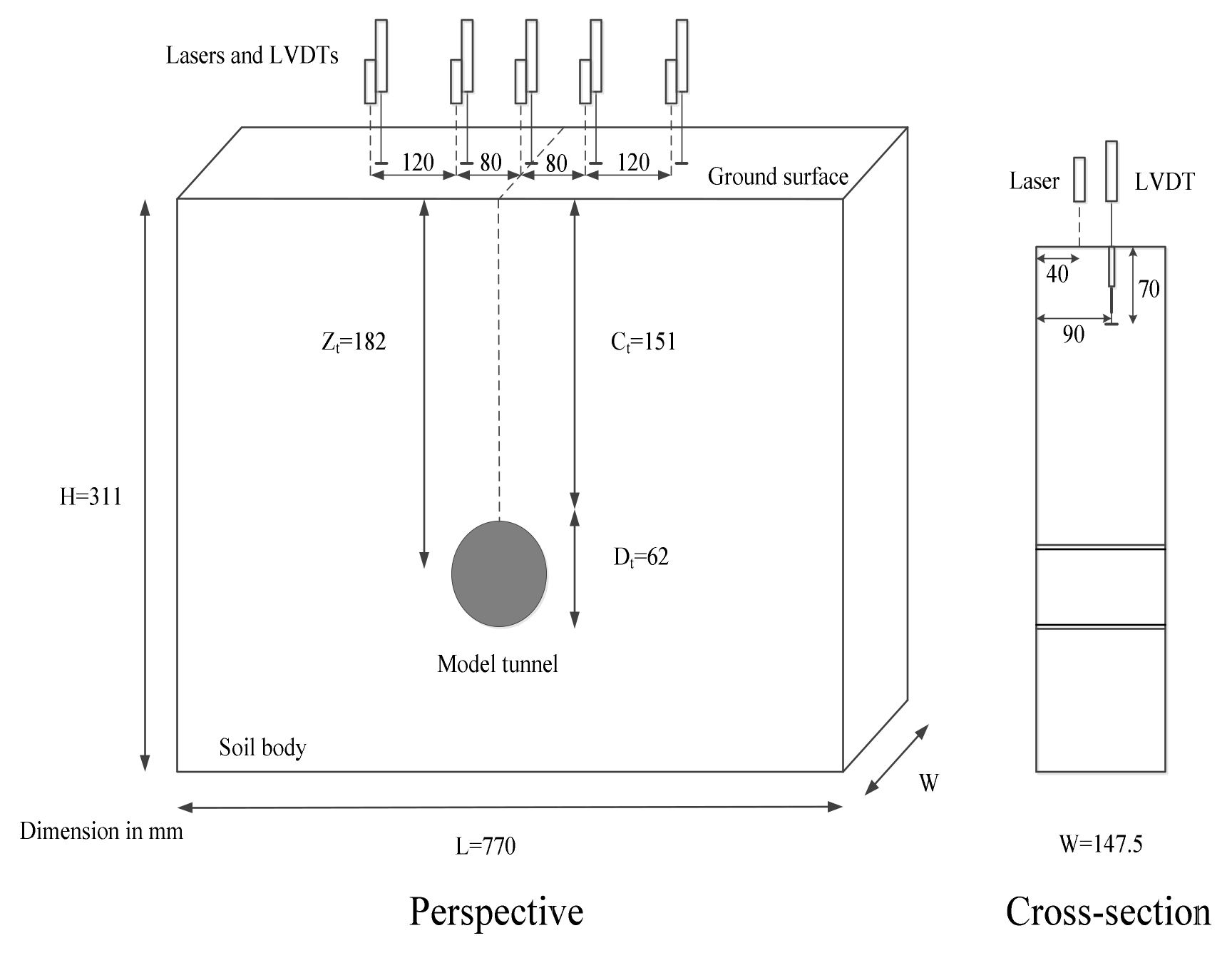
3.1. Material Properties

British scholar Marshall [73] designed a series of model tests to study the influence of shield tunneling in sandy ground by using the geocentrifugal testing machine of Cambridge University. The design conditions and dimensions of centrifuge model test are shown in Figure 5. The bottom dimension of the test box containing model tunnels and sand is 770 mm × 147.5 mm, and the sand depth after filling is 311 mm; the axis depth of the shield tunnel model is Zt = 182 mm, the tunnel diameter is Dt = 62 mm, the section dimension of the model tunnel is shown in Figure 6, and the length of the shield tunneling section is L0 = 147.5 mm.
The test soil samples were taken from dry Leighton Buzzard Fraction E silica sand, UK, and its parameters are shown in Table 1. This sand has a typical D50 of 122 µm [74], a specific gravity of 2.67, and maximum and minimum void ratios of 0.97 and 0.64 [75], respectively. Uniform sand with relative density of 90% was prepared by automatic sand leaker. The elastic modulus E of sand soil is 20 MPa and Poisson’s ratio µ is 0.4. The whole test process was carried out under the centrifugal acceleration of 75× g (g is the acceleration of gravity); namely, the scale ratio of the test size was 75 times. Therefore, this test is equivalent to simulating a shield tunnel with a diameter of 4.65 m (model diameter 62 mm) and a tunnel central burial depth of 13.65 m (model tunnel central burial depth 182 mm) passing through Greenfield in reality. In the process of shield excavation, the simulation of stratum loss is realized by using a cylinder sealed with liquid connected to the tunnel driven by a motor. The stratum loss rate rises at a rate of about 0.3% per minute. The above test parameters are brought into Equation (12) for theoretical calculation of stratum displacement. Considering the clarity and regularity of result image, the test results of medium volume loss of 2.5% are compared.

3.2. Comparative Analysis of Results

The comparative analysis of the results is shown in Figure 7; the vertical displacement contours of 37.5 mm and 30 mm in the central part show good consistency and regularity. In general, the centrifugal test results are nearly straight-line contours, while the theoretical calculation results are arc contours, which also leads to a large difference between 22.5 mm, 15 mm, and 7.5 mm contours, and shows a trend of increasing the difference from the center to the edge.
As for vertical displacement, the numerical value is relatively small, and its regularity is not obvious. This can also be seen from the poor symmetry of the left and right halves of the horizontal displacement in the centrifugal test nephogram. The shape and distribution position of centrifugal contours and theoretical contours are similar, especially the upper 4 mm curve and the central 2 mm curve. However, the difference between theoretical contours and centrifugal contours also shows an increasing trend from the center to the edge, the whole lines shift to the right a little, and the theoretical contour has a wider range. This is consistent with the law that the settlement trough of sand is narrower and deeper than that of clay [76].
Due to sand soil being chosen as the test soil sample in centrifugal test, Sagaseta’s solution is applicable to sand soil, but another important part of our theoretical formula, Loganathan’s solution, is only applicable to clay soil. Be aware of the exponential function of Loganathan’ solution modify the formation loss coefficient by fitting the clay soil data, although the soil parameters substituted in Equation (12) are sand soil’s, which cannot eliminate the difference between the Loganathan’s εx,z and the properties of sand. This leads to the fact that in the vertical displacement contours, the centrifugal contours are linear and the theoretical contours arc, which is similar to the difference between the two on the slip fracture surface of soil. Generally, clay soil has a complex composition, elastic-plastic deformation occurs easily, deformation has a time-delay property, and many other disturbing factors, all of which are very unfavorable to the test analysis. However, sand soil has a single material, of which properties are easier to control in the test, and the drainage or non-drainage conditions need not be considered. Therefore, the current centrifugal tests are mostly based on sand. We regret that we have not found a suitable clay centrifugal test as a reference. However, considering the inevitable errors in centrifugal test and theoretical calculations, the comparison results are still acceptable.

4. Conclusions

(1)
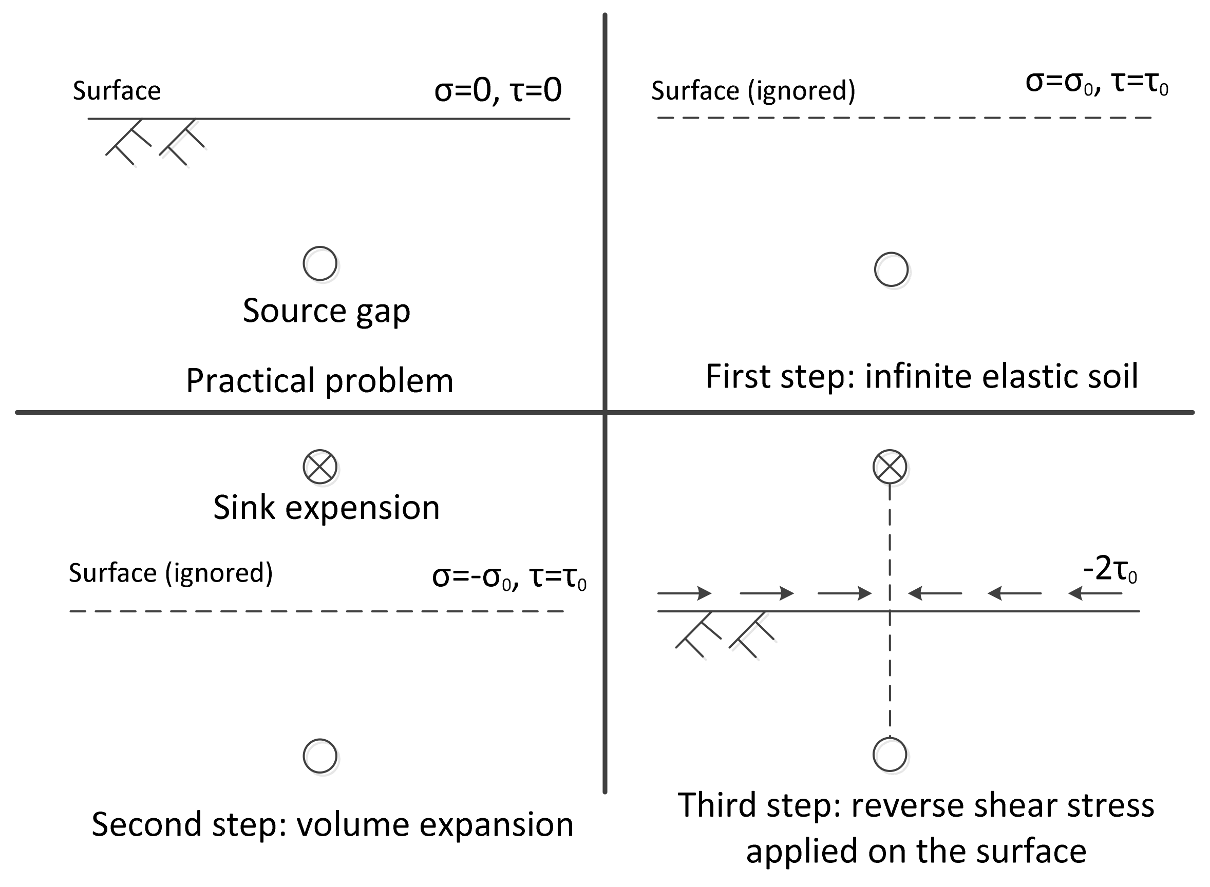
A new method for predicting the stratum movements caused by EPB shield tunnel construction is developed that combines an elastic half-space model of mirror source–sink method with the use of modified analytical method. Compared with the effect of a physical gap, the stratum movements caused by the additional force on the shield working face and the frictional force between the outer surface of the shield and the surrounding soil during tunnel construction is very small. Therefore, this paper neglects the effects of the latter two factors when analyzing, and mainly studies the effects of the physical gap. The method also takes into account non-equivalent radial ground loss.
(2)
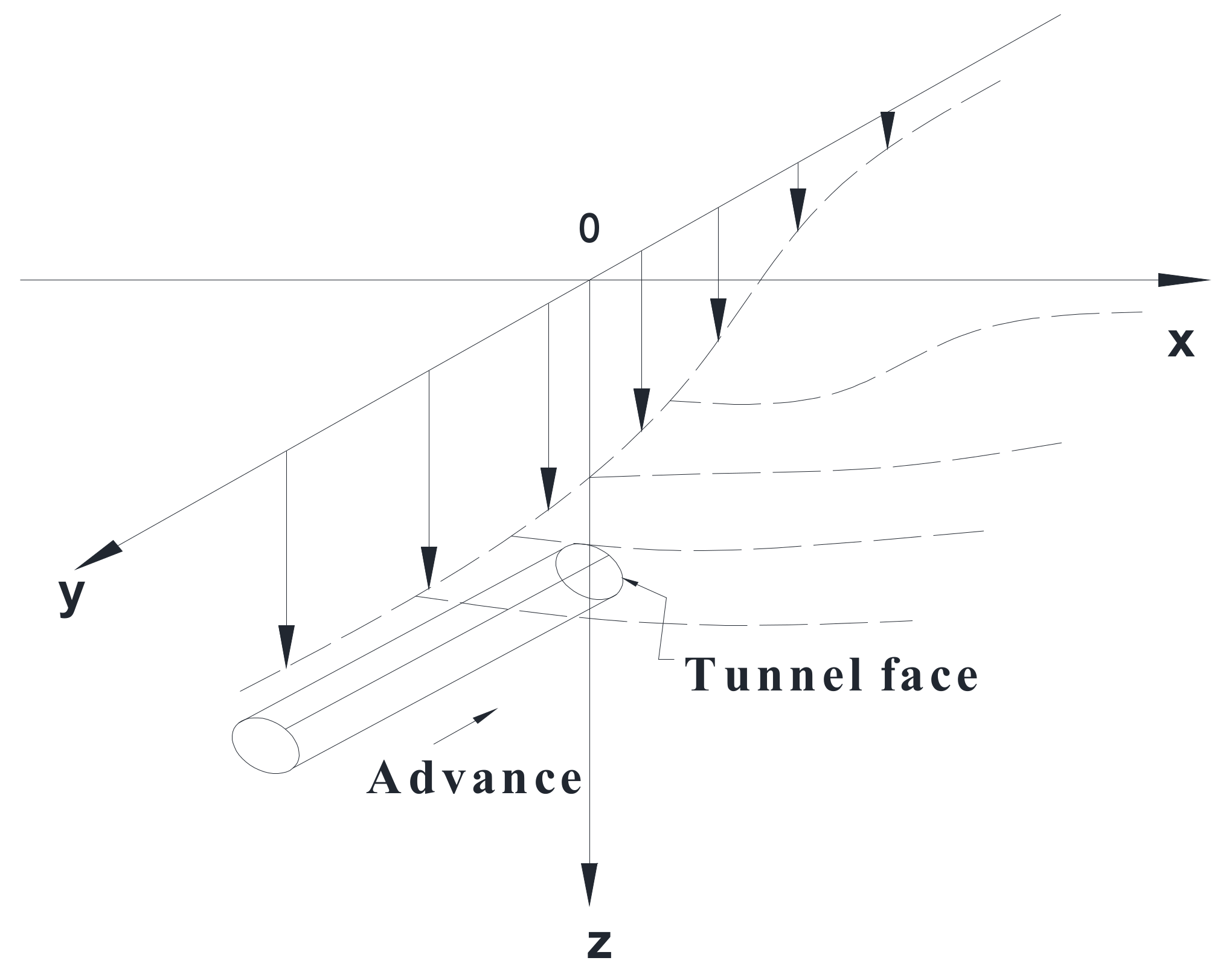
Sagaseta’s method assuming equivalent radial movement pattern can only obtain the surface movements from the tunnel excavation. Considering non-equivalent radial displacement model, Loganathan’s solution modifies Verruijit’s analytical formula by exponential function, but it is only applicable to plane strain cases. The two methods have great limitations. For example, they cannot show the soil displacement of the x = y plane. If there is a new shield tunnel skewed with an old tunnel or pipeline and the displacement effect at the old tunnel or pipeline needs to be calculated, neither of the above two methods will apply. This paper combines the advantages of the two methods to derive a formula for predicting the three-dimensional stratum displacement caused by shield tunneling.
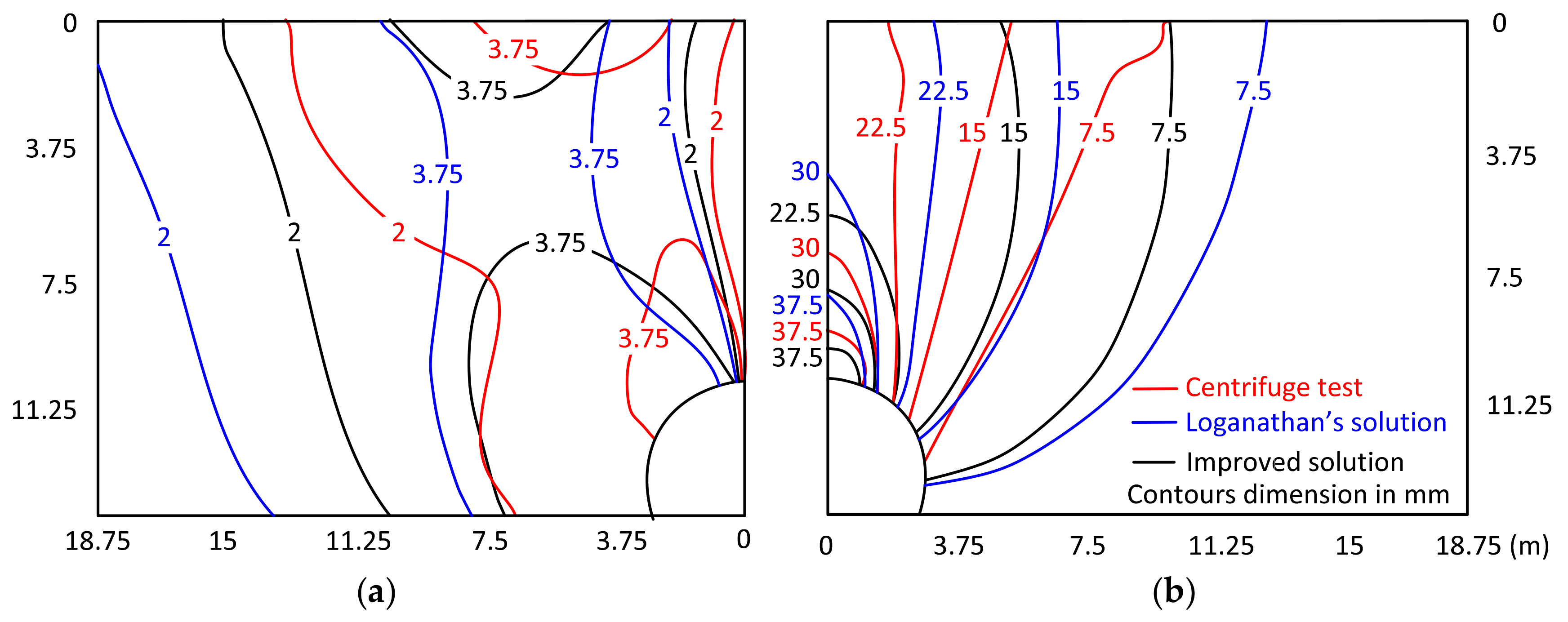
(3)
Vertical displacement contours in the central part show good consistency and regularity, with a larger difference at the edge. Centrifugal contours are nearly straight-line contours, while the improved solution contours are arc. Vertical displacement has a relatively small numerical value and its regularity is not obvious. The shape and distribution position of centrifugal contours and improved contours are similar. The difference also shows an increasing trend from the center to the edge, and the improved solution contours shift to the right a little and has a wider range. One of the important reasons is that sand soil is chosen in the centrifugal test but part of Loganathan’s solution is fitted with clay data and is only applicable to clay soil. The current centrifugal tests are mostly based on sand. However, suitable clay centrifugal tests are hard to find. Considering the inevitable errors in the centrifugal test and theoretical calculations, the comparison results are acceptable. The values of Loganathan’s contours are larger than the other two, because Loganathan’s solution is the plane strain method; namely, it is a final stratum displacement from the excavation of an infinite tunnel. However, in the test and the improved method, the tunnel length is finite, the distance between the measuring plane and the tunnel face is much shorter, so their displacements are smaller than the final displacement.

Author Contributions

X.T. wrote the article; H.Z. carried out the calculations and analyzed the calculation results; G.Z. and Y.Z. processed the data; P.T. offered some useful suggestions for the preparation.

Funding

The study was supported by the National Natural Science Foundation of China (NSFC) under Grant No. 51508037.

Acknowledgments

We also highly appreciate reviewers for useful comments and editors for improving the manuscript.

Conflicts of Interest

The authors declare no conflict of interest.

References

  1. Zhang, H.; Chen, L.; Zhu, Y.; Zhou, Z.; Chen, S. Stress Field Distribution and Deformation Law of Large Deformation Tunnel Excavation in Soft Rock Mass. Appl. Sci. 2019, 9, 865. [Google Scholar] [CrossRef]
  2. Zhang, Z.Q.; Zhang, H.; Tan, Y.J.; Yang, H.Y. Natural wind utilization in the vertical shaft of a super—Long highway tunnel and its energy saving effect. Build. Environ. 2018, 145, 140–152. [Google Scholar] [CrossRef]
  3. Zhu, Y.; Chen, L.; Zhang, H.; Zhou, Z.; Chen, S. Physical and Mechanical Characteristics of Soft Rock Tunnel and the Effect of Excavation on Supporting Structure. Appl. Sci. 2019, 9, 1517. [Google Scholar] [CrossRef]
  4. Zhang, H.; Chen, L.; Chen, S.G.; Sun, J.C.; Yang, J.S. The spatiotemporal distribution law of microseismic events and rockburst characteristics of the deeply buried tunnel group. Energies 2018, 11, 3257. [Google Scholar] [CrossRef]
  5. Tang, F.; Li, L.J.; Dong, M.S.; Wang, Q.; Mei, F.Z.; Hu, L.H. Characterization of buoyant flow stratification behaviors by Richardson (Froude) number in a tunnel fire with complex combination of longitudinal ventilation and ceiling extraction. Appl. Therm. Eng. 2017, 110, 1021–1028. [Google Scholar] [CrossRef]
  6. Mei, F.Z.; Tang, F.; Ling, X.; Yu, J.S. Evolution characteristics of fire smoke layer thickness in a mechanical ventilation tunnel with multiple point extraction. Appl. Therm. Eng. 2017, 111, 248–256. [Google Scholar] [CrossRef]
  7. Sun, J.; Zhang, H.; Huang, M.; Chen, Q.; Chen, S. Reasonable Paths of Construction Ventilation for Large—Scale Underground Cavern Groups in Winter and Summer. Sustainability 2018, 10, 3768. [Google Scholar] [CrossRef]
  8. Lin, F.; Chen, S.G.; Zhang, H. Study on type selection of shield equipment in different geological conditions. In Green Building, Materials and Civil Engineering; CRC Press: Boca Raton, FL, USA, 2014; pp. 391–394. [Google Scholar]
  9. Zhang, H.; Chen, S.G.; Deng, X.F. Analysis on Influence of Shield Tunneling on Ground and Bridge Pile. Chin. J. Undergr. Space Eng. 2011, 7, 552–557. [Google Scholar]
  10. Zhang, H.; Chen, S.G.; Tan, X.R. Research on the Mechanical Behavior of a Segment of a Shield Tunnel Adjacent to a Pile Foundation. Mod. Tunn. Technol. 2012, 49, 101–107. [Google Scholar]
  11. Zhou, Z.L.; Chen, S.G.; Li, Y.S. Research on Predicting and Distribution of Stratum Displacement of Double—Tube Parallel Shield Tunnel. J. Highw. Transp. Res. Dev. 2015, 32, 109–117. [Google Scholar]
  12. Zhang, H.; Chen, S.G.; Deng, X.F. Analysis of the Influence of Shield Driving Parameters on Ground Settlements. Mod. Tunn. Technol. 2010, 47, 48–53. [Google Scholar]
  13. Lu, D.C.; Kong, F.C.; Du, X.L.; Shen, C.P.; Gong, Q.M.; Li, P.F. A unified displacement function to analytically predict ground deformation of shallow tunnel. Tunn. Undergr. Space Technol. 2019, 88, 129–143. [Google Scholar] [CrossRef]
  14. Franza, A.; Marshall, A.M. Empirical and semi—Analytical methods for evaluating tunneling—Induced ground movements in sands. Tunn. Undergr. Space Technol. 2019, 88, 47–62. [Google Scholar] [CrossRef]
  15. Losacco, N.; Viggiani, G. Class A prediction of mechanised tunnelling in Rome. Tunn. Undergr. Space Technol. 2019, 87, 160–173. [Google Scholar] [CrossRef]
  16. Do, N.A.; Dias, D.; Oreste, P.; Djeran, I. Three—Dimensional numerical simulation of a mechanized twin tunnels in soft ground. Tunn. Undergr. Space Technol. 2014, 42, 40–51. [Google Scholar] [CrossRef]
  17. Chen, R.P.; Zhu, J.; Liu, W.; Tang, X.W. Ground movement induced by parallel EPB tunnels in silty soils. Tunn. Undergr. Space Technol. 2011, 26, 163–171. [Google Scholar] [CrossRef]
  18. Xie, X.Y.; Yang, Y.B.; Ji, M. Analysis of ground surface settlement induced by the construction of a large—Diameter shield—Driven tunnel in Shanghai, China. Tunn. Undergr. Space Technol. 2016, 51, 120–132. [Google Scholar] [CrossRef]
  19. Peck, R.B. Deep excavations and tunneling in soft ground. State of the Art Report. In Proceedings of the 7th International Conference on Soil Mechanics and Foundation Engineering, Mexico City, Mexico, 5 August 1969; pp. 225–290. [Google Scholar]
  20. Attewell, P.B. Ground Movements Caused by Tunneling in Soil. Large Ground Movements and Structures; Pentech Press: London, UK, 1978; pp. 812–948. [Google Scholar]
  21. New, B.M.; O’Reilly, M.P. Tunnelling induced ground movements: Predicting their magnitude and effects. In 4th Int. Conf. Ground Movements and Structures; Pentech Press: Cardiff, Wales, 1991; pp. 671–697. [Google Scholar]
  22. Mair, R.J.; Gunn, M.J.; O’Reilly, M.P. Ground movement around shallow tunnels in soft clay. Tunn. Tunn. Int. 1982, 14, 45–48. [Google Scholar]
  23. Mair, R.J.; Taylor, R.N.; Bracegirdle, A. Subsurface settlement profiles above tunnels in clays. Geotechnique 1993, 43, 315–320. [Google Scholar] [CrossRef]
  24. Meguid, M.A.; Saada, O.; Nunes, M.A.; Mattar, J. Physical modeling of tunnels in soft ground: a review. Tunn. Undergr. Space Technol. 2008, 23, 185–198. [Google Scholar] [CrossRef]
  25. Klar, A.; Vorster, T.E.B.; Soga, K.; Mair, R.J. Soil—Pipe interaction due to tunnelling: Comparison between Winkler and elastic continuum solutions. Geotechnique 2005, 55, 461–466. [Google Scholar] [CrossRef]
  26. Celestino, T.B.; Gomes, R.A.M.; Bortolucci, A.A. Errors in group distortions due to settlement trough adjustment. Tunn. Undergr. Space Technol. 2000, 15, 97–100. [Google Scholar] [CrossRef]
  27. Vorster, T.E.B.; Klar, A.; Soga, K.; Mair, R.J. Estimating the effects of tunneling on existing pipelines. J. Geotech. Geoenviron. Eng. 2005, 131, 1399–1410. [Google Scholar] [CrossRef]
  28. O’Reilly, M.P.; New, B.M. Settlement above tunnels in the United Kingdom their magnitude and prediction. In Proceedings of the Tunneling’ 82 Symposium, London, UK, 7–11 June 1982; pp. 173–181. [Google Scholar]
  29. Osman, A.S.; Bolton, M.D.; Mair, R.J. Predicting 2D ground movement around tunnels in undrained clay. Geotechnique 2006, 56, 597–604. [Google Scholar] [CrossRef]
  30. Pinto, F.; Whittle, A.J. Ground Movements due to Shallow Tunnels in Soft Ground. I: Analytical solutions. J. Geotech. Geoenviron. Eng. 2013, 140, 04013040. [Google Scholar] [CrossRef]
  31. Litwinisyn, J. The theories and model research of movements of ground. In Proceedings of the European Congress on Ground Movement; University of Leeds: Leeds, UK, 1957. [Google Scholar]
  32. Liu, B.C.; Zhang, J.S. Stochastic Method for Ground Subsidence Due to Near Surface Excavation. Chin. J. Rock Mech. Eng. 1995, 14, 289–296. [Google Scholar]
  33. Yang, J.S.; Liu, B.C. Ground Surface Movement and Deformation Due to Tunnel Construction by Squeezing Shield. Rock Soil Mech. 1998, 19, 10–13. [Google Scholar]
  34. Shi, C.H.; Cao, C.Y.; Lei, M.F. An Analysis of the Ground Deformation Caused by Shield Tunnel Construction Combining an Elastic Half—Space Model and Stochastic Medium Theory. Korean Soc. Civ. Eng. 2017, 21, 1933–1944. [Google Scholar] [CrossRef]
  35. Sagaseta, C. Analysis of undrained soil deformation due to ground loss. Geotechnique 1987, 37, 301–320. [Google Scholar] [CrossRef]
  36. Lee, K.M.; Rowe, R.K. Effects of undrained strength anisotropy on surface subsidences induced by the construction of shallow tunnels. Can. Geotech. J. 1989, 26, 279–291. [Google Scholar] [CrossRef]
  37. Rowe, R.K.; Kack, G.J. A theoretical examination of the settlements induced by tunneling: Four case histories. Can. Geotech. J. 1983, 20, 299–314. [Google Scholar] [CrossRef]
  38. Wei, G. Establishment of uniform ground movement model for shield tunnels. Chin. J. Geotech. Eng. 2007, 29, 554–559. [Google Scholar]
  39. Jiang, X.L.; Zhao, Z.M. Application of image method in calculating tunneling induced soil displacement. J. Harbin Inst. Technol. 2005, 37, 801–803. [Google Scholar]
  40. González, C.; Sagaseta, C. Patterns of soil deformations around tunnels. Application to the extension of Madrid Metro. Comput. Geotech. 2001, 28, 445–468. [Google Scholar] [CrossRef]
  41. Zhang, Z.G.; Huang, M.S. Geotechnical influence on existing subway tunnels induced by multiline tunneling in Shanghai soft soil. Comput. Geotech. 2014, 56, 121–132. [Google Scholar] [CrossRef]
  42. Randolph, M.F.; Wroth, C.P. Analysis of Deformation of Vertically Loaded Pile. J. Geotech Geoenviron. Eng. 1978, 104, 14262. [Google Scholar]
  43. Park, K.H. Analytieal solution for tunneling—Induced ground movement in clays. Tunn. Undergr. Space Technol. 2005, 20, 249–261. [Google Scholar] [CrossRef]
  44. Loganathan, N.; Poulos, H.G. Analytical prediction for tunneling–induced ground movements in clays. J. Geotech. Geoenviron. Eng. 1998, 124, 846–856. [Google Scholar] [CrossRef]
  45. Jiang, X.L.; Zhao, Z.M.; Li, Y. Analysis and calculation of surface and subsurface settlement trough profiles due to tunneling. Rock Soil Mech. 2004, 25, 1542–1544. [Google Scholar]
  46. Zhu, Y.M.; Chen, L.; Zhang, H.; Tu, P.; Chen, S.G. Quantitative Analysis of Soil Displacement Induced by Ground Loss and Shield Machine Mechanical Effect in Metro Tunnel Construction. Appl. Sci. 2019, 9, 3028. [Google Scholar] [CrossRef]
  47. Cheng, C.Y.; Dasari, G.R.; Chow, Y.K.; Leung, C.F. Finite element analysis of tunnel—Soil—Pile interaction using displacement controlled model. Tunn. Undergr. Space Technol. 2007, 22, 450–466. [Google Scholar] [CrossRef]
  48. Yin, M.; Jiang, H.; Jiang, Y.; Sun, Z.; Wu, Q. Effect of the excavation clearance of an under—Crossing shield tunnel on existing shield tunnels. Tunn. Undergr. Space Technol. 2018, 78, 245–258. [Google Scholar] [CrossRef]
  49. Zhang, Z.G.; Zhang, M.X.; Jiang, Y.J.; Bai, Q.; Zhao, Q.H. Analytical prediction for ground movements and liner internal forces induced by shallow tunnels considering non-uniform convergence pattern and ground-liner interaction mechanism. Soils Found. 2017, 57, 211–226. [Google Scholar] [CrossRef]
  50. Wang, H.N.; Zeng, G.S.; Jiang, M.J. Analytical stress and displacement around non-circular tunnels in semi-infinite ground. Appl. Math. Model. 2018, 6, 303–328. [Google Scholar] [CrossRef]
  51. Xie, X.Y.; Wang, Q.; Shahrour, I.; Li, J.; Zhou, B. A real-time interaction platform for settlement control during shield tunnelling construction. Autom. Constr. 2018, 94, 154–167. [Google Scholar] [CrossRef]
  52. Stevens, J. Unified soil classification system. Civ. Eng. 1982, 52, 61–62. [Google Scholar]
  53. Frank, R. Designers’ Guide to EN 1997-1 Eurocode 7: Geotechnical Design-General Rules; Thomas Telford: London, UK, 2004. [Google Scholar]
  54. Hight, D.W. Laboratory testing: Assessing BS 5930. Geol. Soc. Lond. Eng. Geol. Spec. Publ. 1986, 2, 43–52. [Google Scholar] [CrossRef]
  55. Kim, C.Y.; Bae, G.J.; Hong, S.W.; Park, C.H.; Moon, H.K.; Shin, H.S. Neural network based prediction of ground surface settlements due to tunnelling. Comput. Geotech. 2001, 28, 517–547. [Google Scholar] [CrossRef]
  56. Tsekouras, G.J.; Koukoulis, J.; Mastorakis, N.E. An optimized neural network for predicting settlements during tunneling excavation. WSEAS Trans. Syst. 2010, 9, 1153–1167. [Google Scholar]
  57. Miliziano, S.; de Lillis, A. Predicted and observed settlements induced by the mechanized tunnel excavation of metro line C near S. Giovanni station in Rome. Tunn. Undergr. Space Technol. 2019, 86, 236–246. [Google Scholar] [CrossRef]
  58. Fargnoli, V.; Boldini, D.; Amorosi, A. Twin tunnel excavation in coarse grained soils: Observations and numerical back-predictions under free field conditions and in presence of a surface structure. Tunn. Undergr. Space Technol. 2015, 49, 454–469. [Google Scholar] [CrossRef]
  59. Saplachidi, A.; Vougioukas, E. Comparison of Actual Ground Settlements in Tunneling Excavation to Model Predictions. Acta Polytech. 2018, 58, 47–58. [Google Scholar] [CrossRef]
  60. Suwansawat, S.; Einstein, H.H. Artificial neural networks for predicting the maximum surface settlement caused by EPB shield tunneling. Tunn. Undergr. Space Technol. 2006, 21, 133–150. [Google Scholar] [CrossRef]
  61. Ahangari, K.; Moeinossadat, S.R.; Behnia, D. Estimation of tunneling—Induced settlement by modern intelligent methods. Soils Found. 2015, 55, 737–748. [Google Scholar] [CrossRef]
  62. Selby, A.R. Tunnelling in soils-ground movements, and damage to buildings in Workington, UK. Geotech. Geol. Eng. 1999, 17, 351–371. [Google Scholar] [CrossRef]
  63. Chou, W.I.; Bobet, A. Predictions of ground deformations in shallow tunnels in clay. Tunn. Undergr. Space Technol. 2002, 17, 3–19. [Google Scholar] [CrossRef]
  64. Ocak, I. Control of surface settlements with umbrella arch method in second stage excavations of Istanbul Metro. Tunn. Undergr. Space Technol. 2008, 23, 674–681. [Google Scholar] [CrossRef]
  65. Darabi, A.; Ahangari, K.; Noorzad, A.; Arab, A. Subsidence estimation utilizing various approaches—A case study: Tehran No. 3 subway line. Tunn. Undergr. Space Technol. 2002, 31, 117–127. [Google Scholar] [CrossRef]
  66. Zhu, C.H.; Li, N.; Liu, H.X.; Zhang, Z.Q. Analysis of ground settlement induced by workmanship of shield tunnelling. Rock Soil Mech. 2011, 1, 158–164. [Google Scholar]
  67. Wei, G. Theoretical Study on Behavior of Soil and Structure during Pipe Jacking Construction; Hangzhou Zhejiang University: Hangzhou, China, 2005. [Google Scholar]
  68. Mair, R.J.; Taylor, R.N. Theme lecture: Bored tunnelling in the urban environment. In Proceedings of the Fourteenth International Conference on Soil Mechanics and Foundation Engineering, Hamburg, Germany, 6–12 September 1997; pp. 2353–2385. [Google Scholar]
  69. Rowe, R.K.; Lo, K.Y.; Kack, G.J. A method of estimating surface settlement above tunnels constructed in soft ground. Can. Geotech. J. 1983, 20, 11–22. [Google Scholar] [CrossRef]
  70. Lee, K.M.; Rowe, R.K.; Lo, K.Y. Subsidence owing to tunneling I: Estimating the gap parameter. Can. Geotech. J. 1992, 29, 929–940. [Google Scholar] [CrossRef]
  71. Verruijit, A.; Booker, J.R. Surface settlements due to deformation of a tunnel in an elastic half plane. Geotechnique 1996, 46, 753–756. [Google Scholar] [CrossRef]
  72. Verruijt, A. Deformations of an elastic half plane with a circular cavity. Int. J. Solids Struct. 1998, 35, 2795–2804. [Google Scholar] [CrossRef]
  73. Marshall, A.M. Tunneling in Sand and Its Effect on Pipelines and Pipe; University of Cambridge: London, UK, 2009. [Google Scholar]
  74. Vorster, T.E.B. The Effects of Tunnelling on Buried Pipes. Ph.D. Thesis, Cambridge University, Cambridge, UK, 2005. [Google Scholar]
  75. Lee, S. The Effects of Compensation Injections on Tunnels. Ph.D. Thesis, Cambridge University, Cambridge, UK, 2001. [Google Scholar]
  76. Tan, W.L.; Ranjith, P.G. Parameters and considerations in soft ground tunneling. Electron. J. Geotech. Eng. 2003, 8, 1. [Google Scholar]
Figure 1. Sources of stratum movements of shield tunnel.
Applsci 09 04522 g001
Figure 2. Surface displacement caused by shield tunnel.
Applsci 09 04522 g002
Figure 3. Analysis steps of mirror source–sink method.
Applsci 09 04522 g003
Figure 4. Settlement trough in different depth stratum (example).
Applsci 09 04522 g004
Figure 5. Centrifuge package—tunneling in sandy ground.
Applsci 09 04522 g005
Figure 6. Centrifuge package schematic where LVDTs (linear variable differential transformers) were used to measure vertical sub-surface soil displacements at the same locations as the lasers. Cameras were used to capture images of the soil body during tests for analysis.
Applsci 09 04522 g006
Figure 7. Contour comparison of Loganathan’s solution, theorical calculation of this paper, and centrifugal test results (2.5% volume loss): (a) Horizontal displacement contours for Greenfield; (b) vertical displacement contours for Greenfield.
Applsci 09 04522 g007
Table 1. Physical parameters of soil samples.
MaterialUnit Weight (kN/m3)Typical D50 (µm)Maximum/Minimum Void RatiosRelative DensityPoisson’s RatioElastic Modules (MPa)
Dry Leighton Buzzard Fraction E silica sand, UK.26.71220.97/0.6490%0.420

