Abstract
Carbide slag is a waste residue during the production of acetylene. Due to its high content of Ca(OH)2, carbide slag becomes a potential alternative to limestone as the in-bed desulfurizer of circulating fluidized bed (CFB) boilers. In this study, the calcination and sulfation characteristics of carbide slag were investigated by three different facilities, thermogravimetric analyzer (TGA), 1 MWth pilot CFB boiler, and 690 t·h−1 CFB boiler. Pore structures and sulfation behaviors of carbide slag and limestone were investigated for the sake of comparison. The results showed that carbide slag has a lower calcination temperature than limestone. Its calcined product has a better pore structure and desulfurization activity. The carbide slag exhibited a higher desulfurization efficiency than the limestone in the pilot tests. The SO2 emission concentration showed a downward trend with the increase of molar fraction of carbide slag in the desulfurizer. Meanwhile, carbide slag had a better sintering-resistance property, which makes it possible to effectively reduce SO2 emissions even at high combustion temperatures (>910 °C). While the field test results were similar to that of the pilot tests, the desulfurization efficiency of carbide slag with the same Ca/S mole ratio was higher than that of limestone. The fine size of carbide slag particles and the lower separation efficiency of the cyclone on the 690 t·h−1 boiler left the carbide slag with insufficient residence time in the furnace. Therefore, it is necessary to ensure a high separation efficiency of the cyclone if the carbide slag is used as an alternative desulfurizer in furnace.
1. Introduction
Compared to the other main boiler types of coal-fired power plants, the circulating fluidized bed (CFB) boiler has many advantages, such as wide fuel adaptability, low-cost in-bed desulfurization, and low NOx emission. The CFB boiler has achieved significant development in recent years [1]. SO2 emission can be effectively controlled by adding limestone into the furnace [2]. Compared with the pulverized coal boiler, the CFB boiler does not require the construction of expensive wet flue gas desulfurization (WFGD) systems, which would reduce investment and complexity of the whole power plant [3]. Basu [4] found that SO2 emission and utilization of sorbents in CFB boilers could be affected by many design and operating parameters, including combustion temperature, circulation rate and bed density, gas and solid residence time, pore characteristics, and sorbent size. To improve the properties of sorbents, several methods were proposed by Ahlstrom Pyropower [5], such as physical grinding of particles, dehydration of spent sorbents with steam or water, slurrying, and reinjection of ash. However, the CFB boiler would be expensively retrofitted by using these technologies. Nowak and Mirek [3] pointed out that SO2 emission can be reduced by 90% through adding the sorbent into fuel with the Ca/S molar ratio of 2.5 to 4. However, more attention should be paid to the type of fuel and sorbent. A lot of technical methods for emission reduction have been studied and used with CFB boilers to achieve better results. Some CFB boilers adopt 900 °C as the bed temperature to improve combustion efficiency but some researchers, including Ehrlich et al. [6], found that desulfurization efficiency reached the best value in the range of 800 to 850 °C. The reaction rate decreased when the temperature increased, while the sulfation rate rose rapidly, which blocked pores of calcium oxides. As a result, the utilization of the sorbent was inhibited. This situation occurred in most commercial CFB boilers [7]. In these boilers, when the furnace temperature rose above 900 °C, the consumption of sorbent increased. Some countries have very strict environmental standards, such as China which has ultra-low emission standard [8]. To meet these standards, many efforts have to be made to improve the desulfurization efficiency with relatively low cost. Thus, it is important to find an effective but low-cost sorbent as an alternative to limestone.
A few researchers [9,10,11,12,13] have carried out research to find a substitute to limestone as the desulfurizer from industrial waste containing Ca. Yin et al. [9] added red mud to a loose coal and found that the presence of red mud could significantly fix the sulfur with fixation rates over 79%. Li et al. [10] compared the sulfation behavior of limestone and white mud from paper manufacture as SO2 sorbent at fluidized bed combustion temperatures on a thermogravimetric analyzer (TGA). They found the white mud showed better sulfation capacity than the limestone, as the surface area of the calcined white mud was approximately twice as large as the calcined limestone at the same calcination temperature. Liu et al. [11] evaluated white clay, carbide slag, and steel slag as SO2 sorbent in a 6 t·h−1 industrial grate furnace. They found that a nearly 50% reduction in SO2 emission was achieved. Moreover, Yu et al. [12] investigated the desulfurization performance of several alkaline waste slags, including carbide slag, alkaline slag, waste marble, and limestone in an absorber bottle. They found that both carbide slag and alkaline slag exhibited much higher desulfurization capacity compared to waste marble and limestone. Cheng et al. [13] compared the SO2 capture capacity of three industrial wastes, including calcium carbide residue, brine sludge, and white lime mud at 1000–1600 °C in a fixed bed. They found that white lime mud gave the highest desulfurization efficiency of 80.4% at 1000 °C in coal combustion. All of these results confirmed that industrial wastes containing Ca have the potential to be reused as alternative desulfurizers.
As mentioned above, carbide slag is a promising candidate for the alternative in-bed desulfurizer. Carbide slag is typically a by-product during the hydrolysis process of calcium carbide (CaC2) in the production of acetylene. The main component of carbide slag is Ca(OH)2 [14]. More than 40 million tons of carbide slag is produced per year all over the world [15]. However, carbide slag is difficult to reuse. It is ordinarily landfilled, resulting in land occupation, environmental pollution, and waste of a calcium resource. Carbide slag is likely to contaminate soil and groundwater because it is strong alkaline (pH > 12). Wu et al. [16] studied SO2 adsorption by carbide slag and limestone in the fixed bed and found that carbide slag possessed higher SO2 adsorption capacity than limestone at 700 °C. Similar studies were also conducted by Liu et al. [11] and Yu et al. [12], both of which confirmed the potential in desulfurization.
Because the main components of carbide slag are different from limestone, and the particle size of carbide slag is smaller, the desulfurization activity is also different, which may affect its substitution for limestone as a desulfurizer. To our knowledge, most of the studies have been carried out on TGA, fixed bed, or laboratory-scale CFB. Due to the limitations of test conditions, it is not possible to simulate working conditions similar to the real CFB boiler on these devices. Thus these research results may not be applied to directly guide the application of carbide slag on the CFB boiler. So the aim of this work was to study the feasibility of taking the carbide slag as in-bed desulfurizer in large-scale CFB boilers. Calcination and sulfation characteristics of carbide slag were investigated through TGA. The effects of bed temperature especially the higher bed temperature, Ca/S mole ratio of carbide slag and limestone were explored in two different scale facilities, i.e., a 1 MWth pilot CFB boiler and a 690 t·h−1 CFB boiler.
2. Experimental Design
2.1. Limestone, Carbide Slag and Coal
In order to make the investigation more practical and applicable, the coal, limestone, and carbide slag were all from an industrial power plant. Table 1 shows the proximate and ultimate analyses of the coal used in this study.

Table 1.
Proximate and ultimate analyses of coal (wt, %).
As the waste residue produced by the hydrolysis of calcium carbide, the main component in carbide slag is Ca(OH)2. During the static dehydration process in the open air, a part of Ca(OH)2 reacts with CO2 to form CaCO3. Table 2 shows the composition analysis of limestone and carbide slag. It is obvious that the CaO content in the carbide slag is higher than that in the limestone. The bulk density of carbide slag is only 0.55 g cm−3, which is much lower than that of limestone.
Table 2.
Compositions and densities of limestone and carbide slag.
Lyngfelt et al. [17] found that particle size distribution (PSD) is one of the key factors that determines the sulphur capture performance. Due to the limitation of separation efficiency, the fine-grained desulfurizer cannot be captured effectively by the cyclones, which shortens its residence time in the furnace. The coarse particles have sufficient residence time, but their specific surface areas are small, which is not conducive to the desulfurization reaction in the furnace. Therefore, the desulfurizer needs to have a suitable PSD. Its optimum PSD is generally similar to that of the circulating ash. The PSD of limestone and carbide slag is shown in Figure 1. The mean size of limestone is 486.8 μm, whereas for carbide slag it is only 52.5 μm. The carbide slag is significantly finer, which has a certain impact on its desulfurization reaction in the furnace. Because there was no other limestone with more satisfactory particle size that could be purchased around the power plant of the 690 t·h−1 CFB boiler, this limestone with coarser particle size was selected to be fed into the furnace. In the 1 MWth pilot CFB boiler and 690 t·h−1 CFB boiler tests of this paper, this same kind of coarse limestone was also used. This kind of limestone is coarser than the one usually used in CFB boiler. Besides, the diameter of the return leg of the 1MWth pilot CFB boiler was smaller, so the sorbent could only be added directly into the fuel.
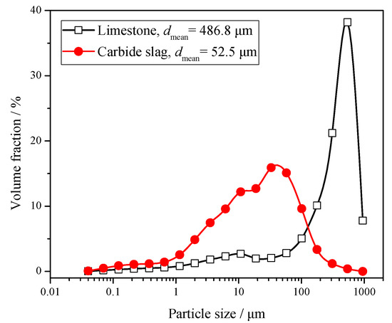
Figure 1.
Particle size distribution (PSD) of limestone and carbide slag.
2.2. Brief Introduction of 1 MWth Pilot Boiler and 690 t·h−1 CFB Boiler
In order to better study the feasibility of using carbide slag as the alternative desulfurizer in a CFB furnace, experiments were carried out on a 1 MWth pilot-scale boiler and a 690 t·h−1 industrial boiler, respectively. The influence of different operating parameters, including bed temperature, types of desulfurizer, Ca/S mole ratio of limestone, and carbide slag on the desulfurization reactions in furnace are discussed in detail.
The schematic diagram of a 1 MWth pilot CFB boiler is shown as Figure 2. The height of the furnace was 23 m, which was close to the typical height of the industrial CFB furnaces, ensuring the sufficient burn-out time of fuel particles. The cross-section of the air distributor was 0.175 m × 0.351 m, whereas the cross size of dilute phase zone was 0.351 m × 0.351 m. There were some groups of additional water-cooled tubes on the top of the dilute phase zone. The temperature of each zone in the furnace could be effectively controlled by adjusting the flow rate of cooling water in heating surfaces. A total of 43 thermocouples and 32 pressure or differential pressure measuring points were arranged in the system to monitor its operating conditions.
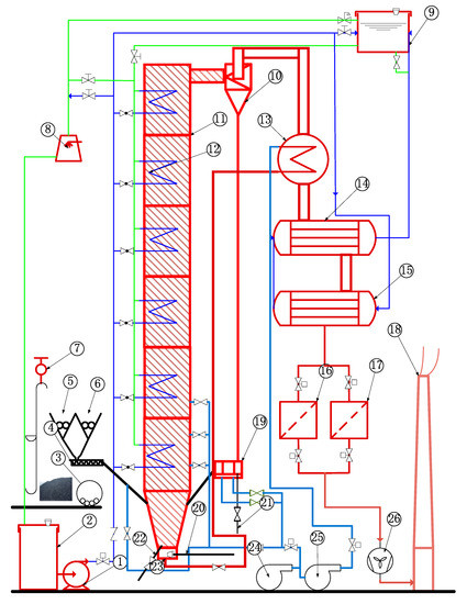
Figure 2.
Schematic diagram of 1 MWth pilot CFB boiler system. 1. Feed water pump, 2. cooling water tank, 3. fuel crusher, 4. screw conveyor, 5. coal silo, 6. limestone silo, 7. motor hoist, 8. blowing cooling tower, 9. cooling water tank at high level, 10. cyclone, 11. furnace, 12. water cooling surface, 13. air heater, 14. first economizer, 15. second economizer, 16. dust collector I, 17. dust collector II, 18. chimney, 19. U-type loop seal, 20. starting burner, 21. circulating ash pipe, 22. bottom ash discharge pipe, 23. windbox, 24. air blower, 25. roots blower, and 26. induced draft fan.
In this experiment, the flue gas sampling point was arranged at the outlet of the cyclone. A PMA-10 oxygen sensor (M&C GmbH, Germany) was used to monitor the O2 concentration in the flue gas, with a resolution of 0.05%. The Rosemount™ NGA 2000 gas analyzer (Emerson Electric Co, USA), which has a good resolution (~1 ppm) for the target gases, was used for the measurements of CO, NO, and SO2.
The industrial-scale tests were carried out on a 690 t·h−1 CFB boiler, whose structure is shown in Figure 3, to verify whether the conclusions obtained from the pilot bench could be applied to larger industrial boilers. This boiler was manufactured by Shanghai Boiler Works, Ltd. The outlet pressure of superheat steam was 13.73 MPa, whereas the outlet temperatures of superheat and reheat steams were all 540 °C. Three cyclones were used in the boiler, and the furnace size was 37.5 m × 22.74 m × 7.845 m. The fluidization velocity was around 5 m·s−1 under the boiler maximum continuous rating (BMCR) condition and the ratio of primary to secondary air was about 6:4.
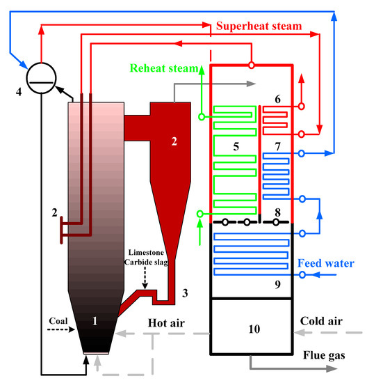
Figure 3.
Schematic diagram of 690 t·h−1 CFB boiler.1. Furnace, 2. cyclone, 3. loop seal, 4. drum, 5. reheater, 6. superheater, 7. high temperature economizer, 8. flue gas damper, 9. low temperature economizer, and 10. air heater.
3. Results and Discussion
3.1. Comparison of Reactivity between Limestone and Carbide Slag
In order to study the desulfurization activity of limestone and carbide slag, the calcination and sulfation tests of these two desulfurizer particles were carried out using a PRT-1 thermogravimetric analyzer (TGA, Beijing Optical Instrument Factory, China). In the calcination test, 100 mg of limestone or carbide slag particles with a given size (0.25–0.425 mm) were calcined under an air atmosphere, respectively. The reactor temperature was raised from room temperature to 1100 °C at a rate of 20 °C min−1. The flow rate of reaction gas was kept constant at 0.5L min−1. Figure 4 shows the differential thermogravimetry (DTG) curves of limestone and carbide slag during the calcination process. The two curves are quite different. Only one peak can be found from the limestone curves, which was caused by the thermal decomposition of CaCO3. It decomposed from 637 to 851 °C and reached its maximum decomposition rate at 827 °C. Weight loss of carbide slag calcination was divided into two parts. In the first stage, weight loss of Ca(OH)2 decomposition took 6 min. The initial and final decomposition temperatures were 406 and 515 °C, respectively. The maximum reaction rate was 4.00 mg·min−1 and the corresponding temperature was 479 °C. In the second stage, weight loss of CaCO3 decomposition lasts for 11 min. The initial and final decomposition temperatures were 604 and 782 °C, respectively. The maximum reaction rate was 3.90 mg·min−1 and the relevant temperature was 750 °C. Carbide slag exceeded limestone in desulfurization performance. Carbide slag was decomposed to CaO above 400 °C which matches the reaction of SO2 generation form coal, whereas limestone is decomposed to CaO at higher temperature and does not react quickly.
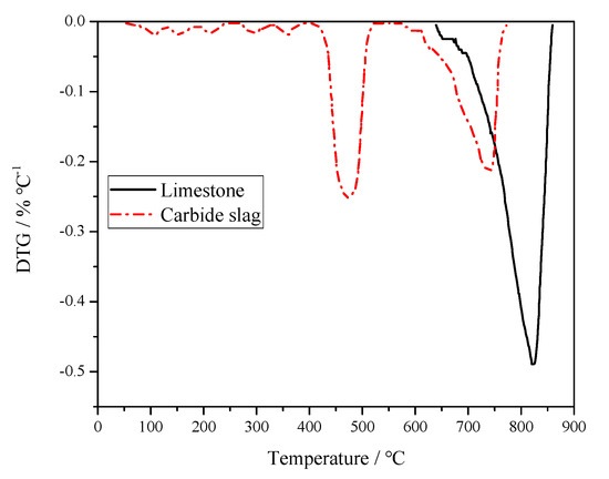
Figure 4.
Derivative Thermogravimetry (DTG) curves of limestone and carbide slag during calcination process.
During the calcination process, the release of CO2 will form some pores on the surface and inside of particles [18]. These pores create the pathways for the diffusion of SO2 into the interior of particles and the occurrence of desulfurization reactions. Different pore structure will significantly affect the reactivity of limestone or carbide slag. SO2 and O2 molecules diffuse from the CaO surface into the micropores. Then these molecules are absorbed and gradually diffused through the product layer to reach the unreacted CaO layer [19]. Therefore, the specific surface area, specific pore volume, and pore size distribution will directly affect the sulfation process and the reaction rate of CaO particles. The specific surface area reflects the size of the gas–solid reaction interface, whereas the specific pore volume reflects the size of the diffusion space for the gas molecule. Since CaSO4 has a larger molar volume than CaCO3 and CaO (52.2, 36.9, and 16.8 cm3 mol−1, respectively) [20], the produced CaSO4 blocks the pores, leaving a large amount of unreacted CaO inside the particles, and reducing the utilization of the desulfurizer [21]. For the CaO with large pore size, the blockage can be delayed and the effective reaction time will be prolonged. The pore properties of calcined limestone and carbide slag samples are determined by a low-temperature N2 adsorption method. The pore structure parameters and pore size distributions of different desulfurizers could be obtained by using the appropriate calculation model. The Brumauer–Emmett–Teller (BET) method [22] is the most commonly used method for determining the pore surface area and distribution of porous materials, while the specific pore volume of the desulfurizer is calculated by the Barrett-Joyner-Halenda (BJH) equation [23], which is based on the Kelvin and Halsey equation.
Based on the data measured by the BELsorp Mini II analyzer (Microtrac-BEL Crop., Japan), the pore structure parameters were calculated. The comparison of specific surface area, specific pore volume, and average pore size of calcined limestone and carbide slag particle are shown as Figure 5. The larger specific surface area and specific pore volume indicate that the calcined carbide slag is more likely to react with SO2 than the calcined limestone. Carbide slag has a lot of Ca(OH)2 while limestone has a lot of CaCO3. During decomposing, both will release CaO. However, CaO decomposed from Ca(OH)2 has better porosity and specific area than that from CaCO3. So carbide slag may have better desulfurization performance.
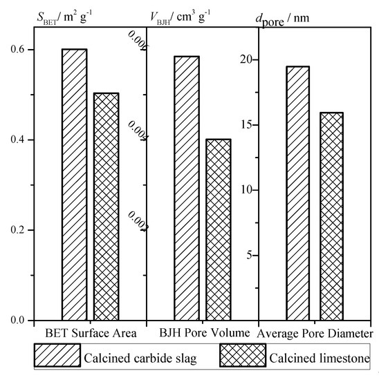
Figure 5.
Surface area, pore volume, and pore diameter of calcined products.
The sulfation tests of the calcined products were also carried out on the TGA to compare the desulfurization capacity of these two desulfurizers. The reactor temperature was 850 °C, and the simulated flue gas was used as the reaction gas with a flow rate at 0.5 L min−1. The balanced gas (N2), 5% of O2, and 3000 ppm SO2, were monitored separately by the flow meters and well mixed in the gas tank before feeding into the reactor. Figure 6 presents the CaO conversion rate of these two desulfurizers. Compared with previous studies [24], the CaO conversion rate of both desulfurizers was relatively low. The particles in this study were a bit larger (0.25–0.425 mm) than those in previous studies, which may have caused the bad mass transfer between gas and solid to slow down the sulfation rate of CaO. It can be seen from Figure 7 that as the reaction proceeded, the curve for limestone flattened, which meant the reaction gradually slowed down. The CaSO4 formed by the sulfation reaction covered the surface of particles, clogging the micro-pores, and hampering the further reactions of limestone. With the reaction proceeding, its mechanism switched from the initial kinetics-controlled mode to the diffusion-controlled mode. The sulfation rate mainly depended on the diffusion of reactants or solid ions in the produced CaSO4 layer, which is consistent with the study of Las et al. [25] The CaO conversion curve of carbide slag was almost a straight line and it was higher than that of limestone at the reaction time because the reaction time of 60 min was much longer than that of desulfurization reaction in furnace. This indicates that the sulfation of carbide slag was always in the kinetics-controlled stage during the whole sulfation process. The well-developed pore structure of calcined carbide slag brings higher reactivity to its sulfation. Khan et al. [26] found that the H2O released during the calcination created and enlarged pores in Ca(OH)2, which exposed greater surface areas for subsequent sulfation reactions. Borgwardt [27] and Silcox et al. [28] found that the small-particle limestone calcination reaction produced a richer pore structure, a larger specific surface area, and a higher reaction rate in the sulfurization reaction. Laursen et al. [29,30] found that the addition of alkali metal ions improved the sulfur capture capacity of limestone. Thus the higher content of K2O may also promote the sulfation of carbide slag. García-Martínez et al. [31] found that the thermal treatment of Ca(OH)2 formed CaO sorbents with high activity to retain SO2. Nowak and Mirek [3] summarized the research results of predecessors and found that the sulfation rate and sulfation degree of a limestone particle were the function of many parameters, including limestone particle size, structure, porosity after calcination, temperature, gas velocity around the particle, and CaO content and impurities.
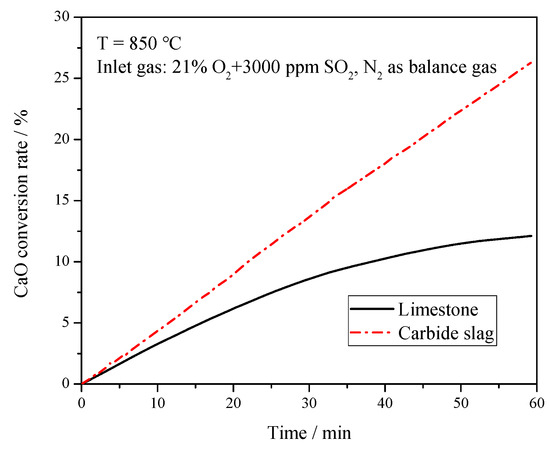
Figure 6.
CaO conversion rate of limestone and carbide slag during the sulfation process in the thermogravimetric analyzer (TGA).
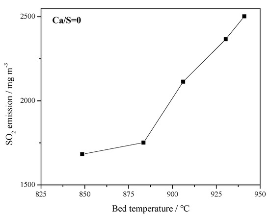
Figure 7.
Effect of bed temperature on original SO2 emissions in 1 MWth pilot circulating fluidized bed (CFB) boiler (Ca/S = 0).
3.2. The 1MWth Pilot CFB boiler Tests
Because of the similar heat and mass transfer characteristics to the industrial furnace and the flexibility of boiler operation, the 1 MWth pilot CFB boiler gives us a tool to explore the effects of different operating parameters on the performance of desulfurizers. Anthony et al. [32] found that the factors affecting the desulfurization in the limestone furnace mainly included the molar ratio of calcium to sulfur, temperature, reaction atmosphere, limestone reactivity, and limestone particle size.
The Ca/S mole ratio of carbide slag and limestone can be calculated as
where mlim is the Ca/S mole ratio of limestone; Blim is the limestone consumption, t·h−1; ηCaCO3 is the CaCO3 content in limestone, %; Bcoal is the coal consumption, t·h−1; and Sar is the sulfur content in coal, %.
where mcs is the Ca/S mole ratio of carbide slag; Bcs is the carbide slag consumption, t·h−1; and ηCa(OH)2 is the Ca(OH)2 content in carbide slag, %.
Figure 7 presents the effect of bed temperature on the original SO2 emission. The SO2 concentration increased with increasing bed temperature in the range of 845–945 °C, which is also the typical combustion temperature of CFB boilers. Since CaCO3 or CaO are one of the main components in coal ash, it has self-desulfurization ability during the combustion process [33]. When the temperature increases over 900 °C, the high temperature may cause the sintering of coal ash and the re-decomposition of the produced CaSO4, resulting in a rise in SO2 emission. Therefore, from the perspective of emission control, the bed temperature must be controlled within a reasonable range.
Figure 8 shows the SO2 emission concentrations at different Ca/S mole ratios. It can be seen that the desulfurization efficiency can be improved to a certain extent with the increase of Ca/S mole ratio. In Figure 8a, with the increase of Ca/S molar ratio of limestone, SO2 emission could be reduced but SO2 emission increased rapidly with the increase of bed temperature. At the bed temperature of 940 °C, the desulfurization effect of limestone with low Ca/S molar ratio was limited, and the SO2 concentration was more than 2000 mg·m−3. However, for Figure 8b, increasing the Ca/S mole ratio of carbide slag had a more obvious impact on improving desulfurization efficiency. A low SO2 emission could be reached by adding more desulfurizer into the furnace even at a relatively high temperature. But for limestone or carbide slag, there is an optimum temperature range. When the temperature grows over 910 °C, the desulfurization efficiency decreased rapidly. Compared with the limestone, the carbide slag had higher content of Fe2O3 and SiO2 (seen from Table 2), which can form the glassy ferric oxide and silicate with high-temperature resistance [34] and prevent the further decomposition of CaS and CaSO4. General speaking, the carbide slag was less sensitive to the bed temperature than the limestone. Its desulfurization efficiency was still high even at 940 °C, which meant the carbide slag had stronger resistance to sintering. Compared with Figure 8a,b, it can be seen that the desulfurization performance of the carbide slag was significantly better than that of the limestone.
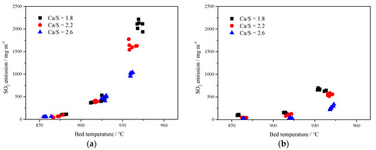
Figure 8.
Effect of bed temperature and Ca/S mole ratio on SO2 emissions in 1 MWth pilot CFB boiler; (a) limestone, (b) carbide slag.
3.3. The 690 t·h−1 CFB Boiler Field Tests
Saastamoinen [35] found that small particles were reactive but they had a short residence time depending on the separation efficiency of the cyclone. With large particles, the residence time was longer, but the rate and degree of sulfur capture were lower. Therefore, the structure of the cyclone vortex finder of the 690 t·h−1 CFB boiler is retrofitted, which is shown in Figure 9. Because the three separators are of exactly the same size, only one of them is drawn. As can be seen from Figure 10, PSD of fly ashes in the 690 t·h−1 CFB boiler had been greatly improved. The particle size of limestone and carbide slag during the 690 t·h−1 CFB boiler test was close to that of the 1MWth pilot CFB boiler. Because the desulfurizer supply point was different, the results of the 690 t·h−1 CFB boiler test and the 1MWth pilot CFB boiler test were different. Overall, the limestone and the carbide slag had worse desulfurization performance in the 690 t·h−1 CFB boiler than in the 1MWth pilot CFB boiler.
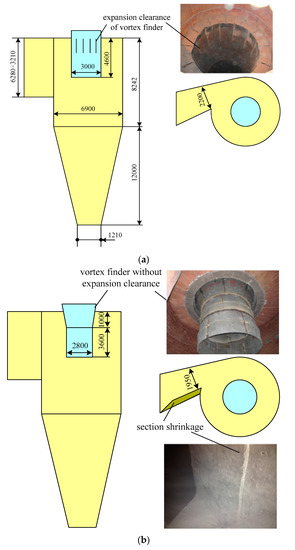
Figure 9.
Structure of cyclone inlet duct and vortex finder; (a) original design, (b) retrofit design.
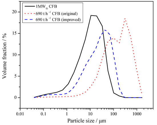
Figure 10.
Particle size distribution (PSD) of fly ashes obtained from 1 MWth pilot CFB boiler and 690 t·h−1 CFB boilers.
Table 3 is the matrix of field tests on the 690 t·h−1 CFB boiler. In all the tests, the bed temperature was maintained around 915 °C for at least 4 h. Figure 11 shows the bed temperature curve and the original emission of SO2 without any desulfurizer addition. The average SO2 concentration was 2515 mg·m−3. In the test, it was found that even temperature increases of 10–15 °C brought about a large increase in the SO2 emission.
Table 3.
Matrix of field tests on the 690 t·h−1 CFB boiler.
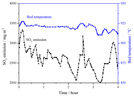
Figure 11.
Bed temperature on original SO2 emissions in 690 t·h−1 CFB boiler (Ca/S = 0).
Figure 12 shows the average SO2 emission for all the field tests. When Ca/S = 2, SO2 concentration with limestone addition was 949 mg·m−3 (showen in Table 3, test 2-1), whereas for carbide slag this concentration increased to 1044 mg·m−3 (test 3-1, original design of cyclone vortex finder) and decreased to 743 mg·m−3 (test 3-3, improved design of cyclone vortex finder). For Ca/S = 3, the three corresponding values for SO2 concentration were 586 mg·m−3 (test 2-2), 884 mg·m−3 (test 3-2, original design of cyclone vortex finder), and 342 mg·m−3 (test 3-4, improved design of cyclone vortex finder). That means in the 690 t·h−1 CFB boiler, the desulfurization efficiency of carbide slag was higher than that of limestone after the cyclone modification. Besides the bed temperature and desulfurizer type, the most important factor for the desulfurization efficiency is the effective residence time of desulfurizer in the furnace [36,37], which largely depends on the particle size and separation efficiency of cyclones. From Figure 10, it is obvious that the mean particle size of fly ash in the 1 MWth pilot CFB boiler was smaller than that in the 690 t·h−1 CFB boiler, which meant that the separation efficiency of cyclone in the 1 MWth pilot CFB was higher. The finer carbide slag particles could build an effective circulation route and prolong the residence and reaction times in the furnace. Before the cyclone modification for the 690 t·h−1 CFB boiler, large amounts of carbide slag particles were smaller than the cutting size of the cyclones because of the lower separation efficiency. After being added to the furnace, and passing through the furnace, the finer particles could not be captured by the cyclone. Therefore, in order to utilize the carbide slag as a resource and achieve better desulfurization efficiency, it is necessary to modify the structure of cyclone and improve its separation efficiency.
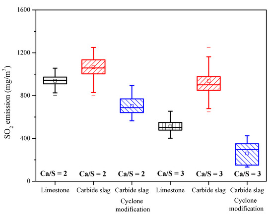
Figure 12.
The SO2 emission for each condition of field tests.
4. Conclusions
The desulfurization experiments were carried out on TGA, a 1 MWth pilot CFB boiler, and a 690 t·h−1 boiler to explore the feasibility of carbide slag as an alternative in-bed desulfurizer for the coal-fire CFB plant. The following conclusions can be drawn:
(1) Compared with the limestone, the carbide slag had significantly finer particle size and a lower calcination temperature. Its calcined product had a better pore structure and desulfurization activity. The sulfation of carbide slag was always in the kinetics-controlled stage during the whole sulfation process.
(2) The carbide slag exhibited higher desulfurization efficiency in the pilot tests, which is conducive to saving the amount of desulfurizer. At the same time, it had better sintering-resistance properties, which makes it possible to effectively control SO2 emissions even at high combustion temperatures (> 910 °C).
(3) The mean size of carbide slag was only 52.5 μm. Therefore, different results appeared in the field test. When the separation efficiency of the cyclone was low, the desulfurization efficiency of carbide slag was inferior than limestone. When the separation efficiency of the cyclone was high, the desulfurization efficiency of the carbide slag was better than limestone.
(4) The desulfurization efficiency of carbide slag with the same Ca/S mole ratio was higher than that of limestone after cyclone vortex finder modification. When Ca/S = 2, the average SO2 emission concentration using carbide slag was 78.3% of limestone, and for Ca/S = 3, the result was 58.4%.
Author Contributions
Writing—Review & Editing, Z.H., J.L. and L.D.; Project administration, D.C.
Funding
This study was supported by the Beijing Nova Program (XX2018033).
Acknowledgments
Lin Chen and Lei Tan provided valuable advice on the study idea and write-up.
Conflicts of Interest
The authors declare no conflict of interest. The funders had no role in the design of the study; in the collection, analyses, or interpretation of data; in the writing of the manuscript, and in the decision to publish the results.
Abbreviations
| Aar | ash content in coal as received basis (%) |
| Bcoal | coal consumption (t·h−1) |
| Bcs | carbide slag consumption (t·h−1) |
| Blim | limestone consumption (t·h−1) |
| Car | carbon content in coal as received basis (%) |
| FCar | fixed carbon content in coal as received basis (%) |
| Har | hydrogen content in coal as received basis (%) |
| Mar | moisture content in coal as received basis (%) |
| mcs | Ca/S mole ratio of carbide slag (−) |
| mlim | Ca/S mole ratio of limestone (−) |
| Nar | nitrogen content in coal as received basis (%) |
| Oar | oxygen content in coal as received basis (%) |
| Sar | sulfur content in coal as received basis (%) |
| Var | volatile content in coal as received basis (%) |
| ηCaCO3 | CaCO3 content in limestone (%) |
| ηCa(OH)2 | Ca(OH)2 content in carbide slag (%) |
References
- Yue, G.; Cai, R.; Lu, J.; Zhang, H. From a CFB reactor to a CFB boiler—The review of R & D progress of CFB coal combustion technology in China. Powder Technol. 2017, 316, 18–28. [Google Scholar]
- Rydén, M.; Hanning, M.; Corcoran, A.; Lind, F. Oxygen Carrier Aided Combustion (OCAC) of Wood Chips in a Semi–Commercial Circulating Fluidized Bed Boiler Using Manganese Ore as Bed Material. Appl. Sci. 2016, 6, 347. [Google Scholar] [CrossRef]
- Nowak, W.; Mirek, P. Circulating fluidized bed combustion. In Fluidized Bed Technologies for Near-Zero Emission Combustion and Gasification; Scala, F., Ed.; Woodhead Publishing Series in Energy: Cambridge, UK, 2013; pp. 701–764. [Google Scholar]
- Basu, P. Combustion and Gasification in Fluidized Beds; CRC Press: Boca Raton, FL, USA, 2006. [Google Scholar]
- Ahlstrom Pyropower. Activation/Reuse of Fluidized Bed Waste: Phase I—Literature Review; Report to the Canadian Electrical Association; Centre for Energy Advancement through Technological Innovation (CEATI) Project 9131 G 891; CEATI: Montreal, QC, Canada, 1992. [Google Scholar]
- Ehrlich, S. A coal-fired fluidized bed boiler. In Proceedings of the Institute of Fuel Symposium, 1975; pp. C4-1, C4-10. [Google Scholar]
- Fields, R.B.; Burdett, N.A.; Davidson, J.F. Reaction of sulfur dioxide with limestone particles: The influence of sulfur-trioxide. Trans. Inst. Chem. Eng. 1979, 57, 276–280. [Google Scholar]
- Zhao, S.; Duan, Y.; Yao, T.; Liu, M.; Lu, J.; Tan, H.; Wang, X.; Wu, L. Study on the mercury emission and transformation in an ultra—Low emission coal—Fired power plant. Fuel 2017, 199, 653–661. [Google Scholar] [CrossRef]
- Yin, G.; Ning, C.; Fu, X. Development of sulfur fixation and ombustion-supporting agent for llose coal using red mud and black liquor of papermaking. Environ. Eng. 2004, 22, 57–59. [Google Scholar]
- Li, Y.; Sun, R.; Zhao, J.; Han, K.; Lu, C. Sulfation behavior of white mud from paper manufacture as SO2 sorbent at fluidized bed combustion temperatures. J. Therm. Anal. Calorim. 2012, 107, 241–248. [Google Scholar] [CrossRef]
- Liu, J.; Wu, X.; Cheng, J.; Zhou, J.; CaO, X.; Cen, K. The desulfurization characteristics of industrial wastes during coal combustion. ACTA Sci. Circumstantiae 2000, 20, 790–793. [Google Scholar]
- Yu, S.; Wu, Z. Comparative study on desulfurization performance of several alkaline waste slags. Environ. Eng. 2002, 20, 42–44. [Google Scholar]
- Cheng, J.; Zhou, J.; Liu, J.; Cao, X.; Cen, K. Physicochemical Characterizations and Desulfurization Properties in Coal Combustion of Three Calcium and Sodium Industrial Wastes. Energy Fuels 2009, 23, 2506–2516. [Google Scholar] [CrossRef]
- Xie, X.; Li, Y.J.; Liu, C.T.; Wang, W.J. HCl absorption by CaO/Ca3Al2O6 sorbent from CO2 capture cycles using calcium looping. Fuel Process Technol. 2015, 138, 500–508. [Google Scholar] [CrossRef]
- Tao, X.; Zhang, G.; Zhang, P.; Wang, S.; Nabi, M.; Wang, H. Thermo—Carbide slag pretreatment of energy plants for enhancing enzymatic hydrolysis. Ind. Crops Prod. 2018, 120, 77–83. [Google Scholar] [CrossRef]
- Wu, S.; Li, Y.; Zhao, J.; Lu, C.; Wang, Z. Simultaneous CO2/SO2 adsorption performance of carbide slag in adsorption/desorption cycles. Can. J. Chem. Eng. 2015, 94, 33–40. [Google Scholar] [CrossRef]
- Lyngfelt, A.; Leckner, B. Sulphur capture in circulating fluidized—Bed boilers: Can the efficiency be predicted. Chem. Eng. Sci. 1999, 54, 5573–5584. [Google Scholar] [CrossRef]
- Zhang, Y.; Sun, Q.; Cao, L.; Geng, J. Pore, mechanics and acoustic emission characteristics of limestone under the influence of temperature. Appl. Therm. Eng. 2017, 123, 358–368. [Google Scholar] [CrossRef]
- Chen, L.; Wang, C.; Wang, Z.; Anthony, E.C. The kinetics and pore structure of sorbents during the simultaneous calcination/sulfation of limestone in CFB. Fuel 2017, 208, 203–213. [Google Scholar] [CrossRef]
- Newton, G.H.; Chen, S.L.; Kramlich, J.C. Role of porosity loss in limiting SO2 capture by calcium based sorbents. AIChE J. 1989, 35, 988–994. [Google Scholar] [CrossRef]
- Borgwardt, R.H.; Bruce, K.R.; Blake, J. An investigation of product—Layer diffusivity for calcium oxide sulfation. Ind. Eng. Chem. Res. 1987, 26, 1993–1998. [Google Scholar] [CrossRef]
- Brunauer, S.; Emmett, P.; Teller, E. Adsorption of gases in multimolecular layers. J. Am. Chem. Soc. 1938, 60, 309–319. [Google Scholar] [CrossRef]
- Masthan, S.; Rao, K.; Prasad, P.; Rao, P. Derivation of the expanded form of the BJH equation and its application to the pore structure analysis of mesoporous adsorbents. Adsorpt. Sci. Technol. 1992, 9, 212–230. [Google Scholar] [CrossRef]
- Basu, P. Circulating Fluidized Bed Boilers—Design, Operation and Maintenance; Springer International Publishing: Basel, Switzerland, 2015. [Google Scholar]
- Las, O.M.; Diego, L.F.; GARCÍA-LABIANO, F.; Rufas, A.; Abad, A.; Gayán, P.; Gayán, J. Modeling of limestone sulfation for typical oxy—Fuel fluidized bed combustion conditions. Energy Fuels 2013, 27, 2266–2274. [Google Scholar]
- Khan, T.; Lee, Y.Y. Improving Limestone Utilization Circulation Fluidized Bed Combustors through the Reactivation and Recycle of Partially Utilized Limestone in the Ash; ASME: New York, NY, USA, 1995; pp. 831–840. [Google Scholar]
- Borgwardt, R.H. Calcination kinetics and surface area of dispersed limestone particles. AIChE J. 1985, 31, 103–111. [Google Scholar] [CrossRef]
- Silcox, G.D.; Kramlich, J.C.; Pershing, D.W. A mathematical model for the flash calcination of dispersed calcium carbonate and calcium hydroxide particles. Ind. Eng. Chem. Res. 1989, 28, 155–160. [Google Scholar] [CrossRef]
- Laursen, K.; Grace, J.; Lim, C. Enhancement of the Sulfur Capture Capacity of Limestones by the Addition of Na2CO3 and NaCl. Environ. Sci. Technol. 2001, 35, 4384–4389. [Google Scholar] [CrossRef] [PubMed]
- Laursen, K.; Ker, A.; Grace, J.; Lim, C.J. Characterization of the enhancement effect of Na2CO3 on the sulfur capture capacity of limestones. Environ. Sci. Technol. 2003, 37, 3709–3715. [Google Scholar] [CrossRef] [PubMed]
- García-Martínez, J.; Bueno-López, A.; García-García, A.; Linares-Solano, A. SO2 retention at low temperatures by Ca(OH)2—Derived CaO: A model for CaO regeneration. Fuel 2003, 81, 305–313. [Google Scholar] [CrossRef]
- Anthony, E.J.; Granatstein, D.L. Sulfation phenomena in fluidized bed combustion systems. Progress Energy Combust. Sci. 2001, 27, 215–236. [Google Scholar] [CrossRef]
- Lasek, J.; Kazalski, K. Sulfur Self—Retention during Cocombustion of Fossil Fuels with Biomass. Energy Fuels 2014, 28, 2780–2785. [Google Scholar] [CrossRef]
- Siagi, Z.; Mbarawa, M.; Mohamed, A.; Lee, K.T.; Dahlan, I. The effects of limestone type on the sulphur capture of slaked lime. Fuel 2007, 86, 2660–2666. [Google Scholar] [CrossRef]
- Saastamoinen, J.J. Particle—Size optimization for SO2 capture by limestone in a circulating fluidized bed. Ind. Eng. Chem. Res. 2007, 46, 7308–7316. [Google Scholar] [CrossRef]
- Scala, F.; Salatino, P. Limestone fragmentation and attrition during fluidized bed oxyfiring. Fuel 2010, 89, 827–832. [Google Scholar] [CrossRef]
- Scala, F.; Salatino, P. Attrition of limestones by impact loading in fluidized beds: The influence of reaction conditions. Fuel Process. Technol. 2010, 91, 1022–1027. [Google Scholar] [CrossRef]


© 2019 by the authors. Licensee MDPI, Basel, Switzerland. This article is an open access article distributed under the terms and conditions of the Creative Commons Attribution (CC BY) license (http://creativecommons.org/licenses/by/4.0/).