Article

An Automatic Marker–Object Offset Calibration Method for Precise 3D Augmented Reality Registration in Industrial Applications

1
Institute of Intelligent Manufacturing and Information Engineering, School of Mechanical Engineering, Shanghai Jiao Tong University, Shanghai 200240, China
2
Chengdu Aircraft Industry (Group) Co. Ltd. of Aviation Industry Corporation of China, Chengdu 610092, China
*
Authors to whom correspondence should be addressed.
Appl. Sci. 2019, 9(20), 4464; https://doi.org/10.3390/app9204464
Submission received: 8 September 2019 / Revised: 12 October 2019 / Accepted: 17 October 2019 / Published: 22 October 2019
(This article belongs to the Special Issue Augmented Reality: Current Trends, Challenges and Prospects)

Abstract

:

Featured Application

The proposed method provides a universal calibration tool of marker–object offset matrix for marker-based industrial augmented reality applications. Given an industrial product or part attached with one fiducial marker and its CAD model, the method automatically calculates the offset matrix between the CAD coordinate system and the marker coordinate system to achieve the global optimal AR registration visual effect. The method is applicable to all marker-based industrial AR applications.

Abstract

Industrial augmented reality (AR) applications demand high on the visual consistency of virtual-real registration. To present, the marker-based registration method is most popular because it is fast, robust, and convenient to obtain the registration matrix. In practice, the registration matrix should multiply an offset matrix that describes the transformation between the attaching position and the initial position of the marker relative to the object. However, the offset matrix is usually measured, calculated, and set manually, which is not accurate and convenient. This paper proposes an accurate and automatic marker–object offset matrix calibration method. First, the normal direction of the target object is obtained by searching and matching the top surface of the CAD model. Then, the spatial translation is estimated by aligning the projected and the imaged top surface. Finally, all six parameters of the offset matrix are iteratively optimized using a 3D image alignment framework. Experiments were performed on the publicity monocular rigid 3D tracking dataset and an automobile gearbox. The average translation and rotation errors of the optimized offset matrix are 2.10 mm and 1.56 degree respectively. The results validate that the proposed method is accurate and automatic, which contributes to a universal offset matrix calibration tool for marker-based industrial AR applications.

1. Introduction

Augmented reality (AR) superimposes rich visual information on the real-world scene, which is intuitively suitable for guiding or training manual operations in the manufacturing industry. However, AR has not fully broken the industrial market yet, because it lacks pervasiveness from the standpoint of industrial users [1], and this paper addresses one related issue that is commonly confronted at the beginning of setting an industrial AR application.
To achieve precise user cognition, industrial AR applications require that the rendered virtual information should be spatially consistent with the real scene or target object. In AR applications, the process that aligns the rendered virtual information in the spatially consistent position is defined as the AR registration [2]. Because monocular cameras are the most cost-effective for industrial users, monocular AR registration methods have drawn much attention from the research field. The mechanism of the AR registration is shown in Figure 1, where the registered AR view is generated by projecting the virtual 3D graphics using the same intrinsic and extrinsic parameters as that of the real camera [3]. Therefore, the AR registration accuracy is determined by two matrices, one is the camera’s intrinsic matrix that is obtained by camera calibration [4], and the other is the extrinsic matrix that is obtained by 6DoF (6 degrees of freedom) camera pose estimation or tracking.
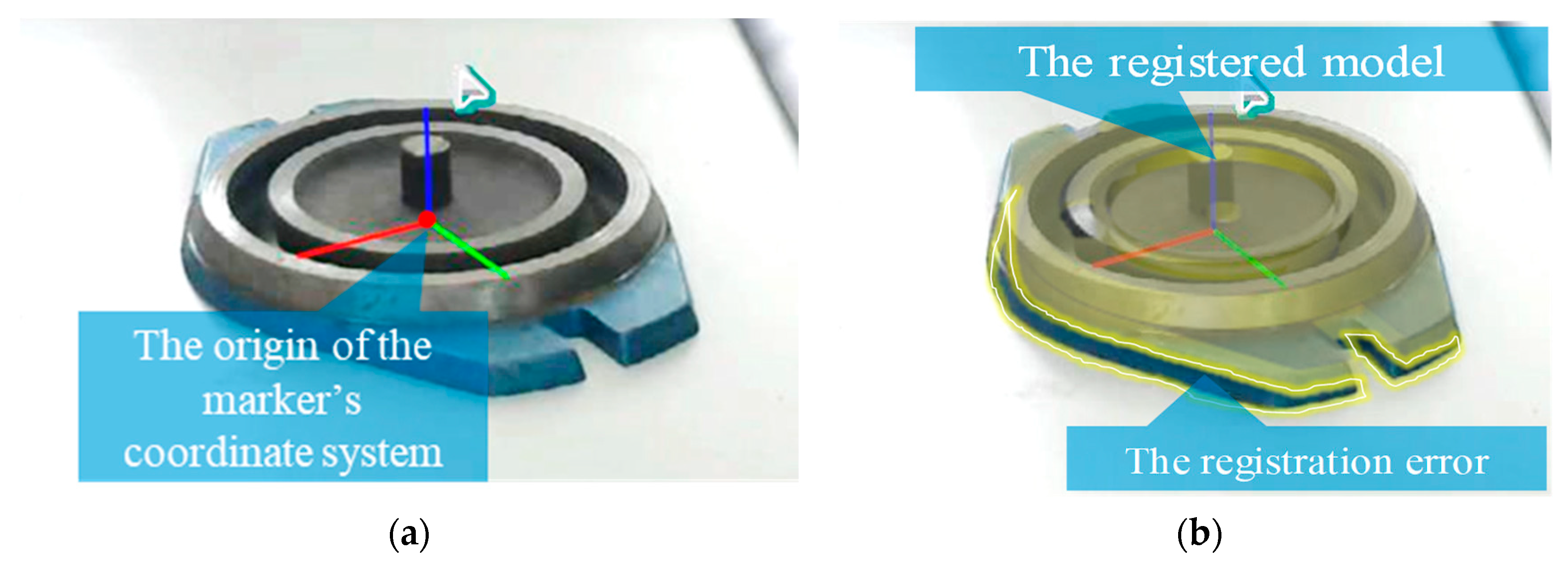
As reported by several significant reviews on the industrial AR applications [5,6], the marker-based method is accurate, robust, convenient, and requires no specific knowledge on AR or computer vision, therefore it takes the predominant position in obtaining the extrinsic matrix for industrial AR applications. The marker-based method directly takes the measured 6D camera pose relative to the marker center as the extrinsic matrix, and then project the virtual graphical object based on the assumption that the object’s local coordinate system coincides with that of the marker’s [7]. However, the assumption does not always hold true in practical conditions, which leads to obvious visible AR registration error as illustrated in Figure 2b.
Three reasons have been observed to cause the registration error from our previous work [8,9]:
  • Generally, the marker’s coordinate system is assumed to coincide with the local coordinate system of the CAD model, but in the practical condition, the marker may be laid on other planar surfaces of the object, which introduces an undetermined transformation between the planned layout position and the real layout position of the marker.
  • Though the transformation could be set manually, it is calculated by multiplying several manually measured transformation matrix, which brings in the systematic measurement error.
  • Given both the manual marker layout and the transformation measurement are accurate, the AR registered CAD model will still not be perfectly aligned with the real object because of the slight structure, shape, or appearance changes caused by the machining or assembling errors.
When a marker is attached to the target object, all the above errors are fixed as both the marker and the object are rigid in the 3D space. Those errors are combined and defined as the marker–object offset matrix [8], which is independently calibrated before the online tracking to compensate for the extrinsic matrix. The calibration problem is equivalent to the image alignment problem [10] for they both solve the transformation parameters that align two images taken from one target object toward the minimal visual discrepancy. The early stage of the image alignment method [10,11] employs the homography transformation or affine transformation model between the two images. Such models are linear and only work when the images contain the same static target object and allow little camera view-point changes. The method also requires an approximate initial guess of the transformation parameters, then solves the parameters by iteratively optimizing a non-linear objective function that describes the visual discrepancy between the template image and the re-aligned image. The accuracy of the method depends on the initial guess and the transformation scale when the initial parameters are far from the true value or the transformation is too large to approximate to the homography or affine model, the method would fail into a local minimum. Such adverse conditions are common in the 2D–3D image alignment applications such as face alignment [12,13], scene/object alignment [14,15,16,17,18], and volumetric medical image alignment [19,20].
To avoid the influence of initial parameters, face alignment methods use landmark points along the face contour in both 2D and 3D dimensions to build the objective function [12]. By facilitating the landmarks as the shape prior, Liu F et al. [13] applied a cascaded coupled-regressor to update the 2D landmarks and the 3D face shape iteratively, achieving the state-of-art accuracy in current 2D-3D face alignment methods.
For general 3D objects, shape priors like face landmarks are unavailable, therefore the researchers designed the objective functions using the image features like edge [14], intensity texture [15], surface normal [16], or object structure [21]. By combining the feature tracker and the robust estimator, the image-feature-based objective functions are effective to solve the small and temporal continuous non-linear rigid transformations. However, when the tracker is lost, those methods would fail because of re-initialization errors. Among those image features, the strong gradient feature proposed by Wuest H et al. in [14] and the descriptor filed proposed by Crivellaro A et al. in [15] have already built a numerical connection between the 2D image and the 3D model of one 3D object, which are able to address the alignment problem if a transformation prior is provided.
Besides the global objective functions, discrete transformation models have also been studied to tackle the non-linear transformations. A classic method is the mutual information based image registration (MI) [18], which calculates the mutual information of the image partitions by histogramming their joint intensities or using a kernel estimator for the joint density. According to the deep analysis of MI presented by Tagare, H.D. et al. [19], the performance of MI is highly related to the partition strategy of the target object and the configuration of the histogram bin, which are experimentally chosen according to its application object. Domokos C et al. [20] also used a discrete model to address the global non-linear transformation between an original 3D object and its broken fragments. The method assumes that each fragment complies an affine model and solves the parameters by a polynomial equation, which greatly increases the computation cost. Another way to solve the non-linear transformation is to use regression models trained by deep neural networks [16,17,22]. However, both the universality and accuracy of the learning-based method are limited by the quantity and quality of the training data, which is hard to be generalized on objects out of the training dataset.
To sum up, given an approximate parameter prior, the image-feature-based objective function is a relatively feasible method to solve the non-linear 2D–3D image alignment for an industrial product. Aiming at eliminating the three types of errors, this work integrates both the marker pose prior and the gradient feature to calculate an approximate prior of the offset matrix, then optimize the prior parameters using the dense descriptor to achieve the minimal alignment error. Finally, the offset matrix describing the rigid transformation between the marker coordinate system and the object coordinate system is precisely calibrated to support the marker-based AR registration.
The rest of the paper is organized as follows. Section 2 presents an overview of the proposed automatic marker–object offset matrix calibration method and then details the key procedures to realize the method. Section 3 presents both quantitative and qualitative validation of the proposed method on the publicity dataset and mechanical parts from an automobile gearbox. Section 4 discusses the potentials and limitations revealed by the experimental results. Finally, the conclusions and future perspectives are drawn in Section 5.

2. Materials and Methods

2.1. Overview of the Proposed Method

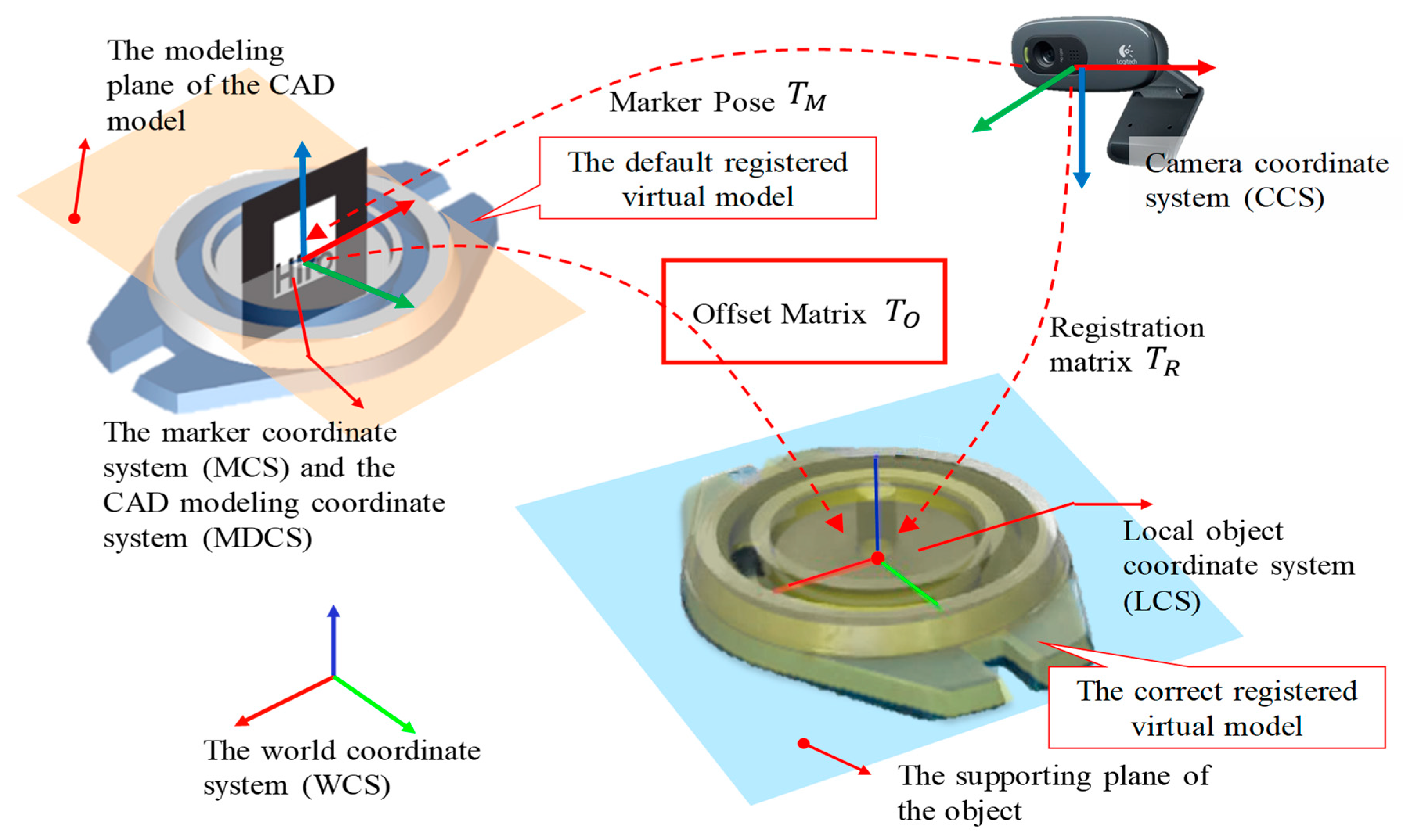
This paper aims to calibrate and compensate the marker–object offset matrix to realize a perfect alignment AR registration visual effect. To generalize the method, the coordinate systems used in this paper are presented in Figure 3.
In industrial AR applications, the default CAD modeling coordinate system (MDCS) is assumed to coincide with the marker coordinate system (MCS). In the real scene, the coordinate of the real object is denoted as LCS, which is defined on the supporting plane of the object. Because the MDCS usually locates on the first modeled plane of the product, the default registered virtual model at MCS exists as an offset from the real object at LCS. The undetermined transformation between MCS(MDCS) and LCS in the camera coordinate system (CCS) is then denoted as the offset matrix T O . Given the calibrated T O , the registration matrix T R could be calculated by:
T R = T M T O
The problem is then formulated as follows: given an image containing a tracking marker and the CAD model, T O is estimated which minimizes a registration error function E ( T R ) . In the Cartesian coordinate system, T O is a 4 × 4 matrix that has 6 degrees of freedoms (DoFs); to simplify the problem, this paper transforms T O = [ R O , t O ] into a 6DoF vector v O = [ θ v x , θ v y , θ v z , t x , t y , t z ] T using the exponential map minimal parameterization [23]. The mapping relationship between T O and v O is given in Equations (2) and (3).
R O = [ 2 ( v x 2 1 ) s 2 + 1 2 v x v y s 2 2 v z c s 2 v x v z s 2 + 2 v y c s 2 v x v y s 2 + 2 v z c s 2 ( v y 2 1 ) s 2 + 1 2 v y v z s 2 2 v x c s 2 v x v z s 2 2 v y c s 2 v y v z s 2 + 2 v x c s 2 ( v z 2 2 ) s 2 + 1 ] ,
t O = [ t x , t y , t z ] .
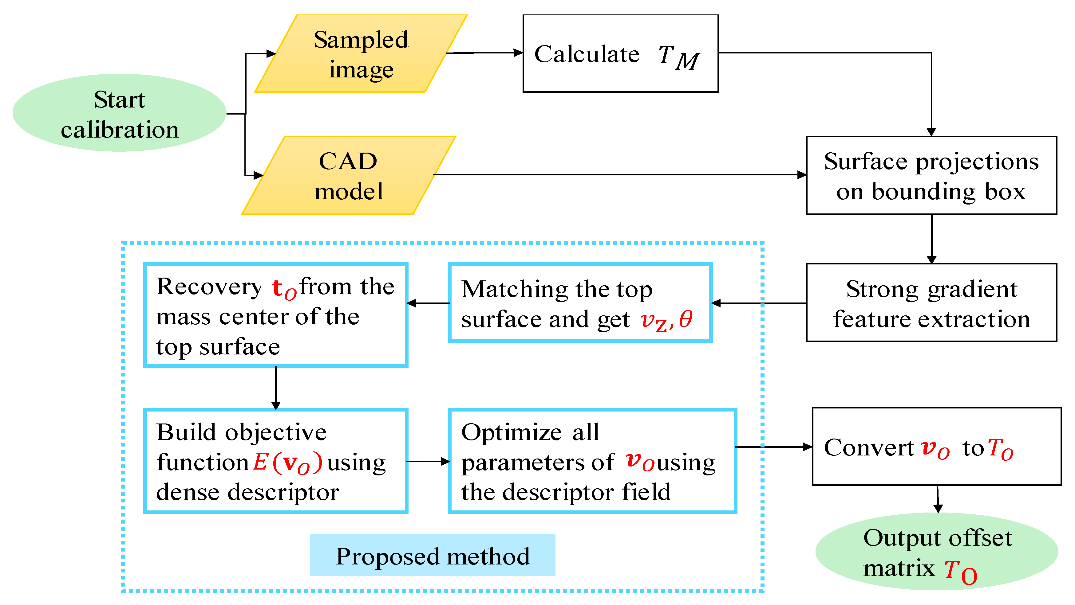
This paper then derives all six parameters by four procedures as shown in Figure 4, and the details are presented in the following subsections.

2.2. Normal Estimation

For an industrial product, one 3D bounding box (BBX) with six surfaces is available from its CAD model. The method starts with matching the supporting plane and its normal direction from the six surfaces of the BBX. In practical condition, the supporting plane of the product is determined on one surface of the bounding box but is invisible in the camera captured image I c . Therefore, the supporting plane and its normal is searched using features extracted from the visible part of the object. Given the marker pose T M calculated from I c , the CAD model is projected six times in a virtual environment using T M as the view matrix. In each time of projection, the LCS is transformed to the center of one BBX surface to align the surface with the marker. The projected images are denoted as the template images { I t 1 , I t 2 , , I t 6 } , which contains one true solution of the normal direction. One example of the projection results is shown in Figure 5.
In the projected template image, four corner points on the top surface of the BBX are recorded to construct the region of interest (ROI) area. After the projection, all six template images are cropped into their projected BBX size to form the new template images { I R 1 , I R 2 , , I R 6 } that only contain information about the target object. Then, dominant orientation templates (DOT) [24] of strong image gradient is extracted from I c and { I R 1 , I R 2 , , I R 6 } to perform the template matching. The template matching slides the template image on I c to find the position with maximum similarity. The similarity score is computed using the following equation:
ε ( I c , I R , c ) = r P | cos ( ori ( I R , r ) -ori ( I c , c + r ) ) | ,
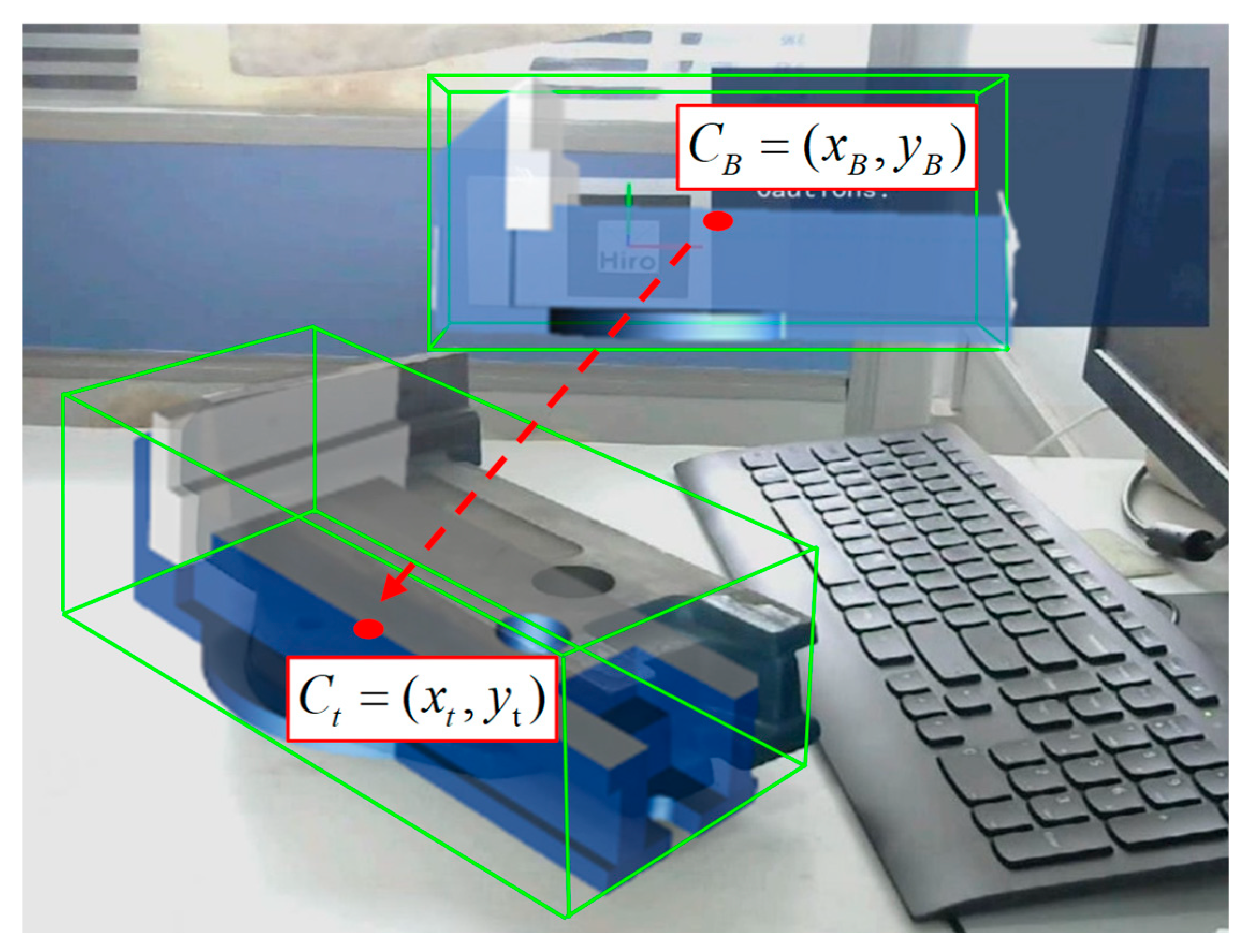
where ori ( I R , r ) is the gradient at the pixel coordinate r on I R and c is the location of the center of I R on the target image I c . The template image that has the highest similarity score is recognized to have the most approximate normal direction, and the corresponding BBX transformation matrix respective to the MCS(MDCS) is recorded as T o 1 . The matching position of the bounding box projection on I c is recorded as C t = ( x t , y t ) .

2.3. Translation Estimation

By estimating the most approximate normal direction, the corresponding BBX and the matching image position C t = ( x t , y t ) are also obtained. To align the projected model with the matched object, the virtual camera is translated along the vector C t C B regarding the projection viewer. Because of the translation is performed in the 3D virtual projection environment, the scale of the model keeps unchanged, but the view angle is transformed according to the 3D translation operation. The 3D translation scale is calculated by the proportion of C t C B with the pixel size l M of the marker in I c , which are both available. Therefore, the translation offset matrix T o 2 could be expressed by:
T o 2 = [ 1 0 0 C t C B l M ( x t x B ) 0 1 0 C t C B l M ( y t y B ) 0 0 1 0 0 0 0 1 ] ,
and the projection matrix after the translation is:
T R = T M T o 1 T o 2 .
After the translation of the virtual camera, the CAD model is coarsely aligned with the image ROI of its corresponding real product as shown in Figure 6.

2.4. Global Optimization

Given the initial guess of the registration pose with the approximate normal direction and translation, the problem of solving the remained offset T Δ is equivalent to solving the pose transformation of the virtual camera that makes the image area of the projected CAD model completely superimposed with that of the imaged object. The problem is solved under a 3D image alignment framework [11,15,25] by optimizing an image registration error function regarding the pose parameters, which is shown as follow:
E ( vec ( T R ) ) = 1 n i = 1 n ( O ( I c , x i ) O ( I R , ( W ( x i , vec ( T R T Δ ) ) ) ) 2 ,
where O ( ) is a series of operations on I c and I R to minimize the registration error E ( T R ) , vec ( ) is the exponential map minimal parameterization of a 4 × 4 size pose matrix, T R is the transformed projection matrix in Equation (6), x i = [ u i , v i , 1 ] T is the projected point of the 3D object point X = [ U i , V i , W i , 1 ] T , n is the number of densely sampled pixels on I c and I R . Different from the computation method of O ( ) presented by Crevillaro A. et al. in [15], which uses a pixel intensity-based feature, this work continues to use the strong gradient features extracted in Section 2.2 to simplify the computation, as shown in Algorithm 1.
Algorithm 1 Calculation of the gradient based dense image descriptor O ( I )
Input: Image I , ROI rectangle R .
Output: Feature value arrays O ( I ) .
1:Extract ROI area R from I , note as I Rect .
2:Uniformly sample w × h points { x i } , i = 1 , 2 , , w × h on I Rect .
3:Convert I Rect type as double float gray scale image.
4:Calculate the Scharr gradient of I Rect as S x ( I Rect ) and S y ( I Rect ) .
5:Calculate the strongest gradients D O T ( . ) in S x ( I Rect ) and S y ( I Rect ) as D x ( I Rect ) and D y ( I Rect ) .
6:Composite D x ( I Rect ) and D y ( I Rect ) in one array D I ( I Rect ) .
7:For σ = 1 : 3 : 10 do
8:  Generate M = 4 pyramid images P ( I ) [ M ] of D I ( I Rect ) by P σ ( I ) = G σ D I ( I Rect )
9:End for
10:For M = 1 : 4 do
11:  For n = 1 : w × h do
12:    Get value at { x i } of P ( I ) [ M ] and store it in double float arrays O ( I )
13:  End for
14:End for
15:Return O ( I )
Substituting O ( ) in Equation (7), the objective function of the registration error E ( T R ) regarding T Δ is obtained. Consequently, T Δ that achieves the minimum E ( T R ) results in the maximum superimposing area. To solve T Δ in the non-linear E ( T R ) , an inverse compositional optimization framework is employed [25] using the first-order approximation [11] and Gauss–Newton iteration. By using the first-order approximation, Equation (7) is rewritten as:
E ( vec ( T Δ ) ) = 1 n i = 1 n ( O c ( W ( x i , vec ( T R ) ) ) + J E ( x i , vec ( T R ) ) vec ( T Δ ) O R ( x i ) ) 2 ,
where O c and O R are the dense gradient descriptor calculated using Algorithm 1 on I c and I R respectively. According to the Gauss–Newton optimization scheme, the solution of vec ( T Δ ) is:
vec ( T Δ ) = H E 1 ( vec ( T R ) ) i = 1 n J E T ( x t , vec ( T R ) ) ( O R ( x t ) O c ( W ( x t , vec ( T R ) ) ) ) ,
where J E and H E are the Jacobian matrix and the Hessian matrix of E ( T R ) , respectively. After solving T Δ each time, the T R is updated by:
T R = T M T o 1 T o 2 T Δ .
Repeat the computation of Equations (8)–(10) until vec ( T Δ ) converges to a small value, which is set as { ϵ } < 10 3 that considers both the convergence precision and speed, vec ( T Δ ) is then solved and the final Δ T is obtained by reverse mapping of vec ( T Δ ) by Equations (2) and (3). The global optimization will result in the minimal gradient difference E ( T M T O ) , which is equivalent to a maximum AR alignment area. An example of the optimization result is shown in Figure 7.

3. Results

The proposed marker–object offset matrix calibration method was evaluated in two aspects. First, its quantitative accuracy performance was evaluated by measuring the absolute pose error and the relative scale error on a publicity monocular 3D rigid tracking dataset provided by the École Polytechnique Fédérale de Lausanne (EPFL) [21,26]. Then, its qualitative performance in terms of the AR registration visual effect was evaluated on real images of the parts from an automobile gearbox. The hardware configuration of the experimental computer was a 3.1-GHz Intel Core i7-4770 CPU with 8 GB SDRAM memory, and the graphics card used was NVIDIA GeForce GT 620.

3.1. Quantitative Validation

3.1.1. Experiment Configuration

The EPFL monocular 3D rigid tracking dataset provides a simple CAD model of the object(.obj), several object videos with man-made disturbance, the camera’s intrinsic parameters, and the ground truth pose of the camera regarding the object reference system. Among the three test objects of the electric box, can, and door, the can object is made by texture-less and specular material that most approximates to an industrial part. Therefore, the can dataset was chosen to test the proposed method. The can dataset contains four training videos and two test videos. In three training videos, the can is surrounded by 14 ARUCO markers, and in the test videos, three markers are laid on the same side of the can. To acquire enough data to analyze the calibration accuracy, the training videos with 14 markers were selected as the experiment videos. The image size of the three experiment videos is 1920 × 1080, and the image frame numbers are 1248, 740, 1003 respectively. The materials provided in the can dataset are shown in Figure 8. The radius and the height of the can are 42 mm and 85 mm, respectively.

3.1.2. Results

The experiment was designed to perform on the three training videos with the can and 14 markers. Several markers were randomly occluded in some images because of the camera movement, and only T M of the valid markers were involved in the accuracy validation experiment. At the initial state, the LCS of the can was assumed to coincide with the center of each marker. For each experiment video, 14 offset matrices T = { T O 1 , T O 2 , , T O 14 } of each marker were calibrated once using the proposed method. The calibration was performed on 3–5 selected image frames to cover all the surrounding markers. The results were stored as a vector of matrices according to the marker ID. For all visible markers in the images of the experimental videos, the registration matrix was calculated by Equation (1), where T M was given by the tracking pose results of one ARUCO marker, and T O was given by T and the detected marker ID. The composed camera pose was compared with the ground truth pose by calculating the absolute error of the translation vector and the rotation vector. The absolute error results are shown in Table 1, where the unit of the | Δ x | , | Δ y | , | Δ z | is mm and the | Δ α | , | Δ β | , | Δ γ | is degree respectively. The average registration residue E ( T R ) of the 14 markers and the consuming time of the calibration process are also presented in Table 1. The error distribution results on the 6 degrees of freedom are shown in Figure 9.
According to the mean absolute error value in Table 1, the mean error value on all 6 degree of freedoms of the three experiment videos are 1.28 mm, 1.2 mm, 3.8 mm, 2.3°, 1.73°, 0.61° respectively, with the standard deviation of 0.92 mm, 0.51 mm, 2.18 mm, 0.63°, 0.58°, 0.20°. In Table 1 and Figure 9, | Δ α | and | Δ β | are much higher than | Δ γ | , for the estimation of the normal direction is directly determined by the supporting surface assumption while the other two rotation freedoms are the result of non-linear optimization. The error in Video2 and Video3 is obviously much higher than that of the video1 because of the blur and occlusion of the marker in the calibration image. The E ( T R ) reveals that the calibration error is mainly caused by the appearance domain differences between the CAD model and the real image of the target object.
To compare the influence of the calibration error, the relative scale error is defined in terms of the absolute size of the object as | Δ t | / l d i a g o n a l . As the diagonal of the bounding box is 105.4 mm, the relative scale error on translation is 1.9%, which is relatively small and neglectable to the human eye’s visual perception of the spatial position, meaning it fulfills the precision requirement for industrial AR applications.
In the aspect of time consumption, Video2 and Video3 also cost higher than Video1, because the initial normal and translation accuracy estimated by the DOT template matching was greatly influenced by the cluttered scene background and the relatively large error of the initial parameter guess further lowers the convergence speed of the non-linear optimization. However, because of the offset matrix calibration is off-line preparation work for AR applications, the calibration time of about 15 s in a complex scene is acceptable for industrial users.
The examples of AR registration visual effect using the calibrated T O in the three experiment videos are presented in Figure 10, Figure 11 and Figure 12 where the CAD model was registered using the T R calculated by the top-left marker in the image. It can be observed that the calibrated wireframe and the ground truth wireframe are nearly superimposed with each other, and the registered can model is perfectly aligned with the real object, which further demonstrates the effectiveness of the proposed method.

3.2. Qualitative Validation

3.2.1. Experiment Configuration

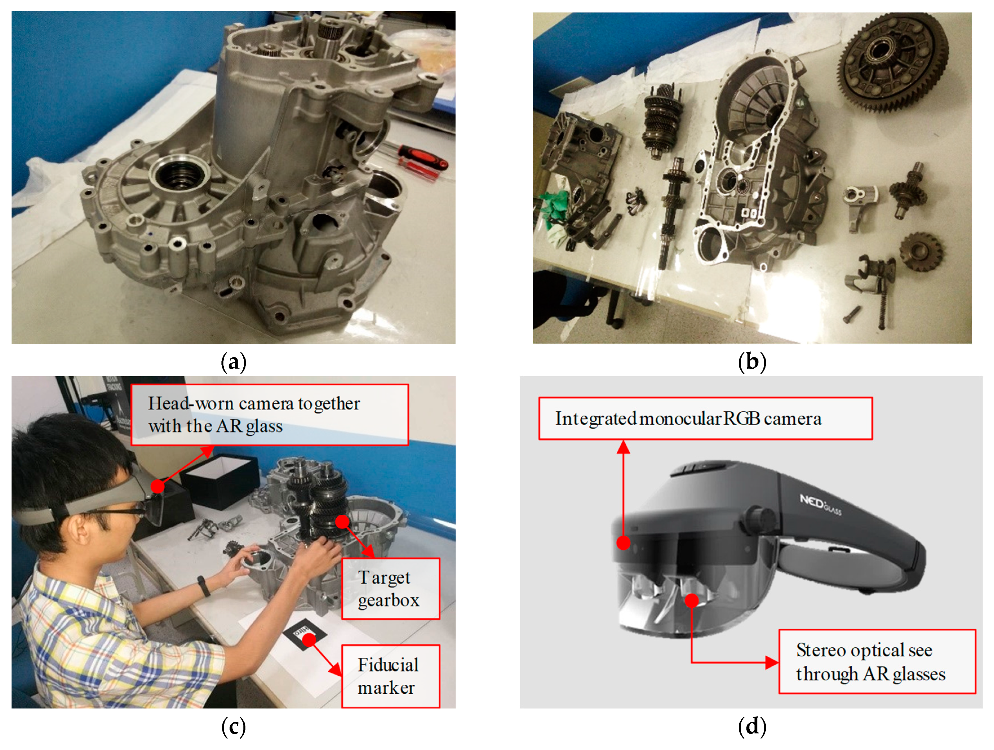
In real-world industrial AR applications, the visual registration effect directly influences the user experience and cognition. This work evaluated the registration performance of the proposed method on different size of industrial parts from a gearbox as shown in Figure 13 The camera used in the experiment was the integrated monocular RGB camera on a NED+ X1 AR Glass [27], and the experiment image resolution was set as 960 × 720. Three parts with supporting planes were selected to test the proposed method, they were a gear, a bracket, and a lower shell. The model and the test images were shown in Figure 14. At each calibration time, the operator put one selected part at the top left position with regard to the fiducial marker, then observed the automatic calibrated and registered model through the AR glass.

3.2.2. Results

The registration results of the two key stages in the calibration process are shown in Figure 15. The results of the initial offset matrix estimation using DOT matching are shown in the first column, and the results of the global parameter optimization of the offset matrix are shown in the second column. The results reveal that the optimization framework obviously improves the calibration accuracy compared with the DOT matching process. The proposed method has eliminated the trouble of double-image phenomenon in AR registration of texture-less and specular industrial parts by utilizing the proposed global gradient descriptor.

4. Discussion and Limitations

The experiments in Section 3 have verified the automatic property of the proposed marker–object offset matrix calibration method. The mean relative scale error that influences the global visual perception effect is 1.9%. The mean calibration time for the 1920 × 1080 experiment image is 12.23 s. Compared with the DOT method [24], the method directly estimates the 6D pose without any feature modeling and searching process by facilitating the normal direction prior. Compared with the existing SSD methods [15], the method replaces the continuous tracking pose prior by the estimated pose prior as the initial pose for optimization, which allows an accurate and fast pose re-initialization.
Two limitations are revealed from the experiment results. First, the convergence speed and the accuracy of the non-linear global optimization are greatly influenced by the errors of the initially estimated offset matrix, which is caused by the DOT matching in a cluttered image. The other limitation of the approach lies in the normal estimation which assumes that the supporting plane of the object coincides with one surface of the CAD model’s bounding box, which does not hold true for all shapes of industrial parts such as shafts. The two limitations will be addressed in our future work.

5. Conclusions and Future Perspectives

This research identifies three types of AR registration error in the marker-based AR applications. Aiming at solving the rigid errors automatically and precisely, this research defines an offset matrix to compensate the errors and proposes a two-stage approach to solve it. At the first stage, an initial guess of the offset matrix regarding the normal direction and the spatial translation is obtained by DOT template matching. At the second stage, the initial guess is globally optimized using a 3D image alignment framework. Experimental results demonstrated that the proposed approach is totally automatic, accurate, and applicable to calibrate the offset matrix. This work contributes to a universe and automatic offset matrix calibration tool that enables a free marker layout and calibration to initialize a marker-based industrial AR application scene. Though several limitations have been identified and discussed, the research is suitable for general industrial parts and acceptable in terms of the speed as a pre-processing step. In the future, surface segmentation and mutual information will be introduced to improve the accuracy and speed of the normal estimation, which may reduce the error for the global refinement. The approach is also promising to combine with keyframes-based marker-less AR applications, which will be further studied in our future work.

Author Contributions

Most of the conceptualization, methodology, software programming, resources, validation, formal analysis, investigation, data curation, visualization, and writing to original draft preparation were conducted by both X.Y. (Xuyue Yin) and X.Y. (Xu Yang). The supervision, project administration, and funding acquisition were conducted by X.F. and S.Q. Author Z.Z. offered the technical review and proof-reading of this manuscript.

Funding

This research was supported by the Chengdu Aircraft Industry (Group) Co. Ltd. of Aviation Industry Corporation of China (Grant No. 40113000050X) and was partially supported by the National Natural Science Foundation of China (Grant No.51705319), the Shanghai Academy of Spaceflight Technology (Grant No. USCAST2015-017).

Conflicts of Interest

The authors declare no conflicts of interest.

References

  1. Martinetti, A.; Marques, H.C.; Singh, S.; Van Dongen, L. Reflections on the Limited Pervasiveness of Augmented Reality in Industrial Sectors. Appl. Sci. 2019, 9, 3382. [Google Scholar] [CrossRef]
  2. Kim, K.; Billinghurst, M.; Bruder, G.; Duh, H.B.; Welch, G.F. Revisiting Trends in Augmented Reality Research: A Review of the 2nd Decade of ISMAR (2008–2017). IEEE Trans. Vis. Comput. Gr. 2018, 24, 2947–2962. [Google Scholar] [CrossRef] [PubMed]
  3. Lepetit, V.; Fua, P. Monocular model-based 3d tracking of rigid objects: A survey. Found. Trends Comput. Gr. Vis. 2005, 1, 1–89. [Google Scholar] [CrossRef]
  4. Zhang, Z. A flexible new technique for camera calibration. IEEE Trans. Pattern Anal. Mach. Intell. 2000, 22, 1330–1334. [Google Scholar] [CrossRef]
  5. Palmarini, R.; Erkoyuncu, J.A.; Roy, R.; Torabmostaedi, H. A systematic review of augmented reality applications in maintenance. Robot. Comput. Integr. Manuf. 2018, 49, 215–228. [Google Scholar] [CrossRef] [Green Version]
  6. Diao, P.-H.; Shih, N.-J. Trends and Research Issues of Augmented Reality Studies in Architectural and Civil Engineering Education—A Review of Academic Journal Publications. Appl. Sci. 2019, 9, 1840. [Google Scholar] [CrossRef]
  7. Kato, H.; Billinghurst, M. Developing AR Applications with ARToolKit. In Proceedings of the IEEE & ACM International Symposium on Mixed & Augmented Reality, Arlington, VA, USA, 2–5 November 2004. [Google Scholar]
  8. Yin, X.; Gu, Y.; Qiu, S.; Fan, X. Vr&ar combined manual operation instruction system on industry products: A case study. In Proceedings of the 2014 International Conference on Virtual Reality and Visualization, Shenyang, China, 30–31 August 2014; pp. 65–72. [Google Scholar]
  9. Yin, X.; Fan, X.; Zhu, W.; Liu, R. Synchronous AR assembly assistance and monitoring system based on ego-centric vision. Assem. Autom. 2019, 39, 1–16. [Google Scholar] [CrossRef]
  10. Baker, S.; Matthews, I. Equivalence and efficiency of image alignment algorithms. In Proceedings of the IEEE Computer Society Conference on Computer Vision and Pattern Recognition, Kauai, HI, USA, 8–14 December 2001; p. I-1090. [Google Scholar]
  11. Sharp, G.C.; Lee, S.W.; Wehe, D.K. Multiview registration of 3D scenes by minimizing error between coordinate frames. IEEE Trans. Pattern Anal. Mach. Intell. 2004, 26, 1037–1050. [Google Scholar] [CrossRef]
  12. Deng, J.; Roussos, A.; Chrysos, G.; Ververas, E.; Kotsia, I.; Shen, J.; Zafeiriou, S. The Menpo Benchmark for Multi-pose 2D and 3D Facial Landmark Localisation and Tracking. Int. J. Comput. Vis. 2018, 127, 599–624. [Google Scholar] [CrossRef] [Green Version]
  13. Liu, F.; Zhao, Q.; Liu, X.; Zeng, D. Joint Face Alignment and 3D Face Reconstruction with Application to Face Recognition. IEEE Trans. Pattern Anal. Mach. Intell. 2018. [Google Scholar] [CrossRef] [PubMed]
  14. Wuest, H.; Engekle, T.; Wientapper, F.; Schmitt, F.; Keil, J. From CAD to 3D Tracking—Enhancing & Scaling Model-based Tracking for Industrial Appliances. In Proceedings of the 2016 IEEE International Symposium on Mixed and Augmented Reality (ISMAR-Adjunct), Merida, Mexico, 19–23 September 2016; pp. 346–347. [Google Scholar]
  15. Crivellaro, A.; Verdie, Y.; Yi, K.M.; Fua, P.; Lepetit, V. [DEMO] Tracking texture-less, shiny objects with descriptor fields. In Proceedings of the 2014 IEEE International Symposium on Mixed and Augmented Reality (ISMAR), Munich, Germany, 10–12 September 2014; pp. 331–332. [Google Scholar]
  16. Bansal, A.; Russell, B.; Gupta, A. Marr revisited: 2d-3d alignment via surface normal prediction. In Proceedings of the IEEE Conference on Computer Vision and Pattern Recognition, Las Vegas, NV, USA, 26 June–1 July 2016; pp. 5965–5974. [Google Scholar]
  17. Loing, V.; Marlet, R.; Aubry, M. Virtual Training for a Real Application: Accurate Object-Robot Relative Localization Without Calibration. Int. J. Comput. Vis. 2018, 126, 1045–1060. [Google Scholar] [CrossRef] [Green Version]
  18. Viola, P.; Iii, W.M.W. Alignment by Maximization of Mutual Information. Int. J. Comput. Vis. 1997, 24, 137–154. [Google Scholar] [CrossRef]
  19. Tagare, H.D.; Rao, M. Why Does Mutual-Information Work for Image Registration? A Deterministic Explanation. IEEE Trans. Pattern Anal. Mach. Intell. 2015, 37, 1286–1296. [Google Scholar] [CrossRef] [PubMed]
  20. Domokos, C.; Kato, Z. Realigning 2D and 3D Object Fragments without Correspondences. IEEE Trans. Pattern Anal. Mach. Intell. 2016, 38, 195–202. [Google Scholar] [CrossRef] [PubMed]
  21. Crivellaro, A.; Rad, M.; Verdie, Y.; Moo Yi, K.; Fua, P.; Lepetit, V. A novel representation of parts for accurate 3D object detection and tracking in monocular images. In Proceedings of the IEEE International Conference on Computer Vision, Santiago, Chile, 7–13 December 2015; pp. 4391–4399. [Google Scholar]
  22. Crivellaro, A.; Rad, M.; Verdie, Y.; Yi, K.M.; Fua, P.; Lepetit, V. Robust 3D object tracking from monocular images using stable parts. IEEE Trans. Pattern Anal. Mach. Intell. 2018, 40, 1465–1479. [Google Scholar] [CrossRef] [PubMed]
  23. Grassia, F.S. Practical Parameterization of Rotations Using the Exponential Map. J. Gr. Tools 1998, 3, 29–48. [Google Scholar] [CrossRef]
  24. Hinterstoisser, S.; Lepetit, V.; Ilic, S.; Fua, P.; Navab, N. Dominant orientation templates for real-time detection of texture-less objects. In Proceedings of the 2010 IEEE Computer Society Conference on Computer Vision and Pattern Recognition, Francisco, CA, USA, 13–18 June 2010; pp. 2257–2264. [Google Scholar]
  25. Baker, S.; Matthews, I. Lucas-kanade 20 years on: A unifying framework. Int. J. Comput. Vis. 2004, 56, 221–255. [Google Scholar] [CrossRef]
  26. 3D Rigid Tracking from RGB Images Dataset. Available online: https://cvlab.epfl.ch/data/data-3d_object_tracking (accessed on 10 June 2019).
  27. Beijing Ned Ltd. Available online: http://www.nedplusar.com/en/index (accessed on 12 June 2019).
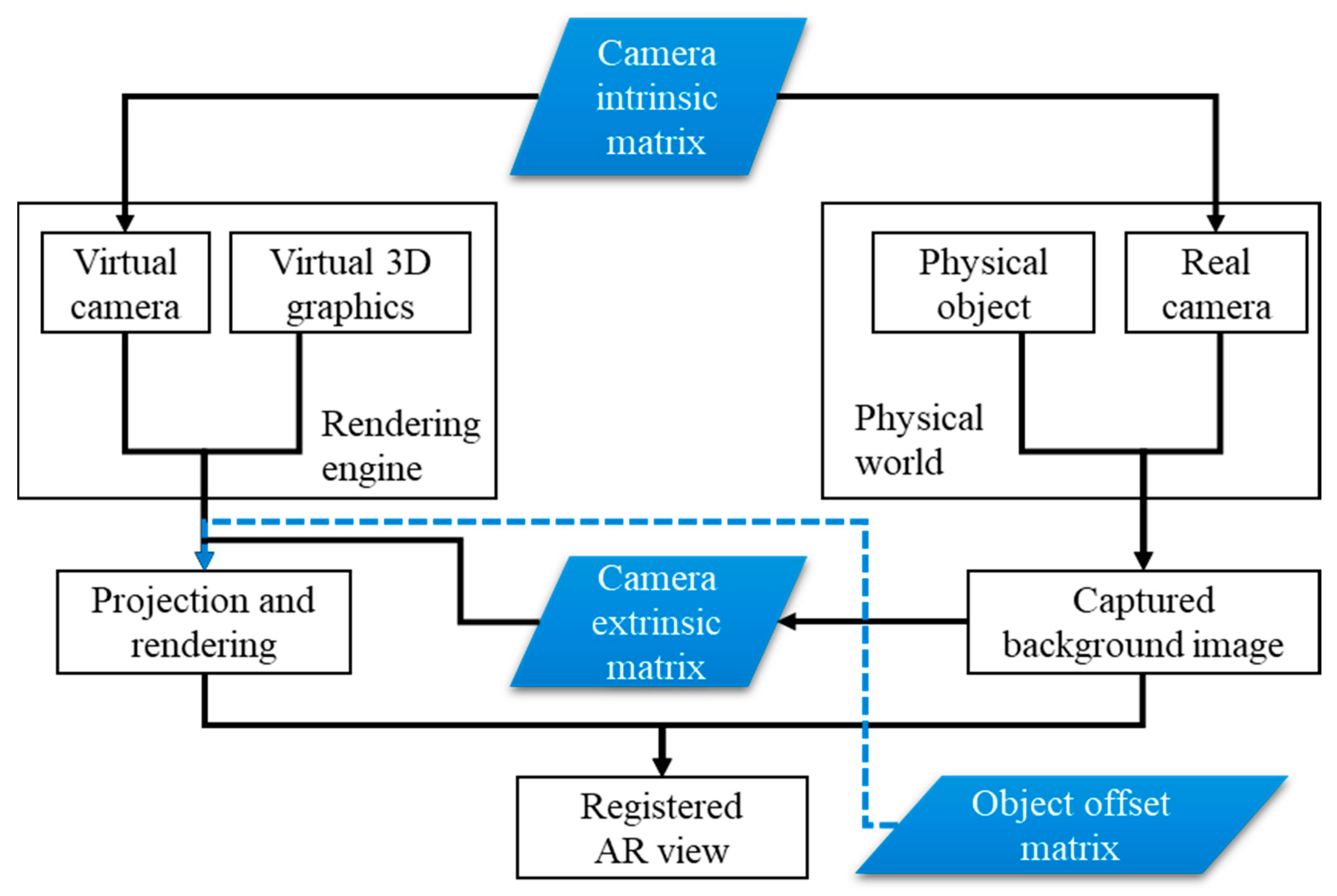
Figure 1. General vision-based augmented reality (AR) registration.
Applsci 09 04464 g001
Figure 2. The obvious visible registration error when assuming the model’s origin coincides with the marker’s origin. In this example, a 4 × 4 identity matrix is set as the offset matrix. (a) The origin coincidence assumption. (b) The visible registration error.
Applsci 09 04464 g002
Figure 3. The coordinate systems of an uncalibrated AR system.
Applsci 09 04464 g003
Figure 4. The outline of the offset matrix calibration method.
Applsci 09 04464 g004
Figure 5. Initial pose guesses obtained by the bounding box projection. (a) Six orthographic surfaces on the bounding box of a CAD model. (b) Perspective projection of bounding box (BBX) surfaces using TM.
Applsci 09 04464 g005
Figure 6. Initial pose guesses obtained by the bounding box projection.
Applsci 09 04464 g006
Figure 7. Final optimized TO and its corresponding AR registration effect.
Applsci 09 04464 g007
Figure 8. Materials provided in the can dataset that is used for testing the accuracy of the calibrated offset matrix. (a) The .obj format CAD model. (b) The real object appearance. (c) The image frame of Video1 that contains only the test object. (d) The image frame from Video2 that contains the test object with randomly man-made occlusions.
Applsci 09 04464 g008
Figure 9. The distribution of the calibration error of the three test videos.
Applsci 09 04464 g009
Figure 10. Marker-based AR registration results using the calibrated offset matrix on Video1. (a) The selected top-left ARUCO marker with a registered CAD model at the initial marker coordinate system (MCS) position. (b) The normal and translation guess of the top surface using dominant orientation templates (DOT) template matching. (c) The registration results using the calibrated offset matrix (in pink wireframe) and the ground truth pose (in green wireframe). (d) A cropped and enlarged region of interest (ROI) of the registration result.
Applsci 09 04464 g010
Figure 11. Marker-based AR registration results using the calibrated offset matrix on Video2. (a) The selected top-left ARUCO marker with a registered CAD model at the initial MCS position. (b) The normal and translation guess of the top surface using DOT template matching. (c) The registration results using the calibrated offset matrix (in pink wireframe) and the ground truth pose (in green wireframe). (d) A cropped and enlarged ROI of the registration result.
Applsci 09 04464 g011
Figure 12. Marker-based AR registration results using the calibrated offset matrix on Video3. (a) The selected top-left ARUCO marker with a registered CAD model at the initial MCS position. (b) The normal and translation guess of the top surface using DOT template matching. (c) The registration results using the calibrated offset matrix (in pink wireframe) and the ground truth pose (in green wireframe). (d) A cropped and enlarged ROI of the registration result.
Applsci 09 04464 g012
Figure 13. The experiment setup for the calibration of real industrial parts. (a) The assembled gearbox. (b) The component parts of the gearbox. (c) The experiment environment setup. (d) The head-worn AR glasses integrated with the monocular camera.
Applsci 09 04464 g013
Figure 14. Three examples of randomly laid industrial parts with regard to the marker. The first row is the CAD models, and the second row is the real part images.
Applsci 09 04464 g014aApplsci 09 04464 g014b
Figure 15. AR registration results using the initial pose obtained by DOT matching (the left column) and the optimized pose obtained by the non-linear optimization (the right column).
Applsci 09 04464 g015
Table 1. The absolute error of TR and the ground truth pose.
Experiment VideoMean Absolute Error E ( T R ) Time (s)
| Δ x | | Δ y | | Δ z | | Δ α | | Δ β | | Δ γ |
Video 10.430.690.932.251.390.490.186.24
Video 22.241.535.321.871.560.760.2315.62
Video 31.171.395.192.942.250.570.2114.83
Average1.2801.2033.8132.3531.7330.6070.20712.23