Article

Research on Virtual Inductive Control Strategy for Direct Current Microgrid with Constant Power Loads

School of Electrical Engineering, Zhengzhou University, Zhengzhou 450001, China
*
Author to whom correspondence should be addressed.
Appl. Sci. 2019, 9(20), 4449; https://doi.org/10.3390/app9204449
Submission received: 16 September 2019 / Revised: 5 October 2019 / Accepted: 18 October 2019 / Published: 20 October 2019
(This article belongs to the Special Issue DC & Hybrid Micro-Grids)

Abstract

:
In order to improve the stability of direct current (DC) microgrid with constant power loads, a novel virtual inductive approach is proposed in this paper. It is known that the negative impedance characteristic of constant power loads will lead to DC bus voltage fluctuation, which will be more serious when they integrate into the DC microgrid though a large transmission line inductive. For the convenience of analysis, a simplified circuit model of the system is obtained by modeling the distributed resources. Unlike the existing control strategies, the proposed control strategy constructs a negative inductance link, which helps to counteract the negative effects of the line inductive between the power source and the transmission line. Detailed performance comparison of the proposed control and virtual capacitance are implemented through MATLAB/simulink simulation. Moreover, the improved performance of the proposed control method has been further validated with several detailed studies. The results demonstrate the feasibility and superiority of the proposed strategy.

1. Introduction

There is no fluctuation of reactive power in the microgrid, and the stability of the direct current (DC) microgrid only depends on the stable operation of the bus voltage [1,2]. When the DC microgrid is operating in island mode, without the supporting of a large power grid, the instability of bus voltage will be more serious [3]. From the structural point of view, the island DC microgrid is a typical multi-source heterogeneous system containing multiple types of micro-resources and loads [4,5]. The stability is not only affected by the distributed resources, but also subjected to load, especially constant power loads (CPLs). Thus, how to eliminate the influence of the CPLs characteristics caused by the load converter and primary load is a technical challenge to ensure the stability of a DC microgrid [6].
To overcome the problem of voltage fluctuation caused by CPLs, the instability mechanism of CPLs has been widely studied and several solutions have been proposed [7,8]. In the past few years, some researchers have tried to solve such instability phenomena by a passive method [9,10,11]. Generally speaking, this method requires additional physical dampers. In [9], an LC (Inductive Capacitance) filter is added to the system. Although it shows a better effect, the system is based on an ideal model, which is different from the actual situation. And the response speed of the system is also affected to some extent. Based on the same idea, a physical filter containing multiple capacitors and resistors is applied to eliminate the impact of constant power loads [11]. However, the use of multiple resistors will make the power loss greater. Previous studies indicate that the power loss caused by passive damping makes it not suitable for DC microgrids. Therefore, the active control strategy gets more attention. This kind of method will not bring any additional physical dampers to the system, hence alleviating the system weight and efficiency problem. This is more in line with the requirements of efficient energy utilization in a DC microgrid. Furthermore, because of the advantages of distributed control, droop control has been widely used as an important form of active control [12,13,14,15].
Active control method can achieve the same effect as passive control strategy, but it will not cause additional power loss. Guo et al. added a low-pass filter in series to droop control, which can increase the output impedance of the converter in the low frequency range [16]. Thus, the bus voltage fluctuation caused by CPLs can be effectively alleviated. However, this research is limited to the introduction of filter designs. Furthermore, for solving the negative effects of CPLs, Wu et al. described a virtual phase-lead impedance stability control strategy [17]. The strategy was used to adjust the output impedance of CPLs to be positive. But it was not applied to an island mode. And from the point of inertia, a corresponding virtual capacitance control strategy was established by Zhu et al. [18]. And due to the increase of inertia by virtual capacitance, the robustness of system is increased in the face of CPLs. However, because the “plug-and-play” characteristics of distributed resources, new control strategies need to be designed for the access of new micro resources, which obviously lacks flexibility. In addition, other methods are also committed to using active control methods to improve system stability [19,20]. Among various approaches investigated in the literature, there is a deficiency that the influence of transmission line is not included in these study. This is imperfect, because the transmission line is also a major factor affecting the stability of the system, especially the inductance component of the transmission line [21,22].
To address the above problem, a virtual negative inductance control strategy is proposed in this paper. On the basis of droop control, a virtual inductive is constructed, which operates as a negative inductive link and counteracts the inductive in transmission line. Thus, the negative influence of line inductance is effectively solved. This paper makes the following contributions:
(1)
Through the modeling of micro-sources and loads, the system can realize the conversion from a multi-dimensional to a low-dimensional system.
(2)
An innovative solution of system instability is proposed from the perspective of line inductance. Compared with the virtual capacitance strategy in [18], the method proposed in this paper will be more smooth and fast in the process of adjustment.
(3)
The other salient feature of this paper is that starting from the transmission line, the strategy can be applied to a wide range of situations.
The remainder of the paper is organized as follows: The configuration and modeling of the DC microgrid is introduced in Section 2, and the simplified circuit model of the system is shown. Section 3 presents the design of the virtual inductive control strategy. In Section 4, simulation results are used to verify the superiority of the strategy by comparison and different case studies. Finally, Section 5 summarizes this paper and draws conclusions.

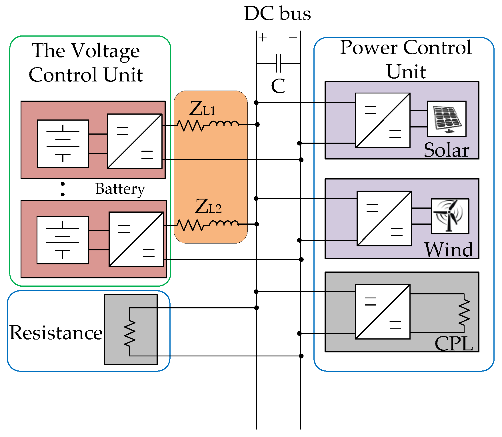
2. Structure and Modeling of Island DC Microgrid

The structure of an island DC microgrid is depicted in Figure 1, which mainly composes of four parts: (1) distributed resources (PV and wind turbine); (2) eEnergy storage unit; (3) various types of load (mainly divided into CPLs and resistive load); and (4) line impedance. Subsystems in the DC microgrid can also be divided into power control unit and constant voltage control unit according to their control mode [19]. The purpose of power control is to ensure that distributed generators inject constant power or maximum power into the system. In this paper, MPPT (maximum power point tracking) control was used for distributed generators such as wind turbines and PVs to achieve maximum power utilization. The constant voltage unit is aimed at stabilizing bus voltage [23]. For the energy storage unit, a droop control method is applied to the DC bus voltage [24].

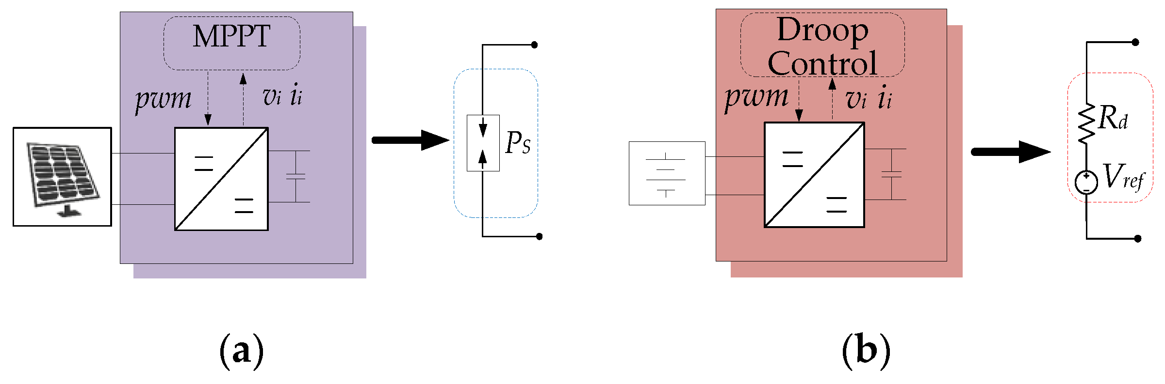
2.1. Modeling of Distributed Power Unit

The resources are connected to the DC microgrid through power converters, whose control dictates their behavior. Resources under MPPT try to maximize the injection of available power to the DC microgrid regardless of the network status. Under constant weather conditions, the power converter of distributed generation can be modeled as constant power sources (CPSs) when viewed by the bus terminals [5]. This means that despite of the variation on the bus voltage, the current provided by the power converter adapts to keep injecting constant power. Such distributed resources can be considered to be a type of CPLs with a negative power consumption, and both constant power loads and constant power sources can be totally modeled as an ideal constant power model, as illustrated in Figure 2a (taking the photovoltaic as an example). As CPLs and CPSs behave in the same way, they can be modeled as lumped CPLs that demand an equivalent constant power P given by (1). And based on [21], energy storage units based on the droop control are modeled as an ideal voltage source with series resistance, as illustrated in Figure 2b.
P = P C P L s + P C P S s P C P L s > 0   and   P C P S s < 0 ,

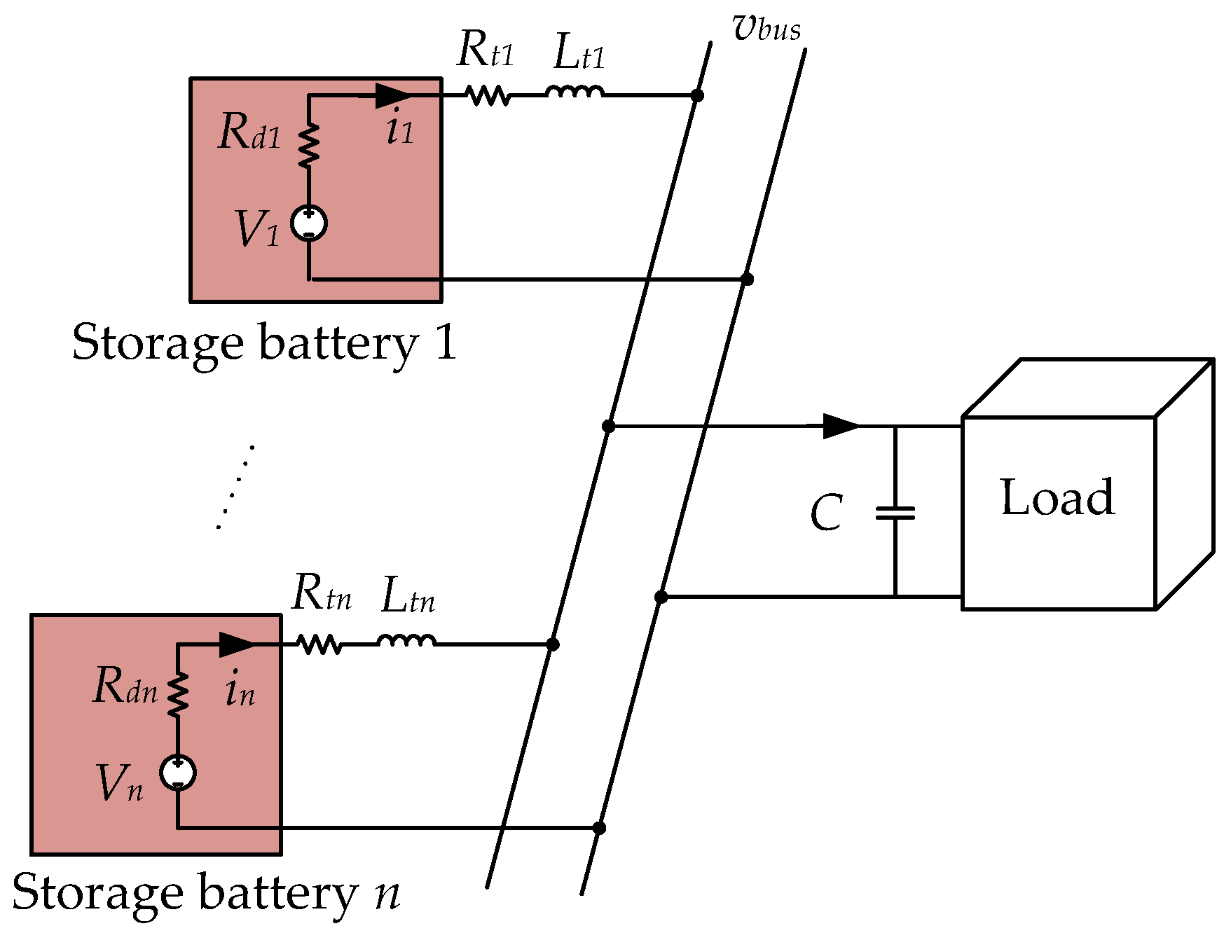
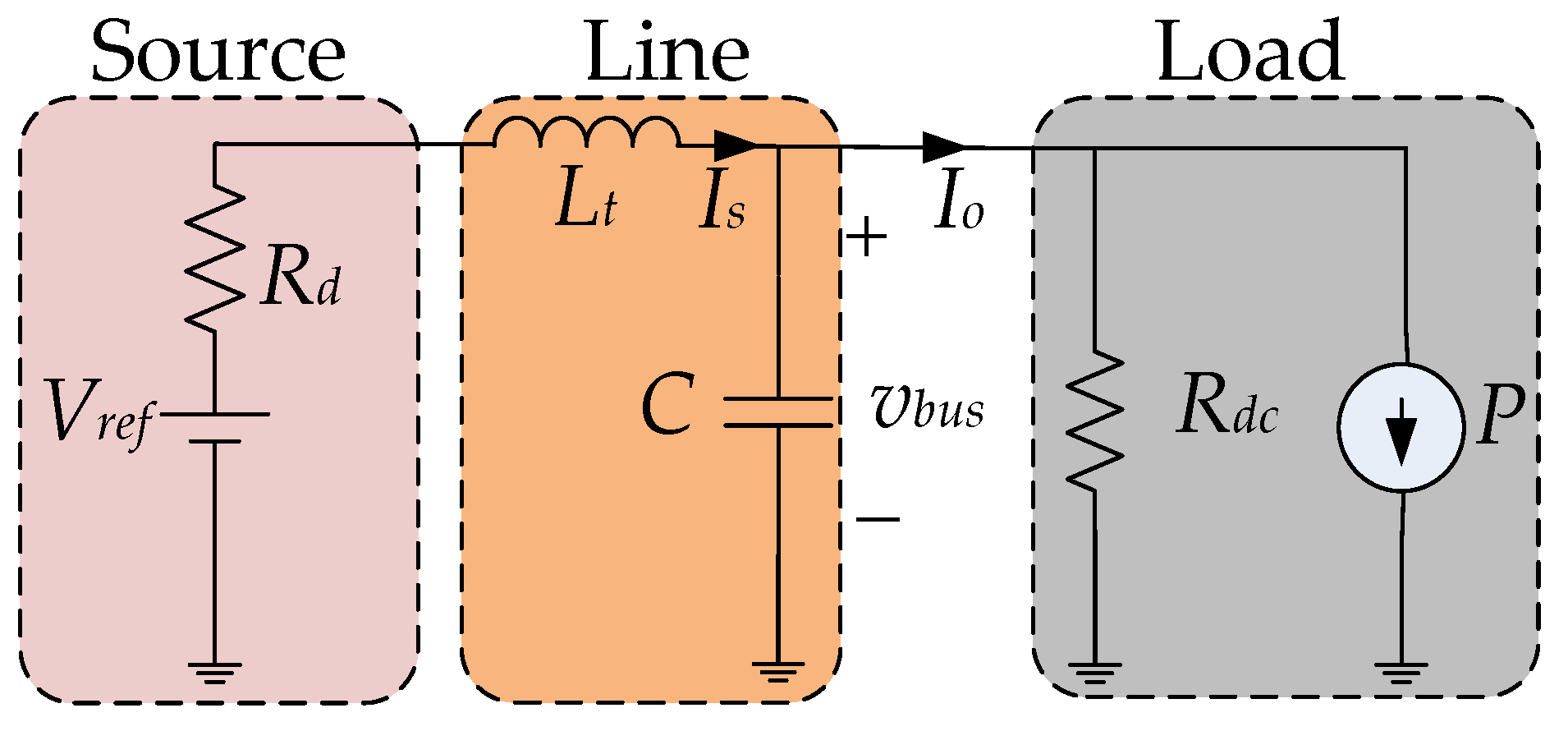
2.2. Dimension Reduction Modeling of Multi-Voltage Control Unit under Droop Control

On the basis of the work done above, the multi-branch combination model of DC microgrids with multiple voltage control units was obtained, as illustrated in Figure 3.
V i is the source voltage and v b u s is the voltage of the dc bus. R d i is the droop coefficient of the i th droop controller, R t i and L t i are the line resistance and inductance from i th energy storage unit to the bus, respectively. C is the equivalent capacitance on the bus [25]. The droop resistance and line resistance in series of the i th control unit can be represented by:
R i = R d i + R t i ,
Assume that the value of droop resistance is much greater than the line resistance, Equation (2) can be rewritten as:
R i R d i ,
As a complex multi-dimensional system, the DC microgrid power system is not conducive to analysis [26]. It is necessary to simplify the n-dimensional equation of representative DC microgrid system. Each distributed unit can be modeled as a differential equation in (4).
d i 1 d t = 1 L t 1 ( V 1 v b u s ) R d 1 L t 1 i 1 , d i 2 d t = 1 L t 2 ( V 2 v b u s ) R d 2 L t 2 i 2 , d i n d t = 1 L t n ( V n v b u s ) R d n L t n i n .
Furthermore, the total current i s provided by the resources can be denoted by
i s = i 1 + i 2 + + i n ,
Therefore, the sum of the n differential equations in (4) can be simplified to
d i s d t = ( i = 1 n 1 L t i ) ( V i v b u s ) R d i L t i i s ,
In reality, multiple identical energy storage units often exist in the form of clusters [27], and the overall power supply capacity is evenly divided into individual battery unit. Assuming that the specifications of each energy storage unit and the line length to the bus are the same. Thus, the following equation is obtained
V r e f = V 1 = V 2 = = V n ,
R d 1 = R d 2 = = R d n ,
L t 1 = L t 2 = = L t n .
Multiplying both sides of (6) by
L t = 1 i = 1 n 1 L t n ,
The system is simplified from multiple differential equations to a simple differential equation in (9). Thus, the conversion from multi-dimensional to a low-dimensional is realized
L t d i s d t = ( V r e f v b u s ) L t R d n L t n i s ,
And under the condition:
R d = L t R d n L t n ,
From (9), the equivalent steady-state model of the DC microgrid system can be obtained, as illustrated in Figure 4.
Figure 4. Equivalent steady-state model of a DC microgrid.
Applsci 09 04449 g004
where V r e f is the reference voltage of the bus. Resistance R d is the droop control coefficient. P , R d c correspond to the equivalent power of CPLs and the resistive load, respectively. The corresponding whole system parameters are listed in Table 1.

3. Virtual Inductive Control Strategy

3.1. Definition of Instability

For CPLs, the input power is equal to the required power of the CPLs. And the power characteristics can be given by
P = V b u s i l o a d ,
And (12) can be obtained by small signal analysis.
Δ i l o a d = P V b u s 2 Δ v b u s ,
where Δ i l o a d and Δ v b u s are the perturbation of load current and bus voltage, respectively. Vbus is the steady-state bus voltage value. It can be noted from (12) that the input current of CPLs varies inversely with bus voltage at a multiple of P / V b u s 2 . Thus, the rise (decrease) of voltage corresponds to the decrease (rise) of current. That is why the CPLs cause instability, also known as negative impedance characteristics. It is noteworthy in (12) that the negative impedance characteristic effect of the CPLs on the bus voltage can be eliminated by offsetting the current change. The virtual inductive control strategy of this paper will be introduced in detail below.

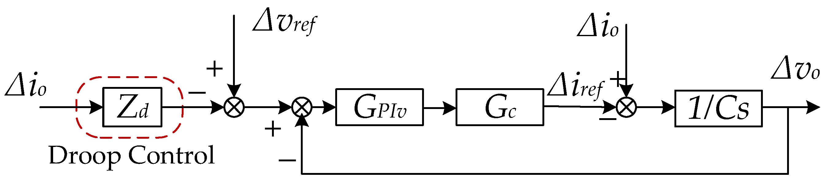
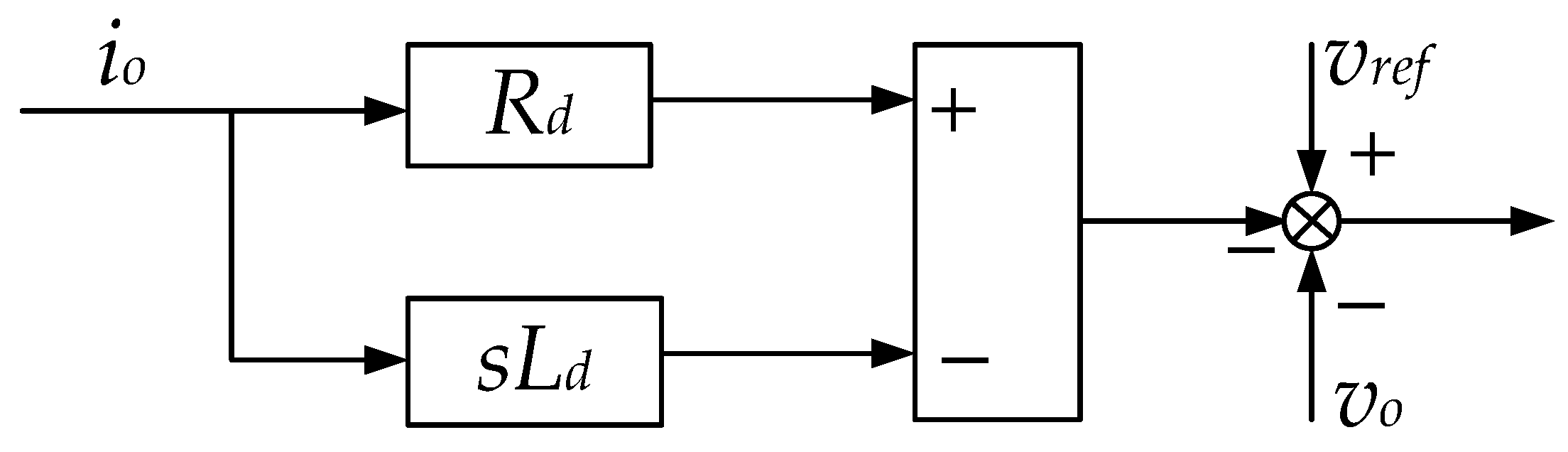
3.2. Virtual Inductance Control Strategy

Voltage and current double closed-loop control is a common control method [12,18]. And transfer function of voltage and current double closed-loop control of DC microgrid given by
G C L i ( s ) = ( k p i s + k i i ) V 0 L s 2 + k p i V 0 s + k i i V 0 ,
G C L v ( s ) = ( k p v s + k i v ) ( 1 D ) C s 2 + k p v ( 1 D ) s + k i v ( s ) ,
k p i , k i i are the proportional and integral parameters of current loop, respectively. And k p v , k i v are the proportional and integral parameters of voltage loop, respectively. According to the selection rules of controller parameters in [16], the specific PI controller parameters of this paper given in Table 1. The dynamic characteristics of the current inner loop can be equivalent to proportional gain one when calculating the voltage outer loop transfer function. The small signal block diagram of the droop control strategy can be derived, as illustrated in Figure 5 [28].
Figure 5. Small signal control block diagram of droop control.
Applsci 09 04449 g005
where Z d is the droop control, Δ v o ,   Δ v r e f   ,   Δ i o ,   Δ i r e f are the perturbation of the output voltage, the reference voltage, output current, and the output reference current of double closed-loop controller, respectively. G P I v ( s ) is the voltage control loop transfer function and G c ( s ) is the current inner loop controller closed-loop transfer function. The output voltage perturbation Δ v o can be given by:
Δ v o   = G P I v ( S ) G c ( s ) C s + G P I v ( s ) G C ( s ) Δ v r e f - 1 + Z d G P I v ( s ) G c ( s ) C s + G P I v ( s ) G c ( s ) Δ i o ,
In (15), the change of Δ v r e f and Δ i 0 have an effect on the bus voltage. It is generally considered that the reference voltage of the system is unique and the fluctuation of the output voltage is determined by the change of the output current. Therefore, reasonable design of control strategy can reduce the influence of the latter. The definition is as follows
1 + Z d G P I v ( s ) G c ( s ) = 0 ,
And Z d can be rewritten as
Z d = L d s 1 T s + 1 ,
where Ld = 1/kiv, and T = kpv/kiv. Formula (18) can be considered as a form of multiplication of a coefficient L d differential link with a low-pass filter. According to the actual situation, the value of L d is chosen as shown in Table 1. On the basis of the traditional droop control, the control form is expressed as follows
Z d = R d L d s ,
And an improved droop controller block diagram is depicted in Figure 6.
As shown in Figure 7, with the proposed control strategy, an equivalent virtual control link is added between the source and the transmission line, which is equivalent to a negative inductance link in the system, helps to offset the influence of the line inductance in the system.
The control parameters of system are shown in Table 1. Where the value of droop coefficient depends on the maximum voltage deviation Δ v 0 m a x and the rated output current i 0 . The maximum allowable voltage deviation is ±5% of the rated bus voltage. R d can be derived as:
R d = Δ v 0 m a x i 0 ,

4. Simulation Verification

In this section, simulation results in Matlab/Simulink are shown to validate the proposed control strategy. The changes in bus voltage, inductor current, and output current of the DC microgrid before and after the application of the control strategy are shown in Figure 8. Initially, the traditional droop control was applied. Due to the influence of CPLs, the system suffers oscillation. At t = 0.5s, the control strategy is switched from the traditional droop control to the proposed control strategy. Obviously, the DC microgrid bus voltage can quickly be restored to a stable state. Compared with the virtual capacitance control strategy based on droop control (the gray curve in the figure) in [18], the proposed control strategy in this paper can reduce the adjustment time and make the system reach the balance faster. In addition, the control strategy can reduce the bus voltage fluctuation during the regulation process. Overall, this strategy will have more advantages in improving stability. To further verify the effectiveness of the proposed strategy, the following tests are carried out with the change of droop coefficients, line lengths, and operating points.

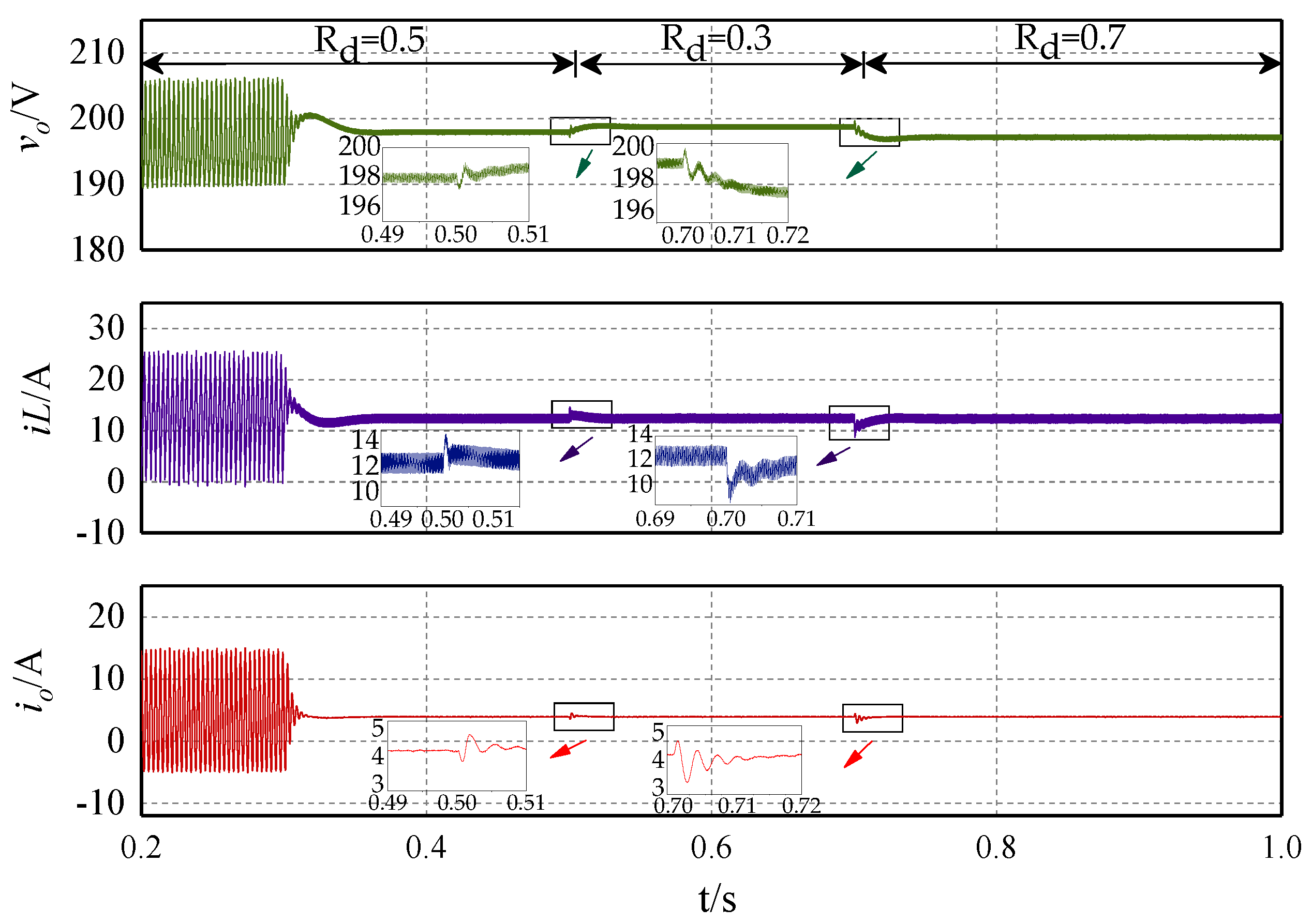
4.1. Change of Droop Coefficients

DC microgrids can coordinate the output of resources by adjusting the droop coefficient, which means that the system may operate under different droop coefficients due to different requirements [29]. Therefore, the stable operation of the system under different droop coefficients must be ensured. Figure 9 shows the simulation result of the proposed control strategy under different droop coefficients. It can be seen that the system remained stable whether the droop coefficient was switched to 0.3 or 0.7. Thus, it is evident that the control strategy can ensure the system stability under different droop coefficients.

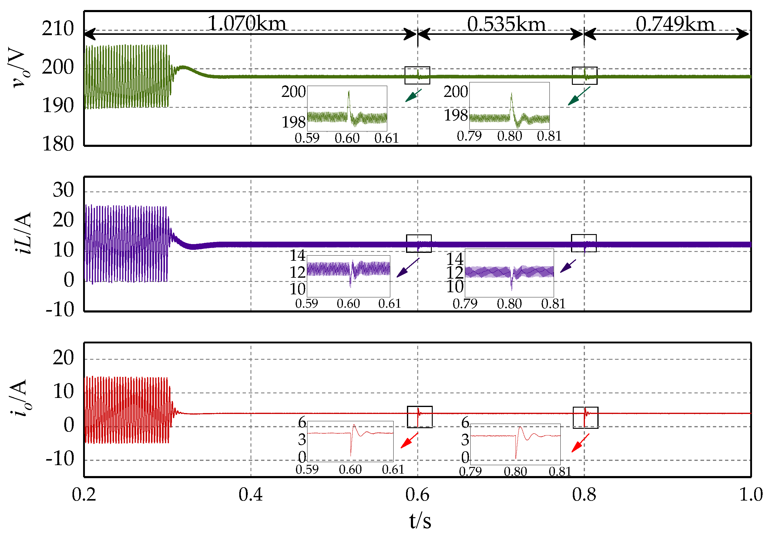
4.2. Change of Line Lengths

The system needs to meet the energy requirements of the load, but the distance between different loads and the bus are different. It is generally considered that the value of the droop coefficient is much larger than the line resistance and only the inductive component in the line is considered in this paper. The inductance of the line is proportional to the length. Hence, the variable considered in this section is the line length. As shown in Figure 10, the line length varies following the sequence of 1.070 km, 0.535 km and 0.749 km. It can be seen that no matter the length of the line increases or decreases, the DC microgrid can keep stable after applying the proposed control strategy. Thus, the effectiveness of the proposed stabilization strategy is proved when the system line length varies.

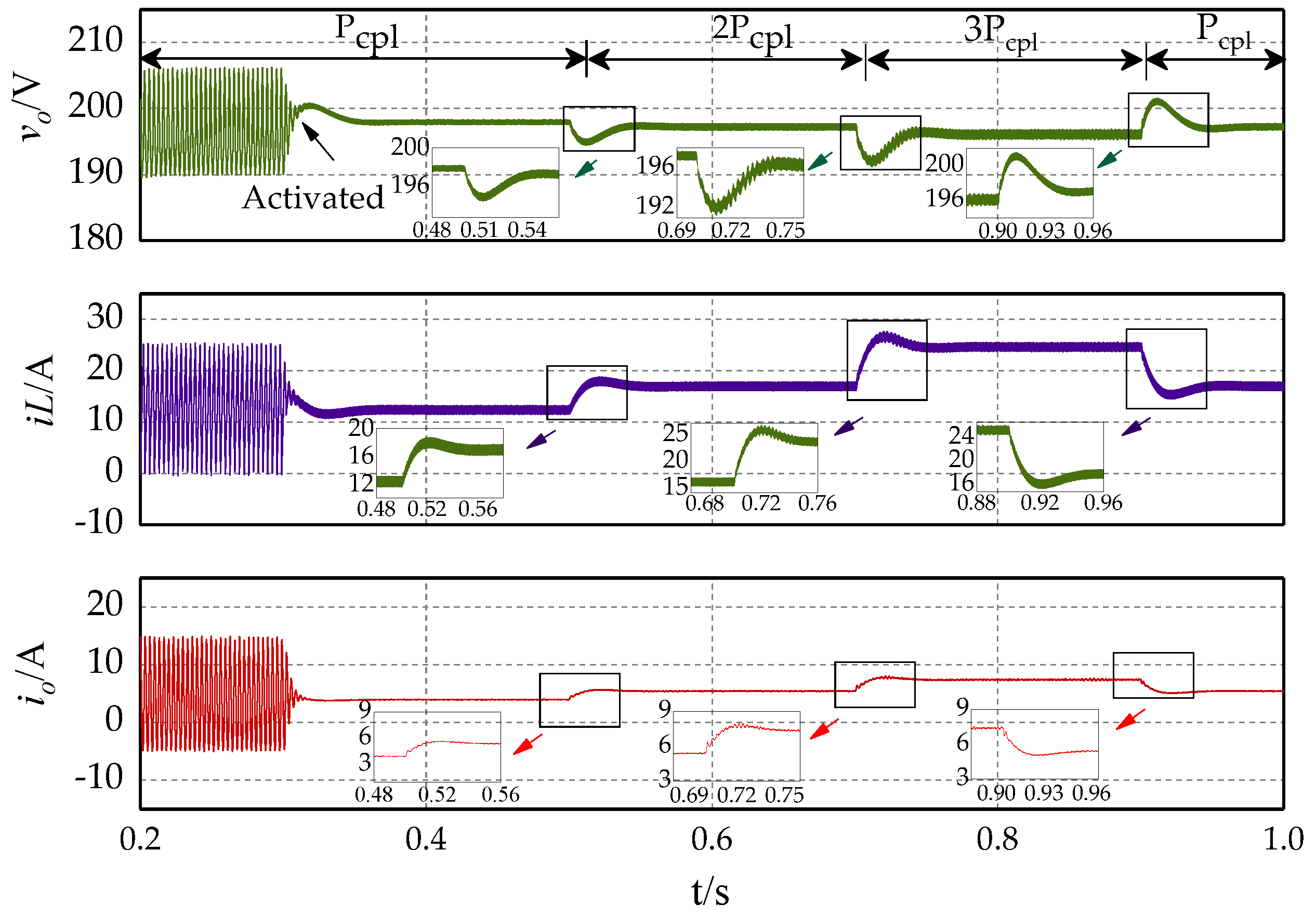
4.3. Change of Operating Points

The load in the DC microgrid is an important part of the system and one of the main factors affecting the stability of the system. Instability problems are more likely to occur when load changes [30,31]. Thus, the effectiveness of the proposed control strategy was verified by changing the power of CPLs. The load doubled at 0.5 s, tripled at 0.7 s, and recovered to the initial at 0.9 s, as illustrated in Figure 11. It can be seen that the system operates steadily whether the power increases or decreases. It proves that the control strategy can improve the system robustness in case of load variation.

5. Conclusions

A virtual negative inductance control strategy for DC microgrids with constant power loads is proposed in this paper. The particular is that this strategy improves the stability of the system from the point of line inductance. And the main contributions of this paper lie in the following:
(1)
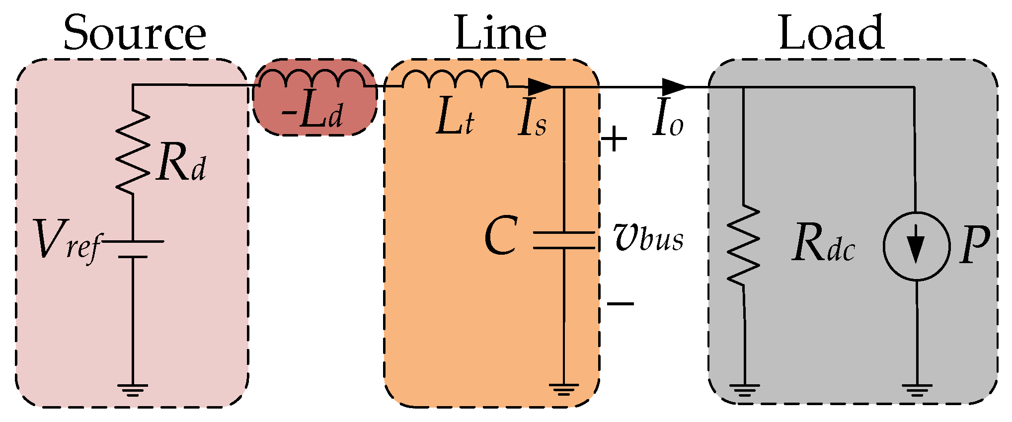
Complex multi-dimensional DC microgrid systems are not conducive to analysis. So, a concise system model was obtained by simplifying the distributed generation model and the multi-branch model. Moreover, the model takes into account multiple types of power supply and loads in a DC microgrid system, which is closer to the actual situation.
(2)
The instability caused by constant power loads can be attributed to the change of output current Δi0. The expression of the control strategy in this paper was deduced to solve the problem of current effect. And the form of control strategy was equivalent to adding a negative inductance link to the system model.
(3)
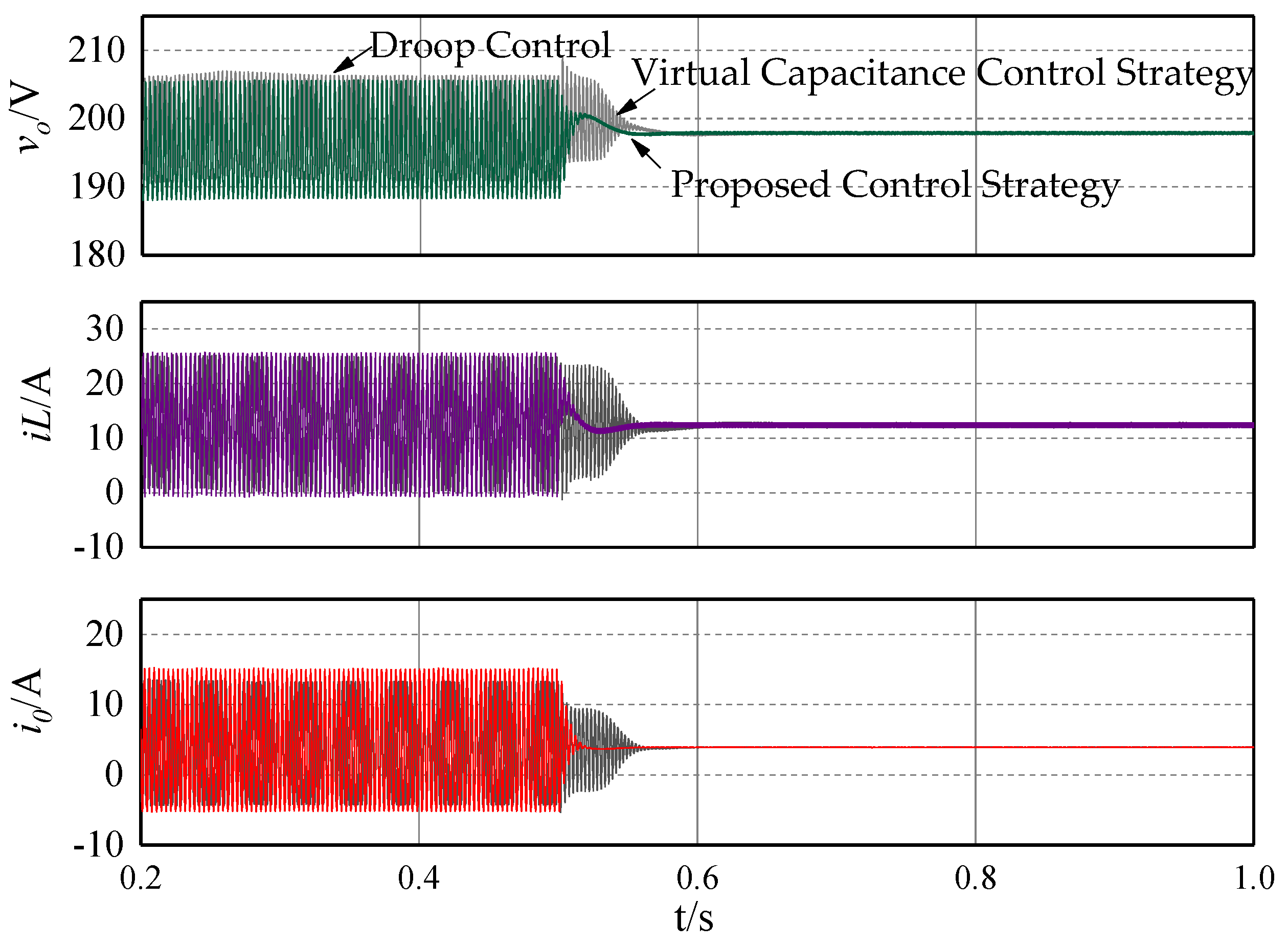
The effectiveness of this strategy was verified and compared with the existing virtual capacitance control strategy. The results show that this strategy can effectively solve the instability of DC microgrid. It also proves that the proposed strategy has faster and smoother regulation process when compared with the virtual capacitance strategy.
In this paper, the stability of a single DC microgrid is studied. For future work, the stability of a DC microgrid group will be of concern. The power generation variation of renewable energy based distributed generators will also be considered. And more detailed research will be carried out by considering more detailed transient models of distributed generation and load. Besides, we also intend to extend the proposed control strategy to a hybrid alternating current (AC)/DC microgrid.

Author Contributions

Conceptualization, Z.C. and M.G.; methodology, G.M. and Z.L.; software, Z.C., M.G. and Z.L.; validation, Z.C. and M.G. and J.G.; formal analysis, Z.C. and M.G.; investigation, M.G.; resources, Z.L.; data curation, J.G.; writing—original draft preparation, M.G.; writing—review and editing, Z.C. and M.G.; visualization, Z.C. and M.G.; supervision, J.G., Z.L. and J.S.; project administration, Z.L.; and funding acquisition, M.G.

Funding

This work was supported by the National Natural Science Foundation of China (61803343), the China Postdoctoral Science Foundation (2018M630835), and the Key Projects of Higher Education of Henan Province (18A470015,18A470017, and 19A120012).

Conflicts of Interest

The authors declare no conflict of interest.

Abbreviations

The following abbreviations are used in the manuscript:
DCDirect Current
ACAlternating Current
CPLsConstant Power Loads
CPSsConstant Power Sources
MPPTMaximum Power Point Tracking
PVPhotovoltaic

References

  1. Bayati, N.; Hajizadeh, A.; Soltani, M. Protection in DC microgrids: A comparative review. IET Smart Grid 2018, 1, 66–67. [Google Scholar] [CrossRef]
  2. Naderi, Y.; Hosseini, S.H.; Ghassem Zadeh, S.; Mohammadi-Ivatloo, B.; Vasquez, J.C.; Guerrero, J.M. An overview of power quality enhancement techniques applied to distributed generation in electrical distribution networks. Renew. Sustain. Energy Rev. 2018, 93, 201–214. [Google Scholar] [CrossRef] [Green Version]
  3. Kamel, R.M.; Chaouachi, A.; Nagasaka, K. Detailed Analysis of Micro-Grid Stability during Islanding Mode under Different Load Conditions. Engineering 2011, 3, 508–516. [Google Scholar] [CrossRef]
  4. Shivam; Dahiya, R. Stability analysis of islanded DC microgrid for the proposed distributed control strategy with constant power loads. Comput. Electr. Eng. 2018, 70, 151–162. [Google Scholar] [CrossRef]
  5. Tahim, A.P.N.; Pagano, D.J.; Lenz, E.; Stramosk, V. Modeling and Stability Analysis of Islanded DC Microgrids Under Droop Control. IEEE Trans. Power Electron. 2015, 30, 4597–4607. [Google Scholar] [CrossRef]
  6. Su, M.; Liu, Z.; Sun, Y.; Han, H.; Hou, X. Stability Analysis and Stabilization Methods of DC Microgrid with Multiple Parallel-Connected DC–DC Converters Loaded by CPLs. IEEE Trans. Smart Grid 2018, 9, 132–142. [Google Scholar] [CrossRef]
  7. Pakdeeto, J.; Areerak, K.; Areerak, K. Large-signal model of DC micro-grid systems feeding a constant power load. In Proceedings of the 2017 International Electrical Engineering Congress (iEECON), Pattaya, Thailand, 8–10 March 2017; pp. 1–4. [Google Scholar]
  8. Liu, Z.; Su, M.; Sun, Y.; Han, H.; Hou, X.; Guerrero, J.M. Stability analysis of DC microgrids with constant power load under distributed control methods. Automatica 2018, 90, 62–72. [Google Scholar] [CrossRef] [Green Version]
  9. Cespedes, M.; Xing, L.; Sun, J. Constant-Power Load System Stabilization by Passive Damping. IEEE Trans. Power Electron. 2011, 26, 1832–1836. [Google Scholar] [CrossRef]
  10. Céspedes, M.; Beechner, T.; Xing, L.; Sun, J. Stabilization of constant-power loads by passive impedance damping. In Proceedings of the 2010 Twenty-Fifth Annual IEEE Applied Power Electronics Conference and Exposition (APEC), Palm Springs, CA, USA, 21–25 February 2010; pp. 2174–2180. [Google Scholar]
  11. Mayo-Maldonado, J.C.; Rapisarda, P. A systematic approach to constant power load stabilization by passive damping. In Proceedings of the IEEE Conference on Decision and Control, Osaka, Japan, 15–18 December 2015; pp. 1346–1351. [Google Scholar]
  12. Kim, H.-J.; Lee, Y.-S.; Kim, J.-H.; Han, B.-M. Coordinated droop control for stand-alone DC micro-grid. J. Electr. Eng. Technol. 2014, 9, 1072–1079. [Google Scholar] [CrossRef]
  13. Ko, B.-S.; Lee, G.-Y.; Choi, K.-Y.; Kim, R.-Y. A Coordinated Droop Control Method Using a Virtual Voltage Axis for Power Management and Voltage Restoration of DC Microgrids. IEEE Trans. Ind. Electron. 2019, 66, 9076–9085. [Google Scholar] [CrossRef]
  14. Cheng, Z.; Li, Z.; Liang, J.; Gao, J.; Si, J.; Li, S. Distributed Economic Power Dispatch and Bus Voltage Control for Droop-Controlled DC Microgrids. Energies 2019, 12, 1400. [Google Scholar] [CrossRef]
  15. Lu, X.; Guerrero, J.M.; Sun, K.; Vasquez, J.C. An Improved Droop Control Method for DC Microgrids Based on Low Bandwidth Communication with DC Bus Voltage Restoration and Enhanced Current Sharing Accuracy. IEEE Trans. Power Electron. 2014, 29, 1800–1812. [Google Scholar] [CrossRef]
  16. Guo, L.; Zhang, S.; Li, X.; Li, Y.W.; Wang, C.; Feng, Y. Stability Analysis and Damping Enhancement Based on Frequency-Dependent Virtual Impedance for DC Microgrids. IEEE J. Emerg. Sel. Top. Power Electron. 2017, 5, 338–350. [Google Scholar] [CrossRef]
  17. Wu, W.; Chen, Y.; Zhou, L.; Zhou, X.; Yang, L.; Dong, Y.; Xie, Z.; Luo, A. A Virtual Phase-Lead Impedance Stability Control Strategy for the Maritime VSC–HVDC System. IEEE Trans. Ind. Inform. 2018, 14, 5475–5486. [Google Scholar] [CrossRef]
  18. Zhu, X.; Xie, Z.; Jing, S.; Ren, H. Distributed virtual inertia control and stability analysis of dc microgrid. IET Gener. Transm. Distrib. 2018, 12, 3477–3486. [Google Scholar] [CrossRef]
  19. Hosseinipour, A.; Hojabri, H. Virtual inertia control of PV systems for dynamic performance and damping enhancement of DC microgrids with constant power loads. IET Renew. Power Gener. 2018, 12, 430–438. [Google Scholar] [CrossRef]
  20. Huangfu, Y.; Pang, S.; Nahid-Mobarakeh, B.; Guo, L.; Rathore, A.K.; Gao, F. Stability Analysis and Active Stabilization of On-board DC Power Converter System with Input Filter. IEEE Trans. Ind. Electron. 2018, 65, 790–799. [Google Scholar] [CrossRef]
  21. Anand, S.; Fernandes, B.G. Reduced-Order Model and Stability Analysis of Low-Voltage DC Microgrid. IEEE Trans. Ind. Electron. 2013, 60, 5040–5049. [Google Scholar] [CrossRef]
  22. Tah, A.; Das, D. Analysis on different aspects of interconnected DC microgrids. In Proceedings of the 2016 IEEE International Conference on Power Electronics, Drives and Energy Systems (PEDES), Trivandrum, India, 14–17 December 2016; pp. 1–6. [Google Scholar]
  23. Gunasekaran, M.; Ismail, H.M.; Chokkalingam, B.; Mihet-Popa, L.; Padmanaban, S. Energy Management Strategy for Rural Communities’ DC Micro Grid Power System Structure with Maximum Penetration of Renewable Energy Sources. Appl. Sci. 2018, 8, 585. [Google Scholar] [CrossRef]
  24. Marcon, P.; Szabo, Z.; Vesely, I.; Zezulka, F.; Sajdl, O.; Roubal, Z.; Dohnal, P. A Real Model of a Micro-Grid to Improve Network Stability. Appl. Sci. 2017, 7, 757. [Google Scholar] [CrossRef]
  25. Xu, L.; Chen, D. Control and Operation of a DC Microgrid with Variable Generation and Energy Storage. IEEE Trans. Power Deliv. 2011, 26, 2513–2522. [Google Scholar] [CrossRef]
  26. Wei, Y.; Luo, Q.; Chen, S.; Huang, J.; Zhou, L. DC current bus distributed power system and its stability analysis. IET Power Electron. 2019, 12, 458–464. [Google Scholar] [CrossRef]
  27. Chang, Y.C.; Chang, H.C.; Huang, C.Y. Design and Implementation of the Battery Energy Storage System in DC Micro-Grid Systems. Energies 2018, 11, 1566. [Google Scholar] [CrossRef]
  28. Li, Y.; Fan, L. Stability Analysis of Two Parallel Converters with Voltage–Current Droop Control. IEEE Trans. Power Deliv. 2017, 32, 2389–2397. [Google Scholar] [CrossRef]
  29. Mokhtar, M.; Marei, M.I.; El-Sattar, A.A. An Adaptive Droop Control Scheme for DC Microgrids Integrating Sliding Mode Voltage and Current Controlled Boost Converters. IEEE Trans. Smart Grid 2019, 10, 1685–1693. [Google Scholar] [CrossRef]
  30. Moussa, S.; Ghorbal, M.J.; Slama-Belkhodja, I.; Martin, J.; Pierfederici, S. DC bus voltage instability detection and stabilization under constant power load variation. In Proceedings of the 2018 9th International Renewable Energy Congress (IREC), Hammamet, Tunisia, 20–22 March 2018; pp. 1–6. [Google Scholar]
  31. Xiao, B.; Dai, D.; Zhang, B.; Han, Y. Bifurcation and its analysis of DC Micro-Grid under abrupt load change. J. Electr. Eng. 2016, 31, 131–141. [Google Scholar]
Figure 1. Typical configuration of an island direct current (DC) micro grid.
Applsci 09 04449 g001
Figure 2. Distributed Resources model. (a) Maximum Power Point Tracking (MPPT) control. (b) Droop control.
Applsci 09 04449 g002
Figure 3. Multi-branch combination model of n droop control resources.
Applsci 09 04449 g003
Figure 6. Improved droop controller.
Applsci 09 04449 g006
Figure 7. Virtual negative inductive reactance control strategy.
Applsci 09 04449 g007
Figure 8. Simulation results of a DC microgrid system with the proposed control strategy.
Applsci 09 04449 g008
Figure 9. Simulation results of DC microgrid system with the change droop coefficient.
Applsci 09 04449 g009
Figure 10. Simulation results of DC microgrid system with the change of line length.
Applsci 09 04449 g010
Figure 11. Simulation results of a DC microgrid system with the change of operation points.
Applsci 09 04449 g011
Table 1. Parameters of DC microgrid system.
ParameterMagnitude
Input Voltage V S 100 v
Bus Voltage V b u s 200 v
Filter Inductor L / R 13.68 mH/0.4Ω
Bus Capacitance C 840 μF
Switching frequency f s 10 kHz
Droop coefficient R d 0.5
Resistive load R d c 100 Ω
Line inductor L t 0.5 mH
Proportional Coefficient of Current Controller k p i 0.5
Integral Coefficient of Current Controller k i i 100
Proportional Coefficient of Voltage Controller k p v 1.2
Integral Coefficient of Voltage Controller k i v 250
Filter Coefficient T 0.0005
Droop Coefficient R d 0.5
virtual inductive L d 5

