1. Introduction
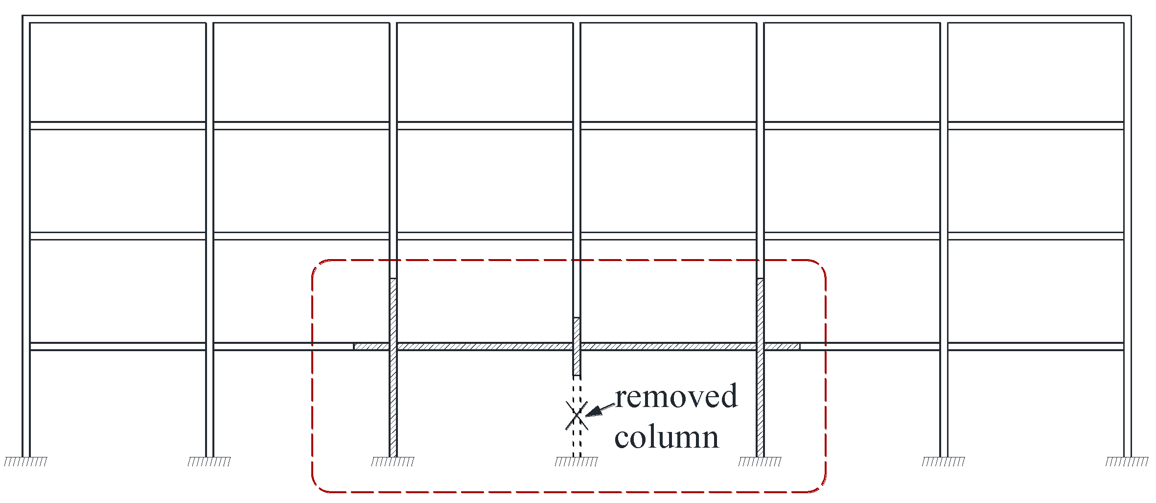
Reinforced concrete (RC) frame structures are widely used in building engineering, unexpected failure of one or several columns due to explosion or vehicle impact is most likely to lead to the disproportionate collapse of frames, which might cause catastrophic consequences. After the terrorist attacks of the world trade building in 2001, more attention was paid on progressive collapse of buildings and many research works had been conducted in the followed several decades. Izzuddin et al. [
1] proposed a simplified framework for progressive collapse assessment of multi-storey buildings in the scenario of sudden column loss. Yu et al. [
2] experimentally investigated the progressive collapse resistance of RC beam-column sub-assemblages under a middle column removal scenario, tests results validated that both compressive arch action and catenary action can significantly enhance the structural resistance. Kazemi et al. [
3] developed an analytical model of the structure accounting for the interaction between the axial and flexural deformations and discussed the main progressive collapse resisting mechanism. Lu et al. [
4] tested on five 1/3-scaled RC frame substructures and investigated the effect of critical structural parameters on the collapse resistance, the experimental results showed that the resistance of the beam-slab specimens were mainly provided by the slabs and the beams in the direction along the free edge. Al-Salloum et al. [
5] experimentally studied the effectiveness of using bolted steel plates on the behavior of precast beam-column connections under sudden column-loss scenario, the effect of different steel plates parameters on the response of test frames was also simulated. Almusallam et al. [
6] experimentally evaluated the influence of two types of detailing of precast beam-column joints on the structural collapse after a middle column was removed suddenly, and the test results helped in developing better understanding about the progressive collapse of the existing precast buildings. Ameri et al. [
7] highlight the importance of considering structural redundancy effects on progressive collapse of RC frame buildings. Qian et al. [
8] carried out tests on posttensioned concrete beam-column sub-assemblages with unbonded posttensioning strands, the collapse modes and mechanisms were investigated.
In recent years, concrete frame structures reinforced with fiber reinforced polymer (FRP) are gradually applied in building engineering, especially in coastal engineering structures due to excellent durability, light weight, as well as high ultimate strength of FRP. Therefore, mechanical performance of FRP materials and structural members reinforced with FRP have been widely studied. Robert et al. [
9] investigated the physical, mechanical, and durable characterization of glass fiber-reinforced polymer (GFRP) bars subjected to different tensile stress levels. Spagnuolo et al. [
10] experimentally studied the residual behavior of GFRP bars subjected to different temperatures treatments, it was found that improvements in polymer matrix of GFRP bars helped to improve their performance after high temperature exposure, and it is important to minimize the moisture inside the composite to avoid the premature failure of the fibers under high temperatures. Mazzotti et al. [
11] carried out tests on specimens with different bonded lengths and plate widths to investigate FRP-concrete delamination, and the effect of plate width on main parameters of interface law was also studied. Donnini et al. [
12] experimentally investigated the effectiveness of three different strengthening techniques, including strengthening existing concrete elements with FRP, Fiber Reinforced Cementitious Matrix (FRCM) or High Performance Mortar (HPM) systems, and the main differences in terms of structural response were discussed. Imperatore et al. [
13,
14] experimentally and numerically studied the behavior of two RC T-beams strengthened in shear with CFRP, it showed that the shear strengthening of RC beams by externally bonded with FRP sheets is effectively improved.
Basalt fiber reinforced polymer (BFRP) has been increasingly used in building structures due to its better cost-effectiveness, high ultimate strengthen, and light weight. Mechanical performance of BFRP and structural members reinforced with BFRP were widely studied in recent several decades. Monaldo et al. [
15] reviewed the art concerning BFRP and affirmed the merits of BFRP. Nerilli et al. [
16] experimentally investigated the debonding failure mode of BFRP reinforcements from concrete supports, and the influence of composite thickness, width ratio between the BFRP width and the concrete one, anchor length, on the debonding load was discussed. Tomlinson et al. [
17] evaluated the flexure and shear performance of concrete beams reinforced with BFRP bars and stirrups. Abed et al. [
18] experimentally investigated the effects of adding different types of fibers to the concrete mixes on the flexural behavior of concrete beams reinforced longitudinally with BFRP bars, it showed that introducing basalt fibers to the concrete increased curvature ductility of the beams and improved the flexural capacities. Abed et al. [
19] investigated the shear performance of deep concrete beams reinforced with BFRP bars without web reinforcement, and the influence of parameters including the effective depth and the longitudinal reinforcement ratio on the shear capacity of the beams was studied. Wang et al. [
20] investigated the degradation of the tension-tension fatigue behavior of BFRP composites after exposure to a salt solution, the results showed that the static strength of the BFRP hardly degenerated after aging in the salt solution, whereas the detrimental effect of saltwater became apparent under fatigue loading. Ma et al. [
21] proposed a hybridized basalt FRP and steel (BFRP-steel) rebar to overcome the limitation of high initial cost, low elastic modulus, and brittleness of BFRP bars. Based on the existing research literature, when concrete frame structures are reinforced with BFRP bars, they will be more vulnerable to collapse than common RC structures due to weak stiffness of structural members in the scenario of load-bearing columns loss. Collapse performance of concrete structures retrofitted with carbon FRP and glass FRP has been investigated in recent years [
22,
23]. However, little research is done on the progressive collapse of concrete frames reinforced with BFRP bars. In view of the existing problems, collapse tests, including dynamic collapse tests and static collapse tests, were conducted on six beam-column frame sub-assemblages reinforced with BFRP bars in the beams, and collapse responses, as well as collapse patterns of the sub-assemblages, were discussed. This paper mainly reports the research results of the static collapse tests.
3. Experimental Results of Static Collapse Tests
3.1. Loading Process
In the dynamic collapse tests, temporary supports under the middle column were removed by striking. Then the residual sub-assemblages began to vibrate due to the action of steel weight. The stiffness of the sub-assemblages reinforced with BFRP bars in the beams was obviously lower because of the low elastic modulus of BFRP bars. A series of cracks appeared on the frame beams, which mainly concentrated at the beam ends. The residual vertical deformation of the frame beams was observed even after the steel weight was taken away. Then, static collapse tests were carried out by applying the monotonic static load on the top of the failed middle column. The main observed phenomena in the static collapse tests are as follows:
S1—Vertical displacement at the failed middle column kept rising with the applied load, several existing cracks at the beams ends appeared in the dynamic collapse tests extended along the beam height in the initial loading stage. When the vertical displacement at the failed middle column reached 68.2 mm at the load of 30.2 kN, the load-bearing resistance decreased fast due to local crushing of concrete at the beam ends near to the middle column (BEMCs). In the following loading process, the load-bearing resistance kept wave-like increasing tendency, every drop of load-bearing capacity was connected with severe cracking or crushing of concrete at the beam ends and partial fracture of BFRP bars. Concrete at both the BEMCs and the beam ends near to the side column (BESCs) crushed successively, the difference was that the compression damage regions at the BEMCs were much larger. When the applied load reached 71.0 kN, BFRP bars at one of the BESCs fractured completely and the frame beam fell off from the sub-assemblage.
S2—Many new cracks appeared at the BEMC in the initial loading stage. When the vertical displacement reached 64.8 mm, concrete at the top of the BEMCs locally crushed with the corresponding load of 32.2 kN. The load applied to the top of the middle column kept increasing with the vertical displacement. At the displacement of 290.0 mm, load-bearing capacity dropped rapidly due to the formation of major cracks at the BESCs and the development of crushed regions at the BEMCs. After that, the bearing capacity presented wave-like increasing tendency due to continuous structural damage. When the vertical displacement reached 496.0 mm, several bottom BFRP bars at the BEMCs fractured and then the loading process ended. During the loading process, the unbonded prestressing steel strand did not fracture until the end of the test.
S3—The loading procedure was similar to that of S2. The first peak load appeared at the displacement of 47.0 mm, with the associated load being 36.9 kN. Then concrete at the BEMCs and the BESCs crushed successively. When the vertical displacement at the failed middle column reached 370 mm, with the associated load being about 111.9 kN, the steel prestressing strand at one of the BESCs fractured and the test ended.
S4—When the vertical displacement reached 50.1 mm, concrete at the one of the BEMCs was partially crushed, which led to the transiently fast drop of the load. Then the load began to increase again with the vertical displacement. When the displacement was about 153.5 mm, with the corresponding load being 46.9 kN, crushed regions of concrete in the BEMCs further increased and the load dropped quickly. At the displacement of 247 mm, BFRP bars exposed in air due to concrete peeling off from the BESCs. When the vertical displacement reached 350 mm, BFRP bars fractured at the BESCs and the frame beams completely broke away from the sub-assemblage.
S5—Being different from S1, all reinforcement in the frame beams of S5, including stirrups, used BFRP bars. When the vertical displacement reached 50 mm, concrete cracked severely at the BESCs and was partially crushed at the BEMCs. When the displacement reached 100 mm, the associated load being about 34.2 kN, concrete in the compressive regions of the BEMCs crushed and peeled off seriously. The bearing capacity kept wave–like rising until the displacement reached 320 mm. At this time, the top BFRP bars in one of the BESCs fractured and led to the dramatic decrease of the load-bearing capacity.
S6—The observed phenomena were similar to S1. When the displacement increased to 133.4 mm, with the corresponding load being 25.0 kN, concrete at the BESCs cracked seriously and concrete at the BEMCs was partially crushed. When the displacement reached 357.3 mm, major cracks formed at the BESCs and BFRP bars were observed exposed in air due to concrete peeling off. Thereafter, concrete at the BEMCs crushed.
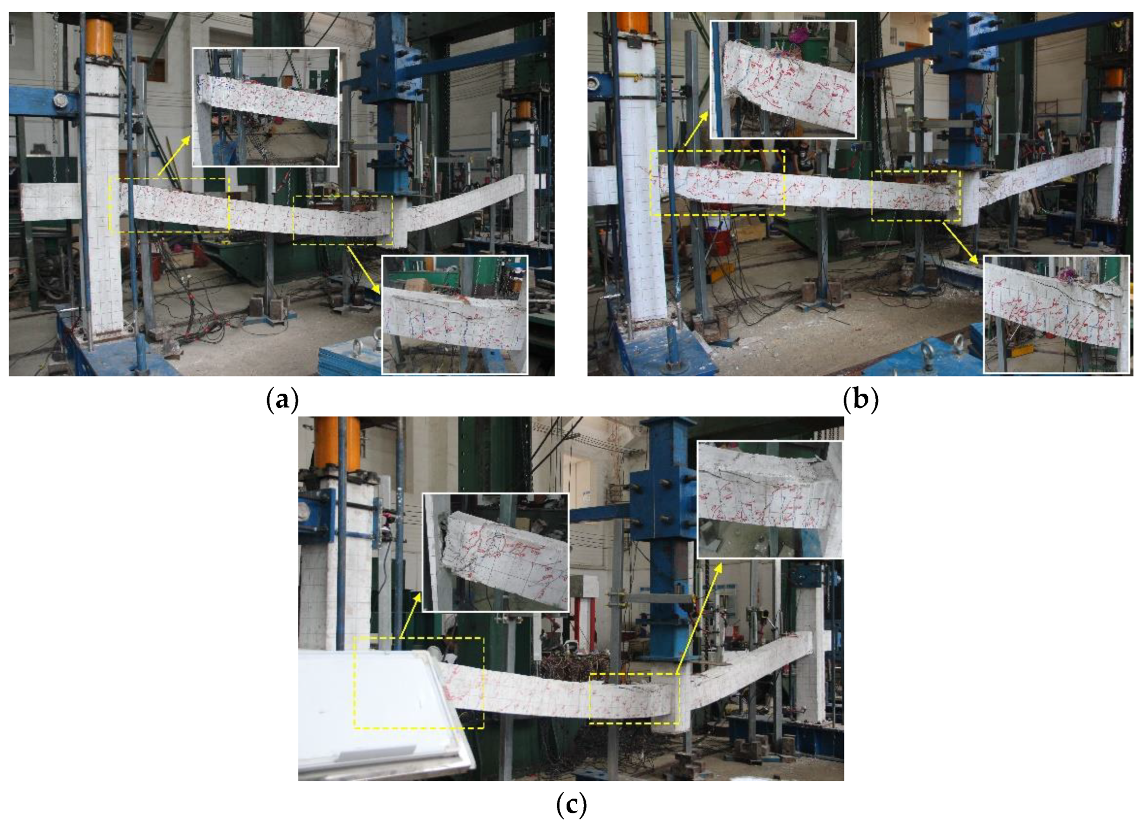
3.2. Failure Modes
Typical failure modes are shown in
Figure 6, taking S1, S3, as well as S5 as examples. In most cases, concrete at the top BEMCs and bottom BESCs was crushed successively, and the crushed regions at the BEMCs were usually larger than those at the BESCs. Cracks on the tested frame beams were commonly wider than that of common RC frame beams. Once BFRP bars fractured, the load bearing capacity dropped rapidly. The tested span to depth ratios of the frame beams had no significant influence on the failure modes of the sub-assemblages. Comparing S1 with S5 showed that, when steel stirrups in the frame beams were replaced by BFRP bars, the crushed regions at the BEMCs significantly increased. In addition, applying to prestress on the frame beams strengthened the initial stiffness of the beams. During the tests, only several cracks were observed at the foot of the side columns.
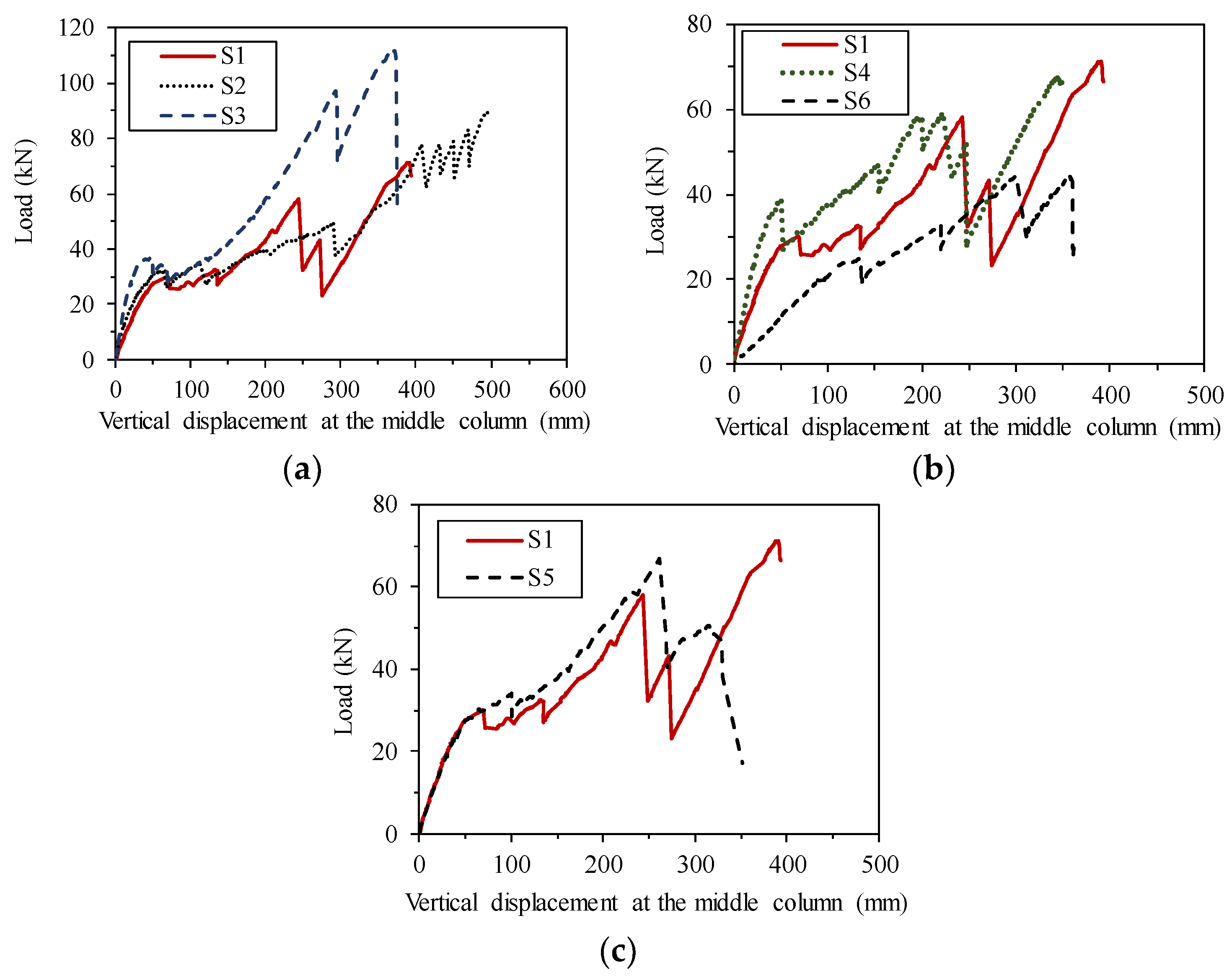
3.3. Relationship between Load and Vertical Displacement at the Failed Middle Column
Figure 7 illustrates the relationship between load and vertical displacement at the failed middle column. The characteristic load values of the sub-assemblages are listed in
Table 4. The comparison showed that: (1) The group of S1, S2, and S3 was used to investigate the influence of prestress on the collapse responses of the sub-assemblages reinforced with BFRP bars. Based on
Figure 7a, it is easy to find that S3, which was prestressed with bonded prestressing strand, possessed the highest initial stiffness, followed by S2 and S1 in turn. In the initial loading process, the vertical displacement at the middle column of the sub-assemblages almost increased linearly with the applied load. At the final failure stages, the maximum load-bearing capacity ranked in descending order was S3, S2, and S1, which indicated that the prestressing strand benefited to improve the ultimate resistance of the structures. In addition, integral stiffness of S2 was obviously weaker than S3, it should relate to the prestress loss after the failure of the middle column. (2) The group of S1, S4, and S6 was designed to investigate the influence of span to depth ratio of frame beams on the collapse resistance.
Figure 7b indicates that the smaller the span to depth ratio, the greater the integral stiffness of the sub-assemblages. In terms of ultimate load bearing capacity, S1 and S4 had a similar load bearing capacity, which was apparently higher than that of S6. (3) Comparing with S1, S5 possessed similar deformability and higher load-bearing capacity before final failure occurred. Therefore, it is feasible to replace steel stirrups of the frame beams by BFRP bars as an alternative without affecting the structural collapse resistance.
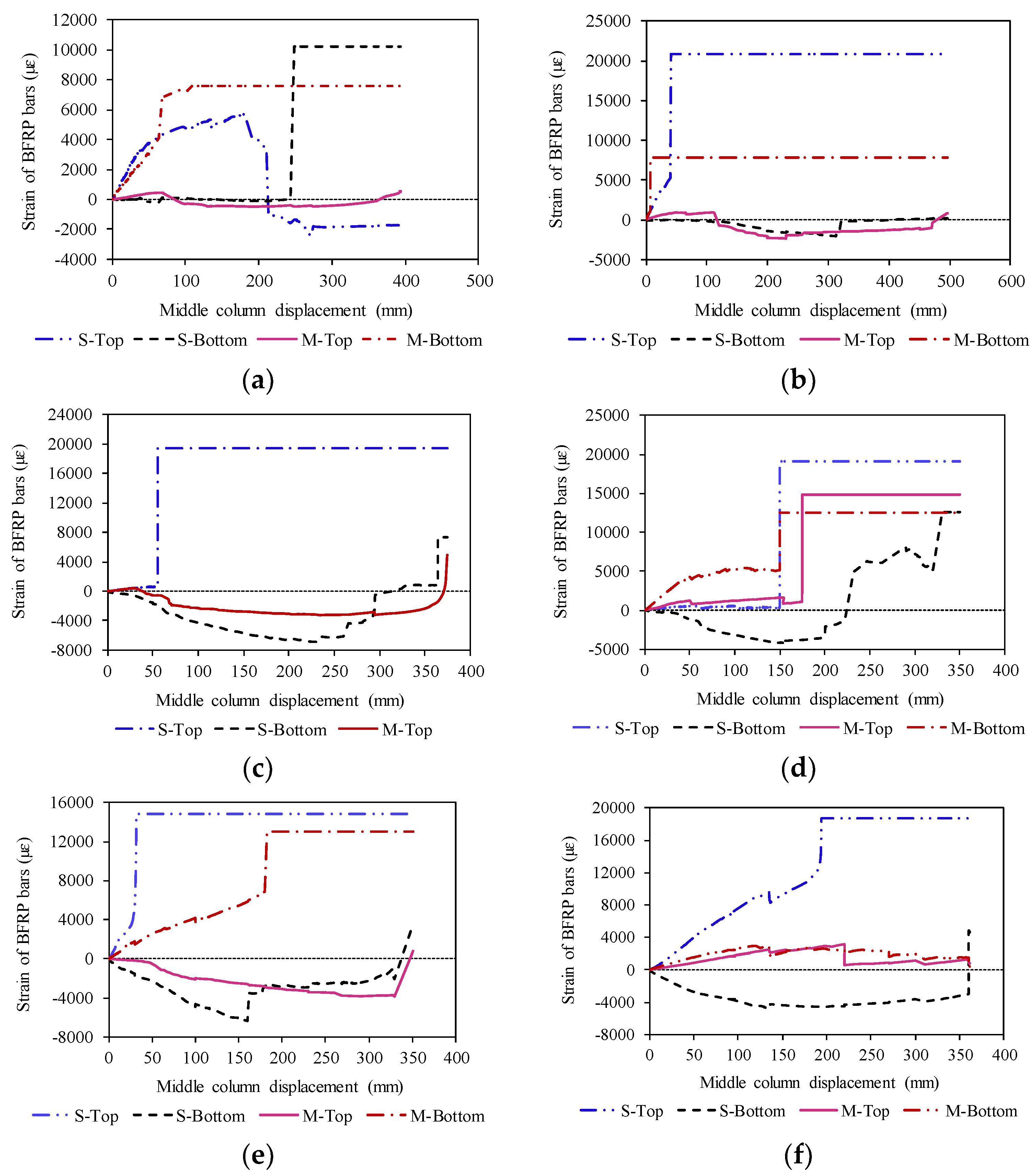
3.4. Strain Responses of BFRP Bars
The strain of BFRP bars was monitored during the tests as shown in
Figure 8, where S-Top and S-Bottom represent the top and bottom BFRP bars in the BESCs respectively, M-Top and M-Bottom mean the top and bottom BFRP bars in the BEMCs correspondingly. It can be seen that in most cases the S-Top and the M-Bottom BFRP bars kept tensile before the final failure occurred. While strain of the S-bottom and M-Top BFRP bars usually underwent fluctuation, commonly, they were firstly subjected to compression and then to tension. In general, the strain of the S-Bottom and M-Top BFRP bars was lower than that of the S-Top and the M-Bottom BFRP bars. It is noted that the strain of the S-Top and the M-Bottom BFRP bars increased fast in the early loading stages, this is related to the severe cracking of concrete at the beam ends due to low elastic modulus of BFRP bars.
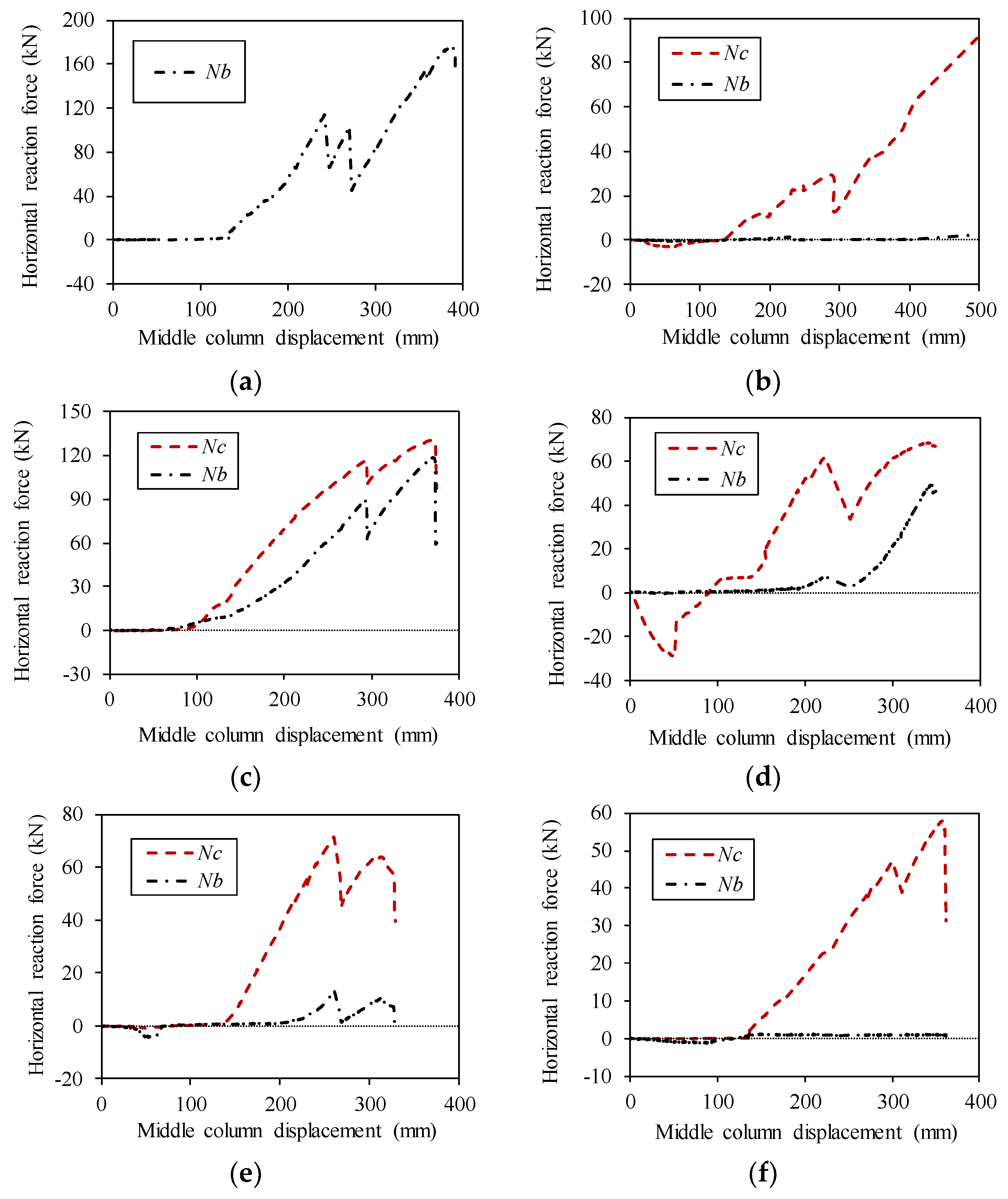
3.5. Horizontal Reaction Forces
Horizontal reaction forces could illustrate the effect of adjacent structures on the sub-assemblages.
Figure 9 shows the horizontal reaction forces versus vertical displacement curves, where
represents forces acting on the upper parts of the side columns, and
represents horizontal forces acting on the frame beam ends. It can be found both
and
are very small in the initial loading stage. However,
increased faster than
in the following loading process (
for S1 was not recorded due to the failure of the load cell). The horizontal reaction forces confined the free deformation of frame beams, which helped to mitigate the collapse risk of the residual sub-assemblages. As the upper parts of the side columns suffered great horizontal forces in this scenario, horizontal progressive collapse might happen once the upper adjacent columns had no enough shear resistance.
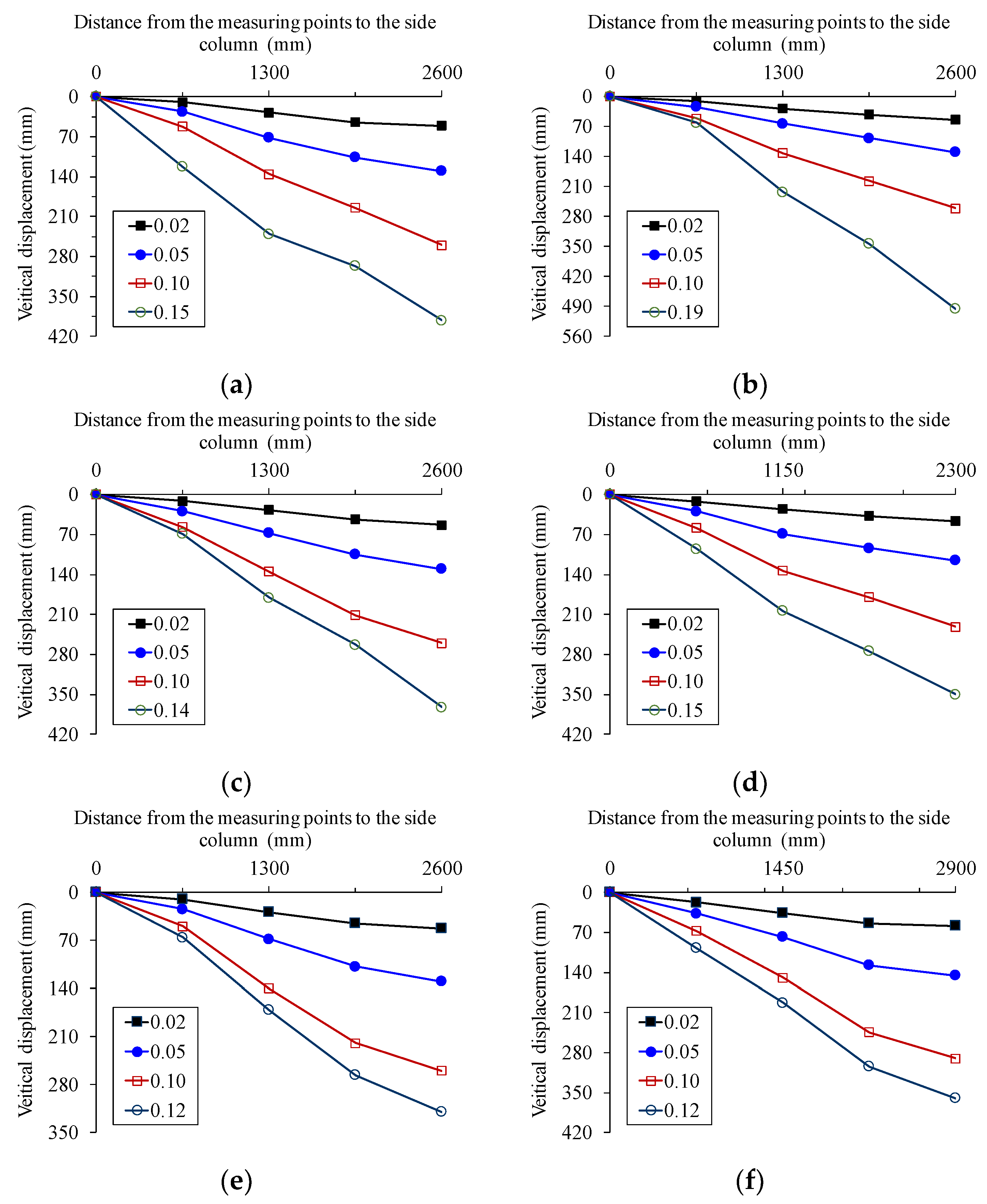
3.6. Overall Deformation of the Frame Beams
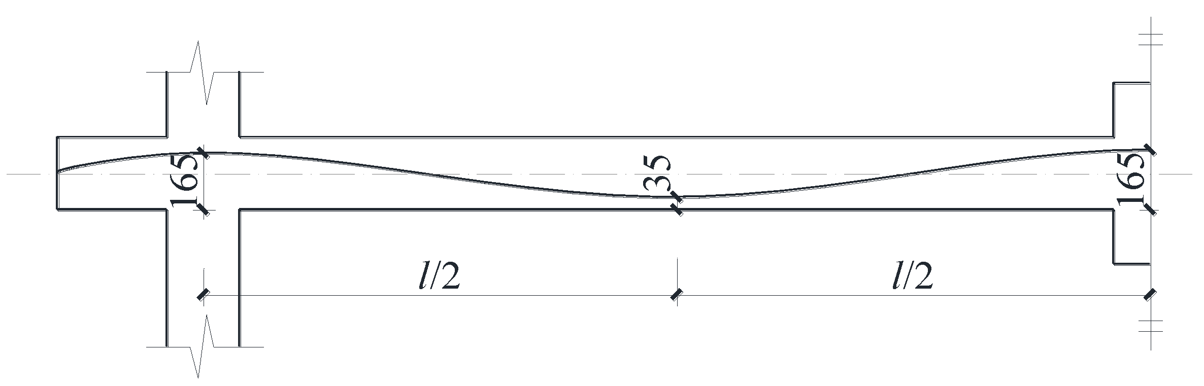
Vertical deformation of the frame beams under different load level was shown in
Figure 10, in which the four values in the legends were the ratios of the vertical displacement at the failed middle columns to the beam span, and the last value corresponded to the final failure stage. It was found that after the middle column failed, the deformation of the frame beams was nearly linear and proportional to the vertical displacement of the failed middle column. In addition, the ratios of the vertical displacement of the failed middle column at the final failure to the beam span varied from 0.12 to 0.19, which could provide a reference for the evaluation of the final failure of the frame structures reinforced with BFRP bars after the middle column loss.
3.7. Equivalent Dynamic Increase Factors of Collapse Load
Structural collapse actually is a dynamic process. Therefore, dynamic analysis is the most accurate method to assess the collapse responses of structures in the scenario of load-bearing members loss. However, researchers are most familiar with the static collapse analysis on the collapse behavior of structures. Dynamic increase factor (DIF) is usually used to take into account the dynamic effect of collapse load when static collapse analysis is conducted. As a result, taking proper DIF values in static collapse analysis becomes very important. A method based on energy conservation provided an effective method to determine DIF values of collapse load [
24]. As the method above is only suitable for the non-prestressed frame structures, the following is mainly to discuss the method to determine DIF values for prestressed frame structures.
As the prestressing strand in the frame beams was arranged in a parabolic shape, the pretension of the strand can be converted into segmentally distributed uniform loads along the beams by the load balance method proposed by Lin [
25]. It is assumed that the vertical displacement at any section of the frame beams was proportional to that of the failed middle column,
. Then, the work done by the equivalent uniform loads corresponding to
can be given by Equation (1):
where,
and
are the equivalent uniform loads of the initial pretension and the corresponding distribution lengths on the beam,
is the total number of the equivalent uniform load
,
is the vertical displacement at any section of the frame beams and proportionate to
according to the assumption,
is the coordinate of the beam section on the axis.
The initial prestressing is regarded as an external force here, so the total work,
, done by the external forces can be obtained by Equation (2):
where,
is a certain vertical displacement at the failed middle column under static load
,
is the load applied on the top of the middle column corresponding to
. Then, the corresponding equivalent dynamic load,
, at the vertical displacement of
can be got:
and the DIF value corresponding to
is
where,
is the equivalent load of initial pretension of the strand corresponding to
.
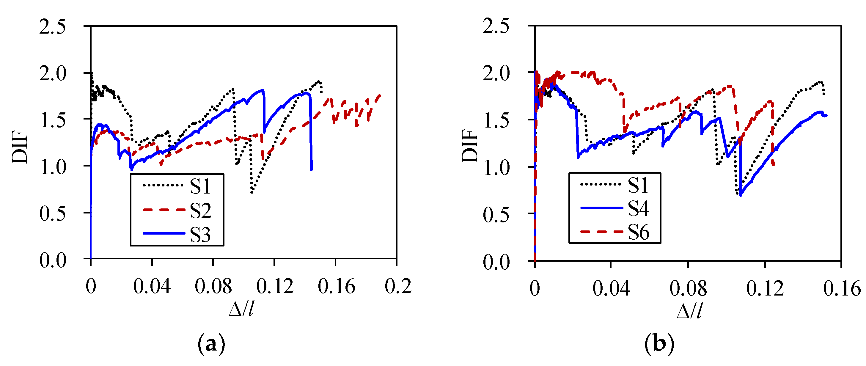
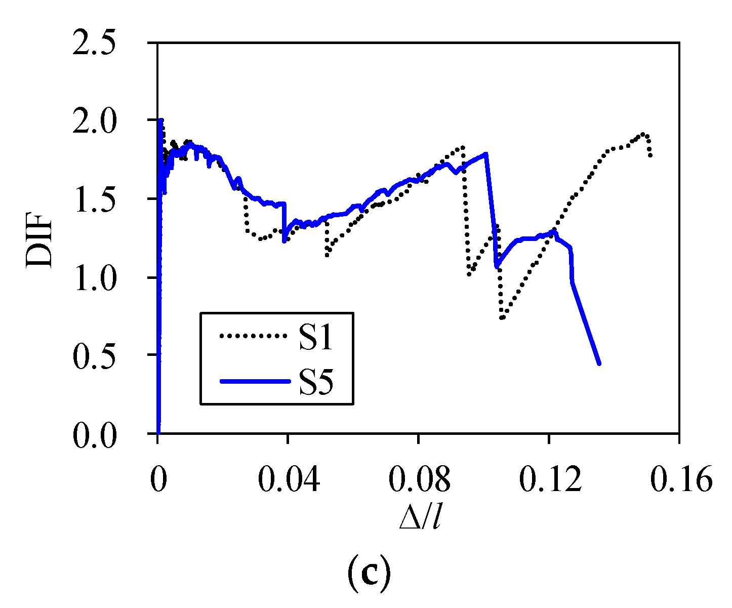
The curves of DIF values versus vertical displacement in the middle column are shown in
Figure 11. It can be seen that (1) the maximum DIF values of the sub-assemblages reinforced with BFRP bars in frame beams were close to 2.0 in the initial loading stage, while those for S2 and S3 were 1.38 and 1.44, respectively, due to the action of prestress. (2) In accordance with
Figure 11b, the specimen with greater span to depth ratio possessed higher DIF values. (3) From
Figure 11c, it can be seen that DIF values of the sub-assemblage were little affected during collapse when steel stirrups of the frame beams were replaced by BFRP bars. Based on the analysis above, it is suggested that the DIF values for the non-prestressed sub-assemblages should be conservatively taken as 2.0, while DIF values for the prestressed sub-assemblages could be taken between 1.44 and 2.0.
4. Conclusions
The following conclusions can be drawn based on the experimental investigation conducted in this research:
1. Experimental results showed that severe cracks mainly concentrated at the beam ends during the collapse. The initial stiffness of the frame beams reinforced with BFRP bars was obviously lower due to the low elastic modulus of BFRP bars. The collapse resistance presented wave-like increasing tendency with the vertical displacement at the failed middle column, which was significantly affected by structural damage, such as cracking or crushing of concrete and rupture of BFRP bars.
2. Top longitudinal BFRP bars at the BESC and bottom longitudinal BFRP bars at the BEMCs kept tensile during the loading process, which played an important role in resisting structural collapse. Adjacent structures could provide horizontal reaction forces to confine the free deformation of residual sub-assemblages after the middle column failed, and it was beneficial to mitigate the collapse risk of the frame structures. The vertical deformation of the frame beams beside the failed column was nearly linear and proportional to the vertical displacement of the failed middle column. Comparing with the sub-assemblage without prestress, unbonded prestress had negligible effect on the initial stiffness of the residual structures after the removal of the middle column. However, applying prestress could remarkably improve the collapse resistance of the structures.
3. DIF values of collapse load were discussed based on the energy conservation method, and a calculation method of DIF for prestressed frame structures was developed. It was suggested that DIF values for the non-prestressed frame structures reinforced with BFRP bars in the beams should be conservatively taken as 2.0, while those for the prestressed sub-assemblages can be taken between 1.44 and 2.0.


