1. Introduction
Take-up judder is a low frequency torsional rigid body dynamic response of the clutch system which is experienced by vehicle occupants during the clutch engagement at vehicle take-off. The frequency range is usually 5–20 Hz, leading to vehicle kangaroo-type fore and aft oscillations which are quite disconcerting [
1]. Maucher [
2] investigated the effect of frictional performance of the clutch lining material on the generated torsional vibrations. He concluded that friction-induced torsional vibrations of the clutch system appear with low drivetrain damping and particularly with a negative gradient for the coefficient of friction variation with clutch facing slip speed, whilst the clamp load, torsional stiffness and mass moment of inertia of the clutch showed slight effects. Bostwick et al. [
3] used a dedicated clutch dynamometer to investigate the self-excited vibrations during clutch engagement. They determined that judder arises due to the thermo-elastic distortion of contacting surfaces, or misalignments in the drivetrain, as well as a negative coefficient of friction of clutch lining material with interfacial slip speed. The engine torsional torque fluctuations (engine orders) are another known factor, affecting the clutch take-up judder phenomenon, which has been studied by several authors [
4,
5].
Centea et al. [
6,
7] and Menday et al. [
8] developed detailed multi-body dynamic models, including measured clutch interfacial frictional characteristics. They showed that in addition to the clutch lining negative coefficient of friction slope characteristics with interfacial slip, loss of clamp load due to hurried release of clutch pedal increases the propensity to judder. Sawanobori and Suehiro [
9] reported their combined experimental test rig and dynamic modelling for the investigation of the clutch judder phenomenon. They concluded that the major cause of judder is the variation in axial (clamp) load resulting from any misalignment of the driveline system. Additionally, judder was shown to be influenced by the clutch friction characteristics, the engagement time and the position of the bottom of the depression in the friction-sliding speed variation. The simulation results indicated that judder occurs at a position, where the axial load reaches its maximum value, and the flywheel velocity drops just prior to the full engagement.
Crowther et al. [
10,
11] used lumped parameter modelling to investigate clutch judder. Two models were developed, one with four degrees of freedom (4-DOF) and another with 12 degrees of freedom, including an automatic transmission, differential gearing, and the driveline. It was shown that the clutch facing frictional characteristics plays a key role in the generation of clutch torsional vibrations. It was also reported that increasing the static coefficient of friction is likely to decrease the tendency to stick-slip. Gkinis et al. [
12] also created a 4-DOF clutch engagement model, incorporating the measured clutch friction lining characteristics through use of pin-on-disc tribometry in line with SAE (Society of Automotive Engineers) and ASTM (American Society for Testing and Materials) standards [
13]. Gkinis et al. [
12] also showed that stick-slip friction, caused by a negative slope of coefficient of friction variation with slip at the clutch plate interface, is the main cause of clutch take-up judder. They also showed that the judder response spectrum is broader than that previously reported but is more discernible with higher amplitudes of oscillation in the range 8–20 Hz.
The above investigations studied clutch judder under cold or isothermal contact conditions. It has been shown by a number of authors that prolonged engagement times increase the quantity of generated heat in the contact, in time altering the interfacial lining characteristics, increasing the propensity to judder as well as causing dry clutch failures [
14,
15,
16]. The heat generated in the contact due to slipping leads to the development of undesired thermal stresses during the clutch engagement as kinetic energy converts into thermal energy. The generated heat is conducted away from the clutch interface by some constituents of the lining material (e.g., copper), which can be depleted with repetitive engagement and wear, thus altering the frictional characteristics which may increase the propensity to judder. This has been investigated as hot judder by some authors. For example, in the study of El-Sherbiny and Newcomb [
17] the temperature distribution in the friction disc, flywheel and pressure plate was calculated using thermo-elastic finite difference method in order to investigate the effect of contact area on temperature rise. They predicted temperatures of 100–120 °C for a single engagement and 280–300 °C for multiple engagements that included sliding times of up to 2 s. The model developed by Olver [
18] predicted the bulk and surface temperatures in good agreement with experimental data. A finite element analysis (FEA) thermal model developed by Czel et al. [
19] was applied to the case of ceramic clutches, showing good correlation with measurements. Unlike the work of El-Sherbiny and Newcomb [
17], the model included heat partitioning so that equal contact temperatures would be achieved on both frictional surfaces. Velardocchia et al. [
20] also studied the thermal behavior of clutch systems, using a simple linear thermal model to predict the temperature rise in the clutch disc. Their model was based on conservation of energy applied to the friction disc and neglecting the other components of the clutch assembly such as the flywheel and the pressure plate. Their model produced results faster, from a computational viewpoint, when compared with FEA. The accuracy of their model and the predicted results are, however, unclear as no validation data were provided.
Recently, Gkinis et al. [
21] developed a clutch thermal network model and used a heat partition method to determine the temperature of clutch interfaces with repeated engagements. They also showed that depletion of heat conducting elements in the friction lining material (e.g., copper) affects its frictional characteristics and affects the judder. Pisaturo and Senatore [
22] also investigated the manner that high operational temperatures (250–300 °C) influence the dry automotive clutches. An FEA model was created to predict the temperature field during different maneuvers. Their FEA model predicted high temperature rises, up to 30–35 °C per clutch actuation. This resulted in final temperatures of up to 160–180 °C after a mere five consecutive engagements. These high temperatures reached can be mainly attributed to rather prolonged engagement times of 2.7 to 3.5 s.
This paper presents a multi-degree of freedom torsional dynamic model of a rear wheel drive light truck powertrain system, integrated with an analytical thermal model of the clutch system. The dynamic model incorporates the interfacial frictional characteristics of the clutch lining material, measured through the use of a pin-on-disc tribometry. A non–linear clamp load and torque fluctuations due to engine order vibrations are also included. The clutch thermal model is based on the principle of conservation of energy, incorporating all the major components of the clutch assembly (i.e., friction disc, flywheel and pressure plate). The combination of these models is accomplished by coupling the angular velocities calculated from the dynamic model which are used as input parameters into the analytical thermal model.
2. System Dynamics
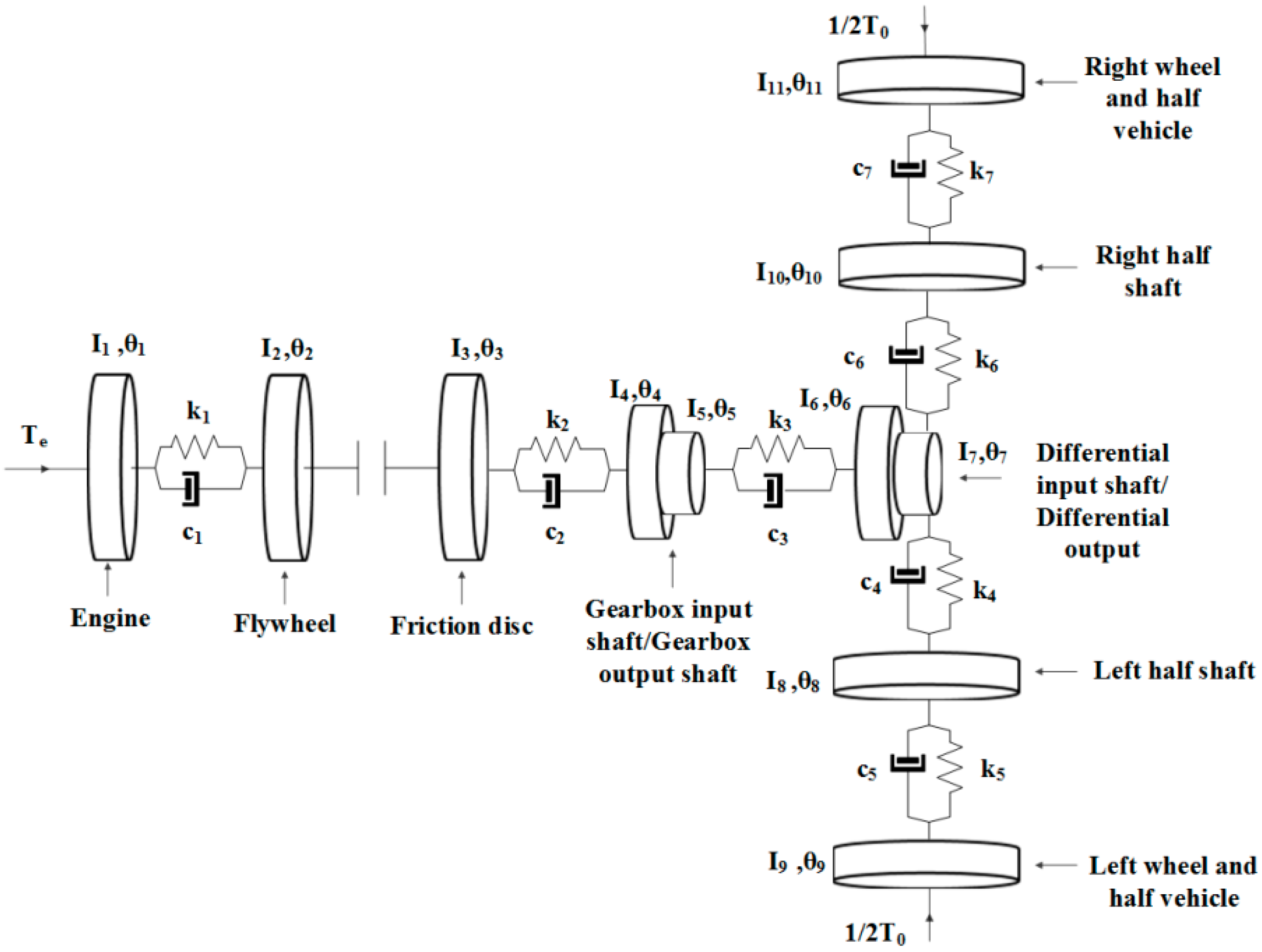
The dynamic representation of the drivetrain system is achieved through a multi-degree of freedom system model. The torsional model comprises 9 degrees of freedom (9-DOF) including a dry friction clutch disc as shown schematically in
Figure 1. Each inertial element represents a component of the powertrain system. The engine is represented by the inertial element,
. The second inertial element,
, represents the flywheel and the third inertial element,
, represents the friction disc. In addition, the fourth and fifth inertial elements,
and
, are those of the gearbox and the sixth and seventh,
and
, are for the differential unit. Inertial elements
and
are designated to the left and right rear axle half-shafts in this rear wheel drive system and
and
inertial elements are those of the left road wheel and half vehicle, the right road wheel and half vehicle respectively.
All inertial components, except those of the gearbox and the differential unit, are connected via shafts with representative torsional stiffness and damping. The angular position of the gearbox and the differential are coupled via constant gear ratios and respectively.
The Equations of motion for the model in
Figure 1 are:
where
is the angular displacement,
is the engine (driving) torque,
is the friction torque and
is the resistive torque. These are described in
Section 2.2 and
Section 2.3. The gearbox and the differential are each represented by an Equation of motion (Equations (10) and (11)). The gearbox input and output shafts are coupled without any change in their initial condition via the gear ratio
as:
Similarly, for the differential, there is the gear ratio
as:
Equations (1)–(9) can be represented in a matrix form under clutch interfacial slip condition as:
where the inertia, damping, and stiffness matrices are given by the relationships (Equations (A1)–(A3)) in
Appendix A.
Under fully locked (i.e., clamped/engaged) clutch state, the degrees of freedom for the system reduces by one, as the second inertial element,
, and the third,
, are now considered as a single lumped inertial element. Thus, the equations of motion (1)–(9) take the following form:
The associated matrices for inertia, damping, and stiffness are given by relationships (Equations (A4) to (A6)) in
Appendix A.
2.1. Damping Coefficients
The proportional damping approach is used for the calculation of the damping coefficients [
22]. Thus, the damping matrix in the general linear form includes the inertias and stiffness matrices, expressed as:
where
and
are scalar multipliers. With the assumption that the system is lightly damped [
23], the scalar multiplier,
is set to zero. Thus:
The stiffness proportionality coefficient,
, is given as:
where
is the damping ratio of the
nth mode and
is its natural radiancy. The natural frequency of the system is obtained by solving the eigenvalue problem:
and the corresponding eigenvectors are obtained from:
The powertrain studied here is that of a light rear wheel drive truck, which is lightly damped. All system specifications are provided by Farshidianfar et al. [
23], showing the damping ratios in the range: 0.01–0.05, which is also in line with those stated for similar systems in [
10]. In the current analysis, a mean value of 0.03 is used for the damping ratio.
2.2. Engine and Resistive Torques
The torsional dynamic model also includes a resistive torque,
, calculated as the sum of rolling resistance,
, and aerodynamic drag,
, thus [
24]:
where
is the laden wheel radius.
Rolling resistance,
depends on the coefficient of rolling resistance,
, mass of the vehicle,
and the angle of the inclination (grading),
:
where
is the gravitational acceleration.
The aerodynamic drag is calculated as [
10]:
where
is the density of air,
velocity of the vehicle,
the aerodynamic drag coefficient, and
is the effective vehicle frontal area.
In the current dynamic model, the engine torque is expressed as the sum of a steady state mean torque,
, and a fluctuating component,
:
The fluctuating part of the torque is represented by a Fourier series in terms of engine order torsional oscillations as [
5,
12,
25]:
where
is the harmonic order of torque,
is the fundamental angular velocity of the fluctuating torque,
, and
is the initial phase. The fundamental angular velocity,
, depends on the engine type. In the current study, the simulated engine is a 4-stroke 4-cylinder engine, where all the cylinders fire in 2 crankshaft revolutions. Therefore, the fundamental angular velocity
[
25], where
is the crankshaft angular velocity.
2.3. Friction Torque
Friction torque appears during the sliding phase in clutch engagement. In order to evaluate the friction torque, the clutch disc is assumed to have an annular shape with
and
as its outer and inner radii respectively. Friction torque is given by integrating the friction torque over the area of the annular surface:
where
is friction,
is radius,
is the effective radius of the clutch [
6,
7],
is the area of the clutch, defined by the inner,
, and outer,
, radii of the friction lining surface respectively. The coefficient of friction is shown by
and
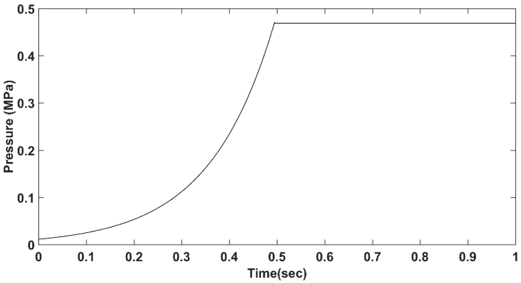
is the applied normal load (generally termed as the clutch clamp load), which in the current study, has a non-linear profile as shown in
Figure 2. Clearly,
needs to be measured and depends on clutch operating conditions, interfacial slip speed, clamp load (contact pressure) and temperature, as well as the clutch lining material type and its wear state.
3. Thermal Analysis
In parallel with the dynamic powertrain model, an analytical dry clutch lumped parameter thermal model is developed, based on the principle of conservation of energy. The lumped parameter model assumes that the temperature within all the elements of the clutch assembly is uniform and thus the interfacial temperatures can be derived. The details of the thermal model are reported in Gkinis et al. [
21]. A brief outline of the thermal model is provided here for the sake of completeness. Temperature is calculated for each of the main clutch system components through a balanced thermal energy flow into and out of the system. Thus, the temporal variance of any component’s temperature is obtained as:
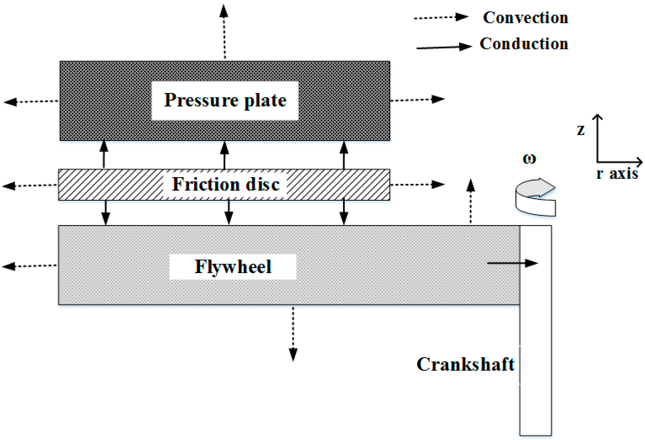
The modelled clutch system components are the flywheel, fw, the friction disc/lining, fd/fl, and the pressure plate, pp, as shown in
Figure 3. The friction disc is considered to have two surfaces and therefore, heat is generated by two sources (contacts), one at each side of the friction disc (i.e., in contact with the flywheel and pressure plate). In
Figure 3, heat transfer is through conduction represented by the solid line arrows and through convection by the dotted arrows. Heat transfer through radiation is ignored as the engagement times are very short with the dominant mechanism of heat transfer being conduction [
26].
As can be seen from
Figure 3, the generated heat on each of the friction disc is conducted into the component in contact with the disc (i.e., the flywheel and the pressure plate). After heat is generated and conducted into these main components, it continues to be conducted through other adjacent bodies such as the crankshaft and transmission system components into air. The amount of heat conducted and convected from each of the components is determined by a heat partitioning method as described in [
21] in detail. In this approach a portion of the generated heat in the contact between the flywheel and the friction lining is assumed to be transferred to the flywheel, whilst the remainder is transferred to the friction lining material. Similarly, the heat generated between the pressure plate and the friction lining is also partitioned between the two surfaces. The exact values for the portions of generated heat transferred to each component are obtained through considering the thermal resistances in each heat flow direction and the ambient conditions.
The frictional power loss produced in the system defines the generated heat in the contact between the mating surfaces. Assuming that all frictional losses in the contact convert to thermal energy and the normal load are applied uniformly, the frictional power loss generated between the mating surfaces can be calculated as [
21]:
where
is the number of frictional interfaces (2 in the current analysis),
and
are the inner and outer radii of the clutch disc,
is the normal contact load,
is the interfacial coefficient of friction of the contacting surfaces, and
is the relative angular velocity between the friction disc and the flywheel/pressure plate. The coefficient of friction in this analysis is considered to vary with the sliding velocity, the applied contact pressure, and the operating temperature.
Applying Equation (32) for each of the main components of the clutch system (friction disc, flywheel and the pressure plate) and taking into account the heat fluxes as portrayed in
Figure 3, three differential equations are obtained for the friction disc, flywheel and the pressure plate as:
where
is the heat conducted to the friction disc from the flywheel side,
is the heat conducted to the friction disc from the pressure plate,
is the heat conducted to the flywheel and
is the heat transferred through conduction to the pressure plate. The heat convected from the inner and outer radii of the friction disc is denoted as
and
. For the flywheel,
represents the portion of the heat generated in the flywheel/friction disc interface and conducted to the flywheel,
represents the heat that is conducted from the friction disc. In addition,
and
represent the heat convected from the outer radius, the inner uncovered area and the heat dissipated from engine side of the flywheel. Finally, for the pressure plate
represents the proportion of the heat generated from the friction disc/pressure plate interface and conducted to the pressure plate and
is the heat conducted from the friction disc. The convected heat from the inner and outer radii and transmission side of the pressure plate is represented by
,
, and
.
4. Measurement of Coefficient of Friction and Thermal Transport Properties
The coefficient of friction used in the current analysis is obtained through pin-on-disc tribometry. The frictional characterization of the clutch lining material is performed under realistic vehicle clutch engagement conditions. It was, therefore, ascertained that the pressures developed in the contact between the pin and the disc are similar to those in a real vehicle clutch contact. In addition, the rotational speed of the disc was adjusted so that the relative sliding speed between the pin and the disc was representative of that occurring between the actual clutch components in a real vehicle during take-off. Furthermore, the disc was equipped with a heating element that allowed for heating of the contact between the pin and disc to the bulk temperatures that exist in a real clutch contact in a vehicle [
13]. The friction lining materials used for the tests were cut from a real vehicle clutch lining material.
Table A1 in
Appendix A provides information about the load and speed conditions in the real vehicle clutch contact and those simulated by the pin-on-disc tests. Each measurement included new samples and the tests for each sample were repeated six times [
12,
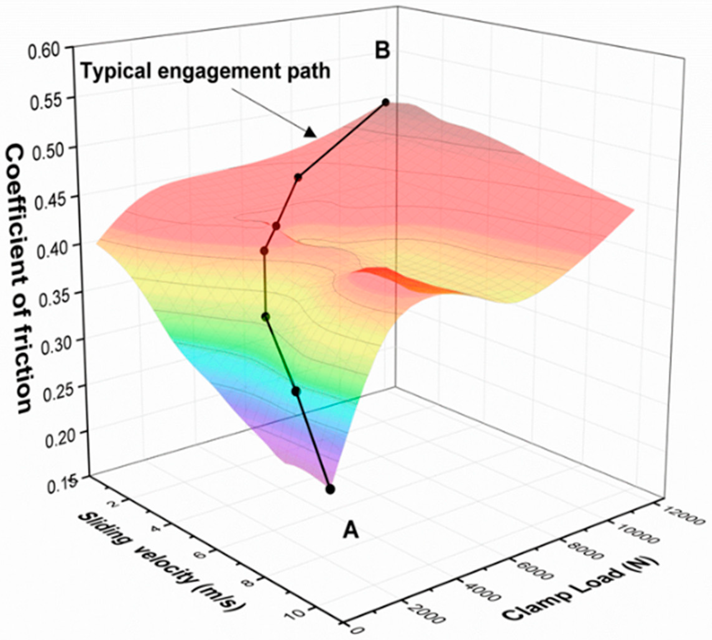
13]. Following the completion of friction measurements, a carpet plot is produced, for frictional characteristics of the clutch lining (a sample of which was attached to the pin of the pin-on-disc tribometer) in contact with the surfaces of either the pressure plate or the flywheel, used as the disc under various operational conditions such as slip speed and clamp load (
Figure 4).
Figure 4 also shows a typical engagement path, depicted by the black line. The letters A and B represent the beginning and the end of the engagement process. This is a typical friction lining characteristic which varies according to the lining composition as well as its wear state (i.e., age). It is noteworthy that variation of coefficient of friction with slip speed mostly exhibits a negative slope. Therefore, depending on the negativity of this slope (according to lining type and wear state) and other operating conditions such as loss of clamp load and operating temperature, the propensity to judder alters.
Here, two actual clutch samples are investigated. These include a new (unused) sample and a worn one, both of the same lining type. The purpose is to investigate the clutch lining performance at different stages of its life. The worn clutch sample is acquired from a passenger vehicle clutch after 100,000 km. This sample has undergone running-in wear and embedding processes, nearing its end of life. A detailed description of the acquired coefficient of friction (COF) through use of tribometry and the methodology followed are presented by Gkinis et al. [
12,
21].
Table 1 provides the results of tribometric measurements for the coefficient of friction variation with clutch interfacial slip speed at different surface temperatures of the disc, representing the surface of the pressure plate and made of the same steel with representative surface topography. The extrapolated linear regressed equations in each case are for all the results, representing lines of constant pressure (at full clamp load) in the overall frictional characteristic carpet map, similar to the one shown in
Figure 4. The intercept of these lines corresponds to the static coefficient of friction. These show 30% higher static COF for the new lining material than that for its worn/used counterparts. All the results show a negative gradient for the COF variation with slip speed. However, the negative slope alters more rapidly with temperature for the case of the new lining. The combination of higher static coefficient of friction and a larger negative slope with slip speed indicates that more severe stick-slip vibrations would occur during engagement with the new lining material when torsional variations in engine torque induce interfacial oscillations. Furthermore, the depletion of effective thermally conductive constituents in the lining material with prolonged usage and wear is also reported in [
21]. With the bedded (worn) lining, the variation between stick and slip coefficients of friction is reduced due to decreased static coefficient of friction as well as a more gradual slope with slip speed. Therefore, less severe intermittent stick-slip would be expected. Simulations with the multi-degrees of freedom model reported in
Section 5 corroborate these observations. It should also be noted that judder is an error state, but not a failure state. Worn clutches malfunction due to the loss of bite point and clamping ability.
Similarly, as for the COF and thermal conductivity of the lining, the specific heat and thermal diffusivity of the various lining states were also measured. These measurements of thermal transport properties were performed, using the Hot Disk TPS 2500 S (Hot Disc AB) thermal constant analyzer which operates on the basis of the transient plane source method. This method utilizes a thermal conductive plane sensor that also acts as a heat source. The sensor/source is placed between two samples of the material under investigation. As the temperature of the source/sensor increases, the generated heat dissipates through the material. Subsequently, the heat dissipation rate is measured, and the thermal transport properties of the material are calculated.
5. Combined Thermal-Dynamic Analysis
The Equations of motion (1)–(9) for the case of slipping at the clutch interface during clutch engagement and Equations (13)–(20) for the fully clamped clutch state are solved numerically as a system of dynamic equations of motion, together with the thermal differential equations of the clutch, based on Equation (32). The dynamics and thermal equations are coupled together into a single thermal-dynamics model by transient angular velocities, which are an output of the dynamics model and serves as an input to the thermal analysis. The 4th-order Runga-Kutta step-by-step integration algorithm is used for the solution of equations of motion. The initial engine speed at the instant of clutch actuation is chosen as 100 rad/s or an equivalent engine speed of 960 r/min, which is the idle engine speed for the vehicle under investigation. The duration of clutch engagement is set at 0.5 s, as can be seen in
Figure 2 in line with the range reported by Centea et al. [
6,
7]. Additionally, the initial temperature for all clutch elements under consideration was set to 20 °C (the average ambient Spring/Summer temperature in the UK). Additionally, the temperature of the engine and the surrounding compartments is considered to be constant at 20 °C (start-up conditions) for the short duration of the simulation. All the parameters used in the model are listed in
Table A2,
Table A3 and
Table A4 in
Appendix A.
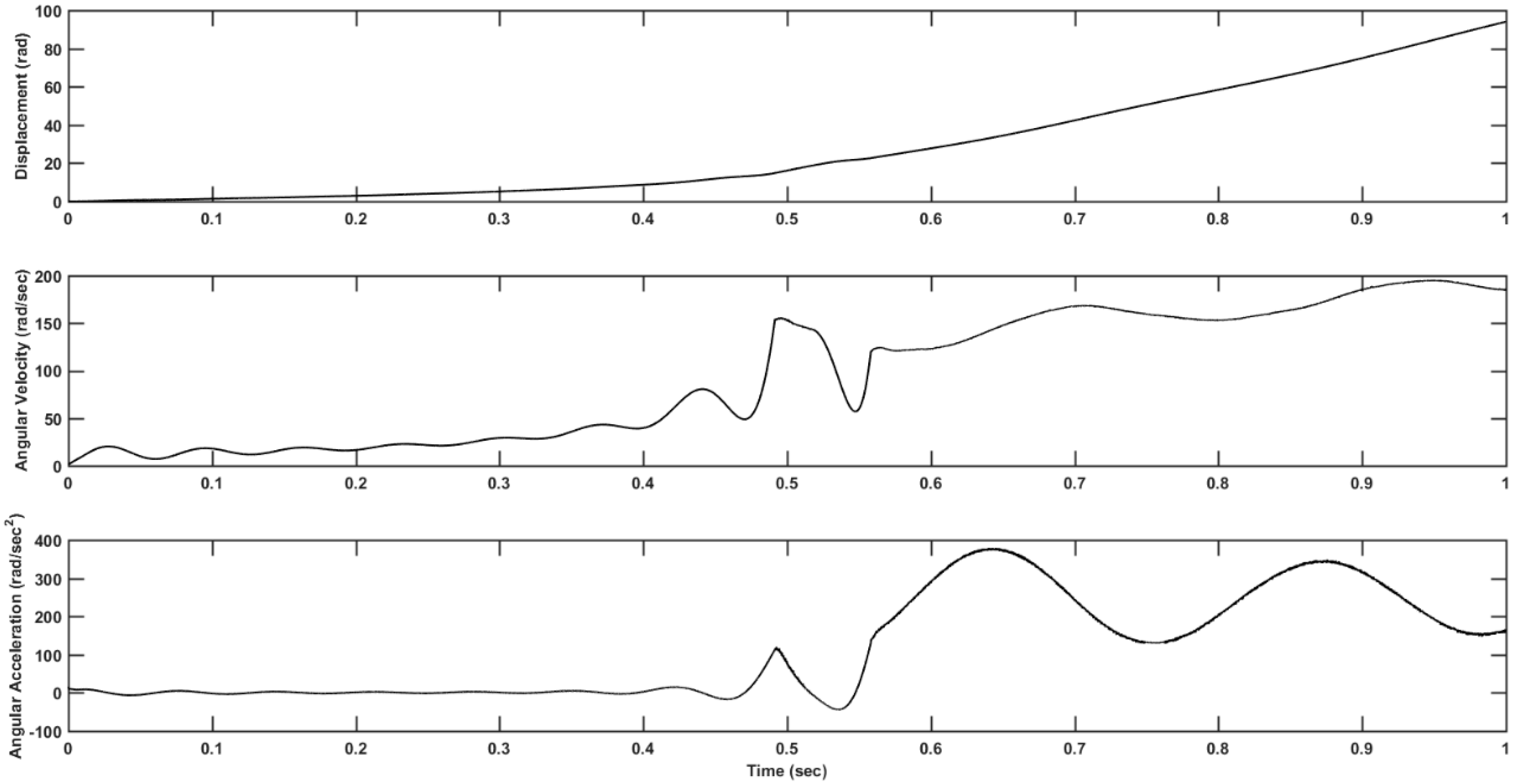
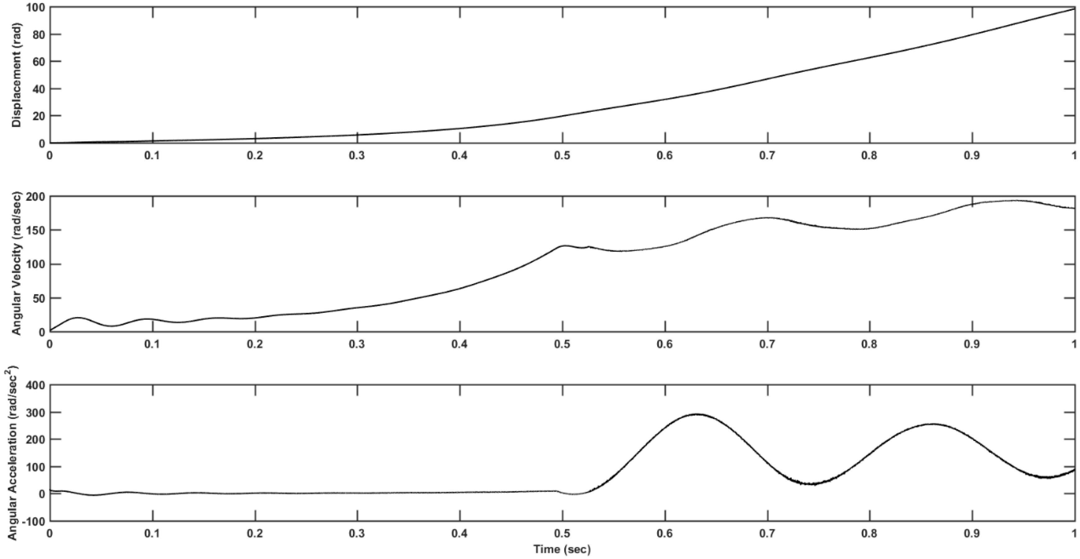
Figure 5 and
Figure 6 show the variations in displacement, angular velocity and angular acceleration of the clutch friction disc during a single clutch engagement for the new and worn clutch friction linings. The main differences in the characteristic responses for the new and worn lining materials are in the variations of angular velocity during clutch engagement. Close to full engagement, stick-slip oscillations occur in the form of sudden angular velocity fluctuations (
Figure 5). Additionally, the stick-slip oscillations can also be noted in the abrupt angular acceleration reversals. Larger negative
μ-
v characteristic in
Table 1 for the new lining material provides good explanations for the observed judder vibrations in
Figure 5 for the new lining material. This is in line with the other findings such as Centea et al. [
6,
7] and Gkinis et al. [
12].
Figure 7a shows the temperature rise for the new friction lining for a single clutch engagement, whilst
Figure 7b is the same for the case of the worn lining. Higher interfacial surface temperatures are reached in the case of the new lining, owing to higher generated friction. It should be noted that as the thermal analysis uses a lumped-parameter model, any rise in the temperature should be considered as a bulk temperature rise. The flash temperature rise in the contact is expected to be higher than the rise in the bulk temperature. Nevertheless, any rise in the bulk temperature can be considered as an indication of a rise in the contacting surface temperature where frictional heating takes place. The new friction material reaches a temperature of 22.4 °C for a single engagement, whilst the temperature of the worn lining reaches 21.3 °C (Noting that in both cases an initial temperature of 20 °C is assumed). The temperature of counter face surfaces of the flywheel and pressure plate is almost the same in both cases. The difference in temperature between the new and worn friction linings (with respect to the rest of the clutch elements), can be attributed to the different thermal transport properties associated with the ageing of the worn lining.
The higher temperature for the new lining material is due to higher contact friction as well as increased take-up judder oscillations during clutch engagement. Stick-slip oscillations and the associated excess acceleration contribute to the quantity of generated contact heat. It is noteworthy that severe angular velocity variations occur around 0.5 s into the clutch engagement process induce a step-type rise in the temperature. However, as time elapses the slope of rise in angular velocity reduces and vibrations are attenuated. Therefore, the rise in temperatures slows down as shown in
Figure 7a. This is in agreement with
Figure 7b, where the temperature rise follows a smoother path. This behavior can be attributed to the reduced/lack of stick-slip oscillations in the case of worn lining material as can be seen in
Figure 6. Another noteworthy observation is the dominant effect of COF in comparison with the thermal transport properties of the lining material, particularly its thermal conductivity. The new friction material has a thermal conductivity almost double that of the used friction material but reach higher operating contact temperatures.
The effect of consecutive and prolonged clutch engagements is shown in
Figure 8.
Figure 8a,b present the temperature variation in the main clutch components with time for the new and used friction lining material respectively, for the first maneuver.
Figure 8a shows that the bulk temperature of the friction lining material reaches a value just below 60 °C for a series of consecutive engagements at a constant realistic engagement time of 0.5 s. The pressure plate surface reaches a temperature of around 55 °C and the flywheel reaches a temperature of around 45 °C for the same conditions. The temperature variation between the pressure plate and the flywheel surfaces is because of the exposed free surface geometry of the flywheel facing the engine, leading to a greater convective heat transfer thus a lower temperature. The temperature of the used friction material after the same series of consecutive engagements reaches a temperature of approximately 50 °C, a difference of 10 °C compared to the new lining. The final temperature reached after the consecutive engagements can also be attributed to the different COF of the clutch materials.
6. Conclusions
The paper presents a 9-DOF torsional dynamic model of a rear wheel drive light truck powertrain system developed for the investigation of the effect of clutch lining frictional characteristics on clutch system dynamics and thermal performance.
The results of the experimentally measured COF indicate that the worn friction lining material exhibits different frictional behavior than the new lining. The coefficient of friction of the used material is found to be lower than that of the new specimen by up to 20%. Additionally, the gradient of the μ-v characteristic curve of the worn material is almost flat as the COF is not susceptible to sliding velocity. Subsequently, different vibrational behavior is observed in simulating worn and new lining materials. There are clear and severe oscillations during clutch engagement in the case of the new friction material, termed as take-up judder.
The results derived from the above combined models indicate that take-up judder vibrations for a single clutch engagement can increase the temperature of the clutch system components when compared with the case of smooth (ideal non-oscillatory) engagement. The results indicate that the coefficient of friction of the clutch lining material and its thermal transport properties have a critical effect upon rising clutch system temperatures. The outcome of this study demonstrates the strong connection between vibration phenomena such as take-up-judder and clutch system thermal performance. The developed model can potentially be expanded and/or utilized to examine the effect of thermo-mechanical properties of clutch lining materials and their behavior at different stages of their lifespan. This would allow for prediction of their optimal operational range including for engagement timing, whilst the subsequent issues on clutch system vibration and vehicle Noise, Vibration and Harshness (NVH) can also be considered simultaneously.
