Article

INS/Vision Integrated Navigation System Based on a Navigation Cell Model of the Hippocampus

Key Laboratory of Instrumentation Science & Dynamic Measurement, Ministry of Education, School of Instruments and Electronics, North University of China, Taiyuan 030051, China
*
Authors to whom correspondence should be addressed.
Appl. Sci. 2019, 9(2), 234; https://doi.org/10.3390/app9020234
Submission received: 26 November 2018 / Revised: 28 December 2018 / Accepted: 5 January 2019 / Published: 10 January 2019

Abstract

:
Considering the error accumulation problem of a pure inertial navigation system (INS) under the condition of satellite signal outages, this paper proposes a brain-like navigation method based on a navigation cell model of the hippocampus to improve the accuracy and intelligence of the INS. The proposed method employs vision to acquire external perception information as an absolute reference for INS position error correction, which is established by analyzing the navigation mechanism of the rat brain. The prominent advantages of the presented method include: (1) a remarkable effect in reducing the accumulated errors of INS can be obtained; and (2) a hardware implementation procedure of an INS/vision brain-like navigation system on a single-chip microcomputer is designed and established, which makes possible the engineering application of the brain-like navigation system by providing technical detail. Also, an outdoor vehicle test is carried out to verify the superiority of the proposed INS/vision brain-like navigation system in position measurement. Finally, the optimal performance shows the effectiveness of the proposed method in accumulated error correction and accuracy improvement for INS.

1. Introduction

Nowadays, navigation technology has an increasingly profound impact and changes our lives in various aspects, from deep sea voyage to soaring in the sky. Even in an unfamiliar environment, we can easily get the current location and reach the destination with the help of navigation maps, which are mainly based on global positioning system (GPS) [1]. Nevertheless, we may be confronted with satellite signal outages in some locations, such as urban canyons, tunnels, deep mountains and forests, and so on. [2]. An inertial navigation system (INS) demonstrates its unique superiority in various application scopes, which is embodied in a high degree of autonomy, being independent of external information, using no radiation energy, and being applicable in all weather conditions [3]. However, due to integral calculation, navigation errors gradually accumulate with time, and then the long-term accuracy of an INS is difficult to guarantee. In addition, inertial sensors are unable to perceive external information, which means that the INS cannot eliminate the accumulated errors through its own perception.
To reduce accumulated navigation errors and improve the intelligence of an INS, researchers have found that navigation strategies combining one or more navigation technologies with the INS can obtain complementary advantages and achieve better navigation results, where GPS/INS is a typical integrated navigation system, especially for land vehicles. The system is heavily dependent on GPS, a passive navigation system, which is easily blocked or invalidated by human or external environmental factors [4]. As a result, the overall performance of the integrated navigation system may be affected. Due to using no radiation energy, working in all weather conditions, covering all areas and having low energy consumption, INS/geomagnetic integrated navigation systems have received wide attention and research [5]. However, the accumulated velocity and position errors cannot be eliminated fundamentally. Besides, if the local magnetic information is abnormal, the geomagnetic system itself introduces navigation errors. Additionally, the combination of an odometer, Doppler instrument, Wi-Fi, Ultra-Wideband (UWB) and INS has also been widely studied [6]. It is worth noting that by fusing the information from auxiliary sensors and the INS, the current integrated navigation systems do not have intelligent abilities.
To endow a navigation system with intelligent abilities, the attention of researchers is turned to the biological world, and they learn from animals to study their intelligent navigation mechanisms. Carrier pigeons have an autonomous homing ability. Rats can always find their way home. Insects such as bees and sand ants can return to their nests hundreds of meters away along a straight line after complex and tortuous foraging processes in the absence of significant references [7]. Research results show that by perceiving surrounding environments, animals can obtain accurate navigation information. In 2014, the Nobel Prize in Physiology or Medicine was awarded to scientists who discovered the animal’s brain navigation system [8]. They revealed that a type of neuron is responsible for location remembering, and is located in an encephalic region called the hippocampus of the rat brain. The main functional cells include speed cells and place cells. The above research results show that when animals move, they realize autonomous navigation by perceiving information in the external environment and combining it with internal cells [9]. Actually, when animals reach a familiar place, the path integrator of the brain will be reset to adapt to the environment information sensed by eyes, which means that the integrated position error can be corrected by the recognition of familiar places, which can be recognized as absolute position references. By capturing external artificial or natural information, vision navigation systems can realize the calculation of navigation parameters and achieve high precision during long journeys [10,11,12,13]. In 2004, a bionic place recognition algorithm, named RatSLAM, was proposed. Then, SeqSLAM, which is the improvement of RatSLAM, was proposed in 2012 with higher recognition accuracy and wider range. However, the above vision navigation methods are not used for information fusion with INS data, and therefore cannot improve the intelligence degree of an INS.
Inspired by the above research, this paper proposes a brain-like navigation scheme based on an INS/vision integrated navigation system. The system is intended to impart the environmental perception ability of the vision navigation system, and the intelligent navigation ability of the hippocampus navigation cell model, to the INS, and eventually endow the brain-like navigation system with strong autonomy, high intelligence and high reliability. The contributions of this paper are as follows:
(1)
The INS/vision brain-like navigation model is proposed. In our model, the camera is employed for environmental perception as the eyes of animals, and the INS is used for velocity and position measurement as the path integrator based on the speed cell model. The place cell nodes are established by storing feature scene pictures in the system and associating them with corresponding accurate position information. When the carrier moves, the images captured by the camera are matched with the stored feature scene pictures. When the match is successful, the place cell node is triggered, and its corresponding accurate place information is fed back to the INS to correct the accumulated position error. At the same time, the INS adjusts the path integration mechanism to reduce the error of the path integrator.
(2)
The INS/vision brain-like navigation system is built on an STM32 single-chip computer and LattePanda (a kind of card-type computer). The complete circuit board includes the main controller, namely STM32, and two main functional components, which are the INS and the camera based on LattePanda. The main board is composed of an ADC analog-to-digital conversion chip, Bluetooth module, various voltage regulating circuits, and so on. STM32 and LattePanda communicate through the serial port. The hardware system can realize real-time information processing of the proposed brain-like navigation system.
The paper is organized as follows: Section 2 briefly describes the concept of speed cells and place cells, and proposes the INS/vision brain-like navigation model. Section 3 introduces the hardware design. Experiment and comparison results are shown in Section 4. The paper ends with a conclusion in Section 5.

2. Brain-like Navigation Model

2.1. Speed Cells

It had been found long ago that birds can control the time to arrive at their destination when migrating, and desert ants can grasp the speed of navigation well when they are foraging, which demonstrates that they can obtain speed information through perception [14,15,16]. Fyhn and Hafting studied the phenomenon of free movement of rats in their space environment, and found that neurons with specific discharge activity occurred in different environments. Repetitive discharges occur in a specific region of the spatial environment, and numerous discharge fields of the neuron cell overlap into one node. During the movement, the discharge rate of the particular cell is in proportion with the motion speed. Specifically, it is independent of the direction of movement and the surrounding environment, but only related to the speed of motion. Thus, they are called speed cells, and Figure 1 shows the schematic diagram of speed cell discharge.

2.2. Place Cells

The position of a vehicle can be obtained by a speed integral. Naturally, the speed error will cause position deviation accumulation, which is not the desired phenomenon during navigation. Also, the position error cannot be compensated for without external environment constraints. Actually, it has been found that sea turtles use landmarks to form maps, providing place constraints during their long-distance travel. Saharan Desert ants are able to cross the desert and return to just where they started, because a large amount of landmark information forms a map, by which they can construct place constraints [17,18]. O’Keefe found place cells in the upper reaches of the mammalian hippocampal region, and also found that the activation of place cells corresponds to certain areas in the environment. All location cells are linked together in a certain way, forming a spatial cognitive map, as shown in Figure 2.
As shown in Figure 2, when the rat moves into a certain place, the cell group A is activated, and the other cells are dormant. When the rat moves into another place, the cell group B is activated and other cells are dormant. The yellow dots represent a set of activated cells, with only one region of the site cells activated, and the gray lines represent the rat’s trajectory.

2.3. INS/Vision Brain-like Navigation Model

Biological research shows that single navigation cells cannot help animals to travel long distances. The process of sensing velocity by speed cells and integrating it to obtain position information will produce serious accumulation errors, which will make the travel farther and farther away from the destination during long-distance journeys [19]. The place cells can be used for location by identifying landmarks. However, the landmarks are not continuous and there is no fixed distance between them. Just relying on landmarks will lead to many detours. To accurately reach the destination, animals travelling far away combine multiple navigation cells together. The position information is obtained by the integral of velocity perception information from the speed cell. Also, the position error induced by the integral calculation can be corrected by a place cell by means of perception of the external landmark information.
For a pure INS, the attitude, velocity and position information can be obtained by an integral using the measured angular velocity and acceleration. As navigation information is obtained by integration, the error increases with time, resulting in the gradual decrease of navigation accuracy. To reduce the error accumulation, and inspired by animal navigation cell models, we propose the brain-like navigation model based on an INS and vision navigation. Among them, the INS module is similar to the speed cell, used to obtain the position information by the integral of the measured velocity. The vision navigation system is similar to the place cell, using scene matching to identify the landmark and to further correct the position accumulation error of the INS. The hardware system of visual navigation based on a LattePanda development board and the INS based on an STM32 are also built, as shown in Figure 3. The specific procedure is to transplant the image matching algorithm into the LattePanda development board. The vision navigation system matches the real-time acquisition images with the pre-stored images. When the match is successful, the place information of the pre-stored image, as the current place information, is fed back to the INS through serial communication to correct the INS system. Then, the INS computation process renews at the current place. At the same time, the INS path integrator is compared with the visual matching place node to consider the sources of error. Based on this, the path integral is adjusted to reduce the errors, as shown in Figure 4. By using this method, the accumulated errors of the INS can be effectively eliminated, and the accuracy of navigation can be improved.
With the camera installed onto a vehicle, if the relative height and inclination of the camera are the same as the ground, for two different images taken at the same location, it can be regarded as a horizontal deviation, but there is no vertical deviation. Therefore, the region of interest of the template image can be moved from the reference image, which is the similarity of the corresponding relationship. In this way, the region of the two images after each shift can be calculated, and the minimum of all similarity values can be taken as the final similarity of the two images.
To determine place cell nodes, distinctive landmarks are considered, such as symbolic buildings, crossroads, and so on. As sufficient feature points can be used in such scenarios, they are often selected as place cell nodes. Another reason is that images in such scenarios can be obtained not only by precapturing but also from an online picture database. Then, the oriented FAST and rotated BRIEF (ORB) algorithm extracts feature points from video images and tries to match the video image with the template image. The feature points have the information of size and orientation. By matching feature points between the video image and the template image, the distance of the matched points can be determined. The minimum distance of matched points is set as the Hamming distance. For other matched points, if their distance is less than two times of Hamming distance, it is concluded that the two points match successfully. Otherwise, the matching between these two points cannot be used. When the distances of all matched points are examined, the next image is read.
As shown in Figure 4, after successfully matching the scene with the vision navigation system [20,21,22], the accurate place information X 2 of the pre-stored scene is sent to the INS. The INS system is also integrated to obtain place information X 1 . At the same time, the total time t from the last place node to the currently successfully matched location is recorded. By subtracting the calculated place information X 1 from the accurate place information X 2 , we can obtain the accumulated error X e r r during time interval of t . The accumulated error is obtained by:
X e r r = X 2 X 1 ,
X 2 = V 1 · Δ t + V 2 · Δ t + V 3 · Δ t + V 4 · Δ t + + V n · Δ t .
The velocity signal is a continuous variation. Since the s collected by the single-chip microcomputer is a discrete signal, the calculated velocity information is also a discrete signal. V 1 , V 2 , V 3 , V 4 , …, V n is the velocity of every Δ t in t time, and X is the travel distance in time t .
{ V 2 = V 1 + a 1 · Δ t V 3 = V 2 + a 2 · Δ t = V 1 + a 1 · Δ t + a 2 · Δ t V 4 = V 3 + a 3 · Δ t = V 1 + a 1 · Δ t + a 2 · Δ t + a 3 · Δ t V n = V n 1 + a n 1 · Δ t = V 1 + a 1 · Δ t + a 2 · Δ t + a 3 · Δ t + + a n 1 · Δ t
Since there is no regular change of acceleration in the course of motion, the acceleration cannot give a definite relation. a 1 , a 2 , a 3 , …, a n 1 stands for the actual acceleration per Δ t in time. We substitute Equation (3) into Equation (2):
X 2 = V 1 · Δ t + ( V 1 + a 1 · Δ t ) · Δ t + ( V 1 + a 1 · Δ t + a 2 · Δ t ) · Δ t + + ( V 1 + a 1 · Δ t + a 2 · Δ t + a 3 · Δ t + + a n 1 · Δ t ) · Δ t
The cumulative error of the INS location is mainly caused by the error of accelerometer. a 1 , a 2 , a 3 , …, a n 1 is converted to the geographic coordinates of acceleration, and the error of the accelerometer is assumed to be equal to a e r r in a short period of time. Thus the location X 1 obtained by the INS is as follows:
X 2 = V 1 · Δ t + ( V 1 + a 1 · Δ t ) · Δ t + ( V 1 + a 1 · Δ t + a 2 · Δ t ) · Δ t + + ( V 1 + a 1 · Δ t + a 2 · Δ t + a 3 · Δ t + + a n 1 · Δ t ) · Δ t
a e r r = a a .
Substituting Equations (5) and (6) into Equation (1):
X e r r = a e r r · ( Δ t ) 2 + 2 · a e r r · ( Δ t ) 2 + + ( n 1 ) · a e r r · ( Δ t ) 2 .
Hence:
a e r r = X e r r / ( ( n · ( n 1 ) 2 ) · ( Δ t ) 2 ) .
In the STM32 single-chip microcomputer, the calculation frequency of the INS is set to 40 Hz. Thus,
n = t · f I N S .
Substituting Equation (9) in Equation (8):
a e r r = X e r r / ( t · ( t · f I N S 1 ) 2 · f I N S ) .
Due to the accumulation of errors, the velocity of t moment has deviated from the true velocity. In order to reduce the error in the later calculation, the velocity V t of t time should be calculated again by using the saved acceleration information.
V t = V 1 + a 1 · Δ t + a 2 · Δ t + a 3 · Δ t + + a n 1 · Δ t
Put Equation (6) in Equation (11):
V t = V 1 + ( a 1 + a e r r ) · Δ t + ( a 2 + a e r r ) · Δ t + ( a 3 + a e r r ) · Δ t + + ( a n 1 + a e r r ) · Δ t
The V t is closer to the true value, so it can be used as the starting velocity of the next stage, which provides a guarantee for improving the subsequent velocity calculation and place integral accuracy.

3. Results Construction of INS/Vision Brain-like Navigation Hardware System

The block diagram of the INS/vision brain-like integrated navigation system is shown in Figure 5, which is mainly composed of the inertial navigation system and the vision navigation system.

3.1. Construction of the INS Hardware System

The inertial sensors used in the hardware system comprise an accelerometer (1521L-010, measurement range: ± 10 g) and a gyroscope (STIM202, measurement range: ± 400 °/s).

3.1.1. Analog Signal Collection

The 1521L-010 accelerometer is powered by ± 5 V with low noise and high stability, and the sensitivity is 200 mV/g. It is noted that the output signal is an analog value which can be converted into a digital signal by an analog-to-digital converter (ADC) chip. The ADS131a04 is an ADC that has low power, four channels, simultaneous sampling, is 24-bit, has delta-sigma modulation and the output rate is 128 K samples per second (SPS). In addition, synchronous acquisition of data depends on the output protocol of the serial peripheral interface (SPI). Compared with other transmission modes, such as the inter-integrated circuit (IIC) or the universal asynchronous receiver/transmitter (UART), the SPI transmission rate is faster, which makes it more suitable for real-time calculation of navigation parameters.

3.1.2. Serial Data Collection

In the process of serial data collection, the RS422 interface is used as the transmission mode of STIM202. As we all know, RS422 has high anti-interference ability and avoids the interference of noise in the transmission process, and the transmission rate can up to 460,800 bits/s. The serial port interrupt mode is applied to receive data. It is noted that the interrupt priority level is set to the second level. In addition, in order to avoid mutual interference between the data, the frame head and frame tail of the data are set to trigger the receiving mode of serial data communication. Furthermore, we can determine whether the received data has an error code or not by judging the number of significant bits of the received data.

3.2. The Construction of the Vision Navigation Hardware System

The vision navigation system is based on the Swiss core LattePanda expanding board with a main frequency of 1.8 GHz. It has a rich I/O interface. LattePanda records video by the time through the camera, and matches the video with the picture node based on an image matching algorithm [23], then the precise position coordinates are sent to the STM32 single chip through the serial port after successful matching.

3.3. The Construction of the Brain-like Combined Hardware System

The design of the core board mainly takes STM32 as the control unit. The circuit board integrates the INS system, vision navigation system and other sensors, and the core board mainly comprises a Bluetooth module, LED circuit, various stabilized modules, RS244-to-TTL circuit, SPI interface, and so on. The microprocessor processes the data from sensors, and calculates the position, velocity and attitude of the motion carrier.
This program depends on the timer of the STM32, and the interrupt mode can be triggered every 25 ms. The timer count frequency f 1 is:
f 1 = f fdr = 84 M 8400 = 10 kHz .
In this case, the working frequency of the STM32F103VGT6 is as high as 84 MHz, and the timer count frequency is 10 kHz.
The interrupt time is:
t br = num f 1 = 250 10 k 1000 = 25 ms .
For a total number of 250 counts, the interrupt time t b r is 25 ms.

4. Experiment and Verification

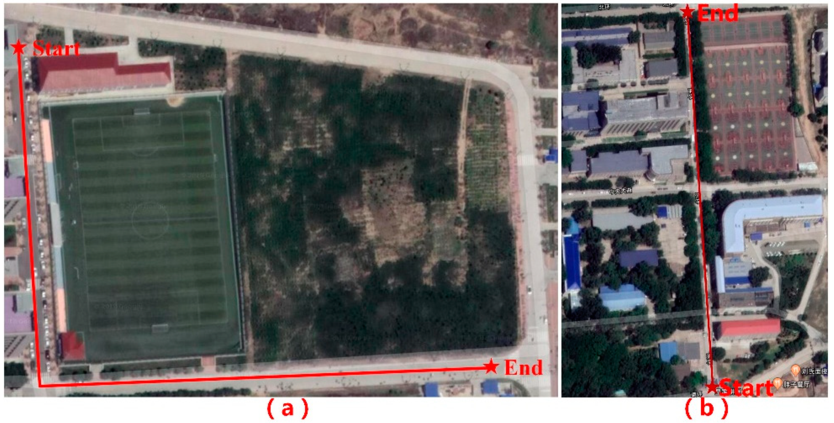
In order to verify the performance of the INS/vision brain-like integrated navigation system based on an STM32 and LattePanda, the on-board test is carried out using a high-precision fiber-optic INS/differential GPS system as a reference, and the experimental trajectory is recorded from the Science Building to Longshan Restaurant, and Fifth Gate to the Science Building, of the North University of China, Taiyuan, Shanxi Province, China. The setup of the experimental platform is shown in Figure 6. It is noted that the geographical location of the experiment is 38.02° N latitude ( L 0 ) and 112.44° E longitude ( λ 0 ).
The starting point of the first experiment is 38.01776° N latitude and 112.44491° E longitude. The vehicle test is terminated at the intersection after heading south and then heading east at the first crossroads, which can be seen vividly in Figure 7a. The starting point of the second experiment is from Fifth Gate at 38.01331° N latitude and 112.44529° E longitude to the Science Building, which can be seen vividly in Figure 7b.
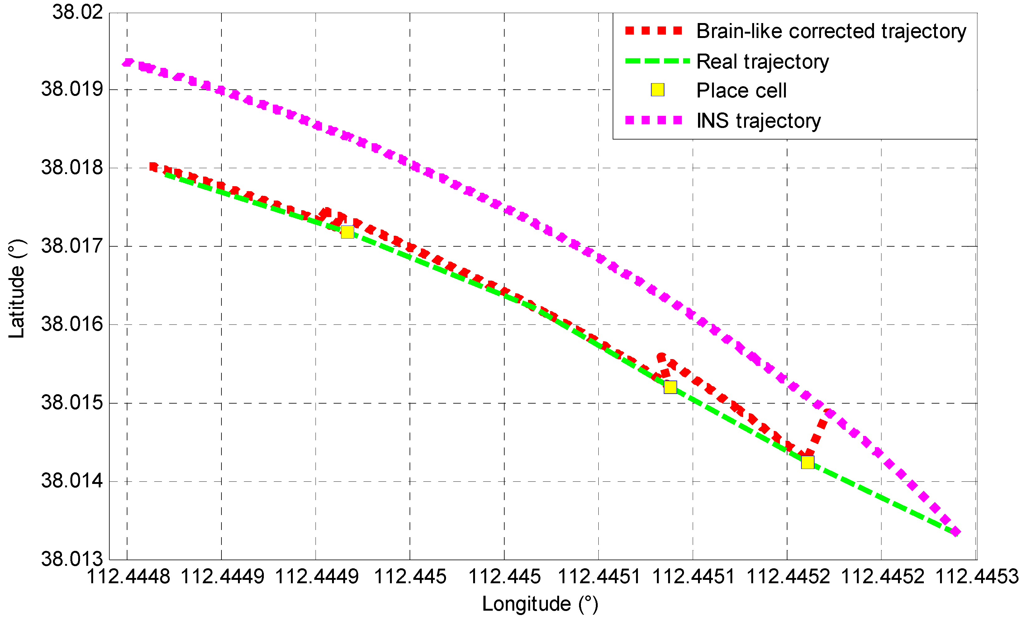
In addition, four place cell nodes are set up in the whole path, and all of them are successfully matched. When the place cell node is activated, the accurate place information stored by the place cell node is fed back to the INS, so as to correct the accumulated position error of the INS, which can be seen in Figure 8. In total, the experiment is carried out over 462 m and lasts 4 min. The experimental results are shown in Figure 8 and Table 1.
To further verify the proposed method, another experiment is conducted. The experimental trajectory is also in the campus of North University of China but with a different trajectory, which is from Fifth Gate to the Science Building. In this experiment, three place cell nodes are set up, and the experiment traveled about 500 m, which is shown in Figure 9. It can be directly seen that this time, the vehicle traveled in a straight trajectory, which is different from the previous trajectory. The place experiment results of latitude and longitude are given in Figure 10.
Figure 9a and Figure 11 represent the motion trajectory of the vehicle. In order to highlight the efficiency of the proposed brain-like navigation method, several different solutions are also investigated for comparison, which comprise the pure INS mode method and the traditional image matching correction method. From the Figure 9a, we can see that the position error based on the pure INS system is accumulated obviously as time goes on, and the position measurement accuracy is improved obviously compared to the pure INS mode after adding the image matching correction method. In addition, it is noted that the red line in Figure 9b,c represents brain-like corrected trajectory errors, and the position error estimated by the brain-like navigation method is fed back to the INS to correct position accuracy according to the proposed method. It is obvious that the positioning result is improved and closer to the true value of high-accuracy trajectory.
Figure 9b,c represent the latitude and longitude errors, respectively. The blue line in Figure 9b is the pure INS position error, the green line is the position error based on the traditional image matching correction method, and the red line represents the error obtained by the brain-like navigation method. As we can see from the Figure 9b,c, the position error estimated by the brain-like navigation method is improved compared with the traditional visual correction method and the pure INS mode. From Table 1, we can see that the mean error of latitude calculated by the traditional image matching correction method is reduced by 61.6% compared with the pure INS mode, and the mean error estimated by the brain-like navigation method is reduced by 15.5% compared with the traditional image matching correction method. In terms of longitude error estimation, the error obtained by the traditional image matching method is reduced by 2.7% compared with the pure INS method, and the error obtained by the brain-like navigation method is reduced by 1.6% compared with that of the traditional image matching correction method.
At the same time, the root-mean-square error (RMSE) and standard deviation (SD) of the position estimated by the brain-like navigation method are smaller than the traditional image matching correction method and pure INS mode. In a word, the above experimental results prove the validity and correctness of the proposed brain-like navigation method.

5. Conclusions

Based on the principle of animal brain navigation cells, a novel INS/vision brain-like navigation method is proposed to improve the position measurement accuracy of an INS by establishing a brain-like navigation model and introducing visual information. Compared with traditional pure INS measurements, the proposed method eliminates the accumulative error of the INS by correcting the place at the node through visual matching. Additionally, the position error estimated by the proposed method is fed back to the INS to reduce the error accumulation. The experiment results show that the proposed method can effectively reduce the error accumulation of the INS and improve the position measurement accuracy.

Author Contributions

X.L. and X.G. contributed equally to this paper. Conceptualization, C.S., J.L. (Jun Liu); Methodology, X.G., J.T.; D.Z.; Software, X.G., X.L.; Investigation, X.G., J.L. (Jie Li); Revision, C.W., Writing—Original Draft Preparation, X.L.

Funding

This work was supported in part by the National Natural Science Foundation of China (61603353, 61503347, 51705477), and the Pre-research Field Foundation (6140518010201) and the Scientific and Technology Innovation Programs of Higher Education Institutions in Shanxi (201802084), the Shanxi Province Science Foundation for Youths (201601D021067), the Program for the Top Young Academic Leaders of Higher Learning Institutions of Shanxi, the Young Academic Leaders Foundation in North University of China, Science Foundation of North University of China (XJJ201822), and the Fund for Shanxi “1331 Project” Key Subjects Construction.

Conflicts of Interest

The authors declare no conflict of interest.

References

  1. Zhang, C.; Guo, C.; Zhang, D.H. Data Fusion Based on Adaptive Interacting Multiple Model for GPS/INS Integrated Navigation System. Appl. Sci. 2018, 8, 1682. [Google Scholar] [CrossRef]
  2. Li, Z.; Chang, G.; Gao, J.; Wang, J.; Hernandez, A. GPS/UWB/MEMS-IMU tightly coupled navigation with improved robust Kalman filter. Adv. Space Res. 2016, 58, 2424–2434. [Google Scholar] [CrossRef]
  3. Shen, C.; Yang, J.T.; Tang, J.; Liu, J.; Cao, H.L. Note: Parallel processing algorithm of temperature and noise error for micro-electro-mechanical system gyroscope based on variational mode decomposition and augmented nonlinear differentiator. Rev. Sci. Instrum. 2018, 89, 076107. [Google Scholar] [CrossRef] [PubMed]
  4. Huang, H.Q.; Zhou, J.; Zhang, J.; Yang, Y.R.; Chen, J.F.; Zhang, J.J. Attitude Estimation Fusing Quasi-Newton and Cubature Kalman Filtering for Inertial Navigation System Aided with Magnetic Sensors. IEEE Access May 2018, 6, 28755–28767. [Google Scholar] [CrossRef]
  5. Cao, H.L.; Li, H.S.; Shao, X.L.; Liu, Z.Y.; Kou, Z.W.; Shan, Y.H.; Shi, Y.B.; Shen, C.; Liu, J. Sensing mode coupling analysis for dual-mass MEMS gyroscope and bandwidth expansion within wide-temperature range. Mech. Syst. Signal Process. 2018, 98, 448–464. [Google Scholar] [CrossRef]
  6. Shen, C.; Song, R.; Li, J.; Zhang, X.M.; Tang, J.; Liu, J.; Shi, Y.B.; Cao, H.L. Temperature drift modeling of MEMS gyroscope based on genetic-Elman neural network. Mech. Syst. Signal Process. 2016, 72–73, 897–905. [Google Scholar]
  7. Wang, R.; Xiong, Z.; Liu, J.Y.; Shi, L.J. A robust astro-inertial integrated navigation algorithm based on star-coordinate matching. Aerosp. Sci. Technol. 2017, 71, 68–77. [Google Scholar] [CrossRef]
  8. Sun, C.; Kitamura, T.; Yamamoto, J.; Martin, J.; Pignatelli, M.; Kitch, L.J.; Schnitzer, M.J.; Tonegawa, S. Distinct speed dependence of entorhinal island and ocean cells, including respective grid cells. Proc. Natl. Acad. Sci. USA 2015, 112, 9466. [Google Scholar] [CrossRef]
  9. Zhang, H.J.; Hernandez, D.E.; Su, Z.B.; Su, B. A Low Cost Vision-Based Road-Following System for Mobile Robots. Appl. Sci. 2018, 8, 1635. [Google Scholar] [CrossRef]
  10. Troiani, C.; Martinelli, A.; Laugier, C.; Scaramuzza, D. Low computational-complexity algorithms for vision-aided inertial navigation of micro aerial vehicles. Robot. Auton. Syst. 2015, 69, 80–97. [Google Scholar] [CrossRef] [Green Version]
  11. Jia, X.; Sun, F.; Li, H.; Cao, Y.; Zhang, X. Image multi-label annotation based on supervised nonnegative matrix factorization with new matching measurement. Neurocomputing 2017, 219, 518–525. [Google Scholar] [CrossRef]
  12. Cao, L.; Wang, C.; Li, J. Robust depth-based object tracking from a moving binocular camera. Signal Process. 2015, 112, 154–161. [Google Scholar] [CrossRef]
  13. Krajník, T.; Cristoforis, P.; Kusumam, K.; Neubert, P.; Duckett, T. Image features for visual teach-and-repeat navigation in changing environments. Robot. Auton. Syst. 2017, 88, 127–141. [Google Scholar] [CrossRef] [Green Version]
  14. Kropff, E.; Carmichael, J.E.; Moser, M.B.; Moser, E.I. Speed cells in the medial entorhinal cortex. Nature 2015, 523, 419–424. [Google Scholar] [CrossRef] [PubMed]
  15. Ye, J.; Witter, M.P.; Moser, M.B.; Moser, E.I. Entorhinal fast-spiking speed cells project to the hippocampus. Proc. Natl. Acad. Sci. USA 2018, 115, E1627–E1636. [Google Scholar] [CrossRef] [Green Version]
  16. Yan, C.; Wang, R.; Qu, J.; Chen, G. Locating and navigation mechanism based on place-cell and grid-cell models. Cogn. Neurodyn. 2016, 10, 1–8. [Google Scholar] [CrossRef]
  17. Knierim, J.J. From the GPS to HM: Place cells, grid cells, and memory. Hippocampus 2015, 25, 719–725. [Google Scholar] [CrossRef]
  18. Sanders, H.; Rennó-Costa, C.; Idiart, M.; Lisman, J. Grid Cells and Place Cells: An Integrated View of their Navigational and Memory Function. Trends Neurosci. 2015, 38, 763–775. [Google Scholar] [CrossRef] [Green Version]
  19. Kraft, M.; Schmidt, A. Toward evaluation of visual navigation algorithms on RGB-D data from the first- and second-generation Kinect. Mach. Vis. Appl. 2017, 28, 61–74. [Google Scholar] [CrossRef]
  20. Cesetti, A.; Frontoni, E.; Mancini, A.; Zingaretti, P.; Longhi, S. A Vision-Based Guidance System for UAV Navigation and Safe Landing using Natural Landmarks. J. Intell. Robot. Syst. 2010, 57, 233–257. [Google Scholar] [CrossRef]
  21. Mur-Artal, R.; Montiel, J.M.M.; Tardos, J.D. ORB-SLAM: A Versatile and Accurate Monocular SLAM System. IEEE Trans. Robot. 2015, 31, 1147–1163. [Google Scholar] [CrossRef] [Green Version]
  22. Zhu, J.; Wu, S.F.; Wang, X.Z.; Yang, G.Q.; Ma, L.Y. Multi-image matching for object recognition. IET Comput. Vis. 2018, 12, 350–356. [Google Scholar] [CrossRef]
  23. Bay, H.; Ess, A.; Tuytelaars, T.; Van Gool, L. Speeded-Up Robust Features (SURF). Comput. Vis. Image Underst. 2008, 110, 346–359. [Google Scholar] [CrossRef] [Green Version]
Figure 1. Schematic diagram of speed cell discharge.
Applsci 09 00234 g001
Figure 2. Place cells.
Applsci 09 00234 g002
Figure 3. INS/vision navigation system. INS: Inertial navigation system.
Applsci 09 00234 g003
Figure 4. INS/vision brain-like navigation model.
Applsci 09 00234 g004
Figure 5. Brain-like navigation system. UART: Universal Asynchronous Receiver/Transmitter; ADC: analog-to-digital converter.
Applsci 09 00234 g005
Figure 6. Vehicle testing platform. (a) Test vectors; (b) high-precision optical fiber inertial navigation/differential global positioning system (GPS) reference; (c) INS and LattePanda; (d) cameras; (e) STIM202 gyroscope; (f) 1521L single-axis accelerometer.
Applsci 09 00234 g006
Figure 7. Experiment place and trajectory. (a) The first experiment; (b) The second experiment.
Applsci 09 00234 g007
Figure 8. Place nodes of image matching. (a) The first place cell node; (b) The second place cell node; (c) The third place cell node; (d) The fourth place cell node.
Applsci 09 00234 g008
Figure 9. Place and error experimental results. (a) Trajectory; (b) Latitude error; (c) Longitude error.
Applsci 09 00234 g009
Figure 10. Place nodes of image matching.
Applsci 09 00234 g010
Figure 11. Place experimental results.
Applsci 09 00234 g011
Table 1. Latitude and longitude errors (m). SD: standard deviation; INS: inertial navigation system; RMSE: root-mean-square error.
Latitude Position Error (m)Longitude Position Error (m)
MeanRMSESDMeanRMSESD
Brain-like method16.03540.059411.665624.29080.092317.6252
Image matching method18.96970.065310.708324.68790.098022.0117
Pure INS49.42340.155515.740025.38950.101719.2724