Article

Impacts of Internal Carotid Artery Revascularization on Flow in Anterior Communicating Artery Aneurysm: A Preliminary Multiscale Numerical Investigation

1
School of Energy and Power Engineering, Xi’an Jiaotong University, Xi’an 710049, China
2
School of Mechanical Engineering, Xi’an Shiyou University, Xi’an 710065, China
3
Department of Chemical and Materials Engineering, National University of Kaohsiung, No. 700, Kaohsiung University Rd., Nan-Tzu District, Kaohsiung 811, Taiwan
*
Author to whom correspondence should be addressed.
Appl. Sci. 2019, 9(19), 4143; https://doi.org/10.3390/app9194143
Submission received: 5 September 2019 / Revised: 23 September 2019 / Accepted: 26 September 2019 / Published: 3 October 2019
(This article belongs to the Special Issue Intelligent System Innovation)

Abstract

:
The optimal management strategy of patients with concomitant anterior communicating artery aneurysm (ACoAA) and internal carotid artery (ICA) stenosis is unclear. This study aims to evaluate the impacts of unilateral ICA revascularization on hemodynamics factors associated with rupture in an ACoAA. In the present study, a multiscale computational model of ACoAA was developed by coupling zero-dimensional (0D) models of the cerebral vascular system with a three-dimensional (3D) patient-specific ACoAA model. Distributions of flow patterns, wall shear stress (WSS), relative residence time (RRT) and oscillating shear index (OSI) in the ACoAA under left ICA revascularization procedure were quantitatively assessed by using transient computational fluid dynamics (CFD) simulations. Our results showed that the revascularization procedures significantly changed the hemodynamic environments in the ACoAA. The flow disturbance in the ACoAA was enhanced by the resumed flow from the affected side. In addition, higher OSI (0.057 vs. 0.02), prolonged RRT (1.14 vs. 0.39) and larger low WSS area (66 vs. 50 mm2) in ACoAA were found in the non-stenotic case. These acute changes in hemodynamics after revascularization may elevate the rupture risk of ACoAA. The preliminary results validated the feasibility of predicting aneurismal hemodynamics characteristics in revascularization procedures by using multiscale CFD simulations, which would benefit the management of this group of patients.

Graphical Abstract

1. Introduction

The prevalence of concurrent unruptured intracranial aneurysms (UIAs) with carotid artery stenosis is significant, and the incident rate of concomitant UIAs and internal carotid artery (ICA) stenosis is approximately between 1% and 14.2% [1,2]. Most of the cases were screened incidentally in the preoperative radiology evaluations [3]. However, the optimal treatment decision for these patients is still a therapeutic dilemma in front of endovascular and surgeon teams [4]. Treatment of UIAs first may lead to an intra-operative ischemic stroke due to the compromised cerebral blood flow (CBF) [3]. Revascularization of ICA stenosis first, contrariwise, not only elevates the cerebral perfusion but also requires post-operative anticoagulation, which could subsequently elevate the rupture risk of the UIA [5,6].
In current clinical practices, the rupture risk assessment of IAs is mainly base on aneurysm size [7]. However, although some clinical studies have suggested that carotid revascularization could be safely performed without treatment of small IAs [8,9,10], IA rupture cases during the perioperative period of revascularization procedures have been continuously reported in the literature [1,11,12,13]. This phenomenon indicated that size alone might not be sufficient for reliable risk estimation of IAs rupture in the revascularization procedures.
Hemodynamics characteristics have been suggested to play key roles in the initiation, development and rupture of IAs [14,15,16]. Various hemodynamic factors, including wall shear stress (WSS) and high oscillating shear index (OSI), are involved in IA development through regulating arterial wall remodeling [17,18,19]. Subsequently, rupture may occur when internal mechanical loadings outweigh the strength of dilated and deteriorated wall of UIAs [15]. Due to the complex local flow environment, the incidence of an anterior communicating artery aneurysm (ACoAA), as well as its rupture risk, are particularly high [20,21,22]. ACoAA accounts for nearly 25% of IAs [23]. Moreover, the unilateral ICA stenosis could drastically influence the local hemodynamics characteristics in the ACoAA [24,25]. Thus, the understanding of hemodynamics consequences of ICA revascularization on ACoAA would benefit the management of patients concurrent ACoAA and unilateral stenosis. Since there are limited studies which focus on this situation, our study aimed to identify the change of hemodynamics characteristics in ACoAA caused by unilateral ICA revascularization procedures.

2. Methods

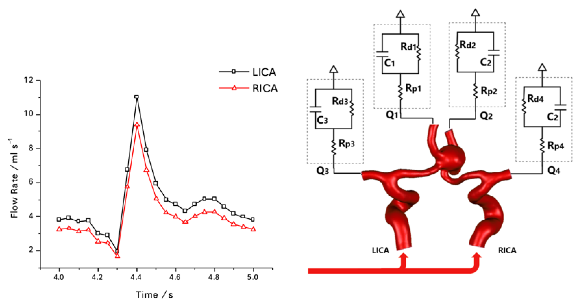
2.1. Multiscale Modeling Approach

The multiscale model in this study was composed of two components: (1) the three dimensional (3D) patient-specific ACoAA model with anterior cerebral circulation; and (2) the efferent arteries of the 3D model were coupled with zero-dimensional (0D) models that represent the distal resistance and compliance of the cerebral vascular system.
The patient-specific 3D model of anterior cerebral circulation with an ACoAA was reconstructed based on computed tomography angiography (CTA) images of a patient with ACoAA. Different degrees of stenosis, including severe stenosis (75%), moderate stenosis (50%) and mild stenosis (15%), were artificially modeled and inserted into the left ICA (LICA) of the 3D model to represent the revascularization progress, and the non-stenotic model served as the post-operative control (Figure 1).
According to the North American Symptomatic Carotid Endarterectomy Trial (NASCET) [26], the definition of stenosis degree was given as Equation (1).
S = ( 1 d s d n ) × 100 %
where S is the stenosis degree, d s is the ICA lumen diameter of the stenosis segment and d n is the ICA lumen diameter of the normal segment. To compute the d n , the cross-sectional area of the distal joints of stenosis models and the patient-specific model were calculated in MIMICS software (Materialise Inc., Leuven, Belgium) first, then the d n could be calculated from the equation of the circle area.
The blood flow in arteries was assumed to be incompressible Newtonian fluid. The 3D flow domain was governed by the mass conservation equation (Equation (2)) and unsteady Navier–Stokes equation (Equation (3))
· V = 0
ρ ( V t + ( V · V ) ) = p + μ 2 V
where ρ is the blood density, V is the velocity vector, p is the pressure and μ is the dynamic viscosity. The arterial wall was assumed as rigid for the 3D model and no-slip wall boundary conditions were imposed at the wall boundary. The dynamic viscosity and density of the blood were 0.004 Pa·s and 1060 kg/cm3, respectively.
Due to the limited resolution of clinical imaging techniques and restricted computational resources, 3D modeling of the entire cerebral circulation is still a challenge. Alternatively, the 0D Windkessel model has been extensively utilized in hemodynamics studies of the cerebral vascular system. In the 0D model, a set of lumped parameters were set to represent the arterial tree distal to their 3D parental vessel. The lumped parameters including proximal resistance (Rp), compliance (C) and distal resistance (Rd), reflect the proximal viscous resistance, arterial wall elasticity and the resistance of the capillaries and venous circulation, respectively. Equation (4) gives the differential description of the 0D model.
Q i n = C d d t ( P i n ( Q i n R p + P c ) ) + P i n ( Q i n R p + P o u t ) R d
where Q i n , P i n and P o u t are the proximal flow rate, proximal pressure and terminal pressure of the 0D model, respectively. Table 1 listed the values of lumped parameters.
To set matching conditions in the stenotic cases, the volumetric flow rates at the inlets were adjusted based on the stenosis degree to maintain the physiological pressure level. The pressure was maintained in all the cases studied. Figure 2 illustrates the scheme of boundary conditions.
All the models were discretized into tetrahedral elements. To capture the near-wall flow features, three layers of boundary prism boundary layers were generated on the arterial wall. To avoid the errors caused by discretization, mesh independent analyses were conducted. In the mesh independency study, the temporal-averaged volumetric flow rates of each efferent artery in the non-stenotic case were obtained under element numbers of 320,000, 400,000, 510,000, 690,000 and 900,000, respectively. Differences of flow rates at each outlet within 1% from the finest mesh was set as the convergence criterion. When the element number was higher than 690,000, the flow rates at all outlets became stable (Figure 3).
Finally, the model was discretized into approximately 690,000 elements (Figure 4). The governing equations of the 0D/3D couple models were solved in an open-source solver (SimVascular, ).

2.2. Data Analysis

The simulation results were post-processed in ParaView (Kitware, Inc., Clifton Park, NY, USA). The velocity distributions in all the cases were calculated and visualized. Based on which, the following hemodynamics parameters associated with rupture in ACoAA before and after the revascularization was compared.
WSS: The WSS was calculated from Equation (5), which represents the frictional force on the arterial wall that exerted the blood flow:
τ w = μ ( u y ) y = 0
where τ w is the WSS, μ is the dynamic viscosity, u is the velocity and y is the distance from the wall.
Time-averaged WSS (TAWSS): The TAWSS was calculated by integrating the WSS magnitude over a cardiac cycle (Equation (6)):
T A W S S = 1 T 0 T | τ w | d t
where T is the cardiac cycle.
OSI: OSI represents the directional changes of WSS within a cardiac cycle [27]. Equation (7) gives the definition of OSI:
O S I = 1 2 ( 1 | 0 T τ w d t | 0 T | τ w | d t )
Relative residence time (RRT): RRT is mathematically defined according to Equation (8), and represents the residence time of blood near the wall [28].
R R T = 1 ( 1 2 O S I ) × T A W S S

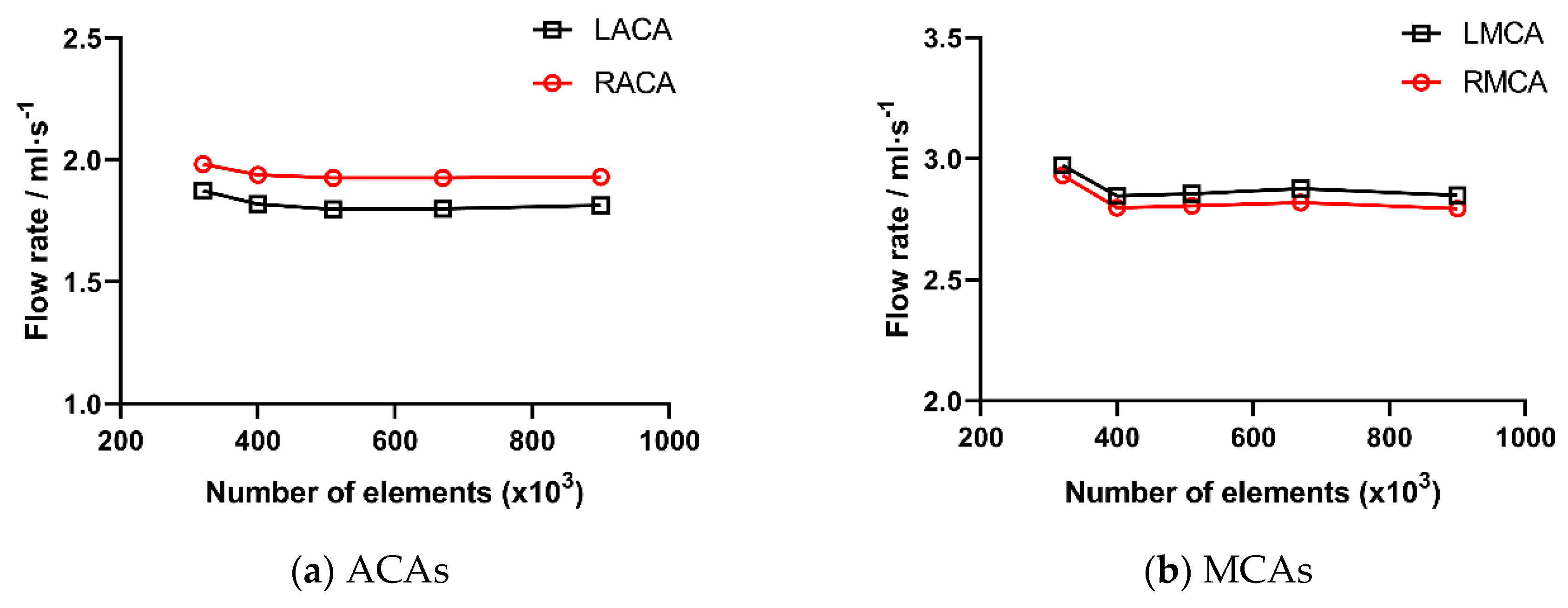
2.3. Validation of Numerical Methods

The numerical scheme utilized in this study has been widely adopted in disease evaluation and surgical planning scenarios. Various simulation results on the cardiovascular system have been validated through in vivo and in vitro measurements [29]. The validation of this study was performed by comparing the temporal-averaged efferent flow rates in the non-stenotic case with the results from the in vitro and in vivo measurements (Table 2). The blood flow in bilateral anterior cerebral arteries (ACAs) and middle cerebral arteries (MCAs) agree well with data from the literature. Therefore, the current computational model can be validated to some extent and is capable of providing physiologically significant results.

3. Results

3.1. The Impact of Revascularization on the CBF

In the severe stenosis case, the temporal-averaged flow rate over a cardiac cycle was 1.18 mL/s, which is 75.92% lower than that of the healthy side. With the stenosis degree reduction, the blood flow from the affected side increased gradually. The symmetrical CBF was finally achieved after the removal of stenosis (Table 2).

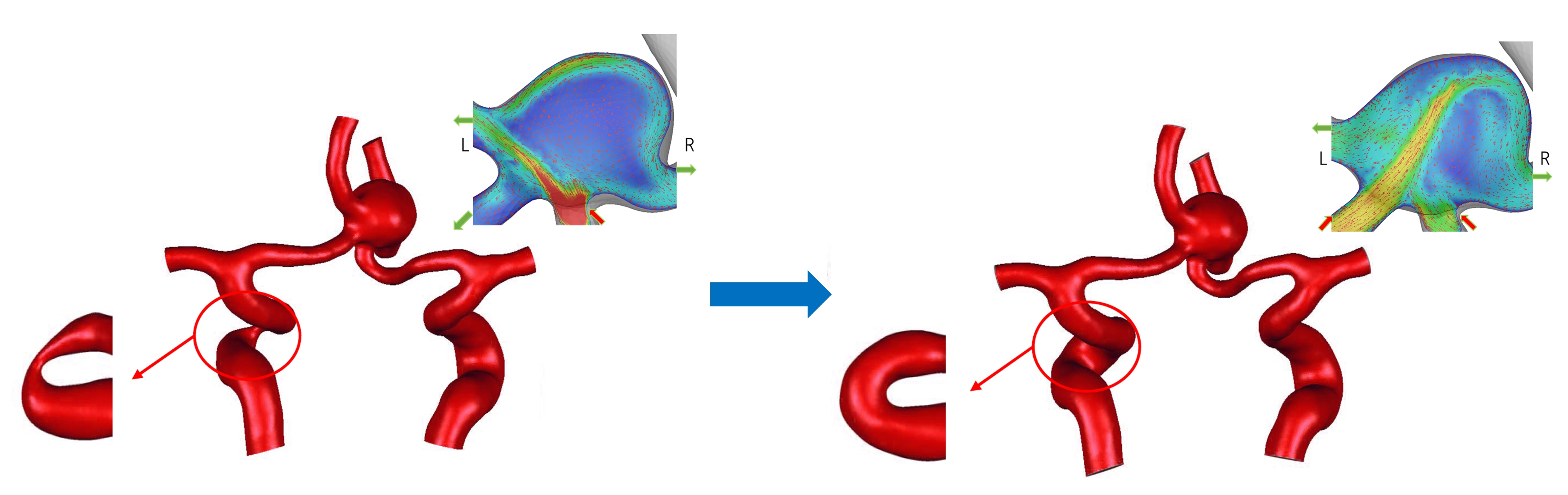
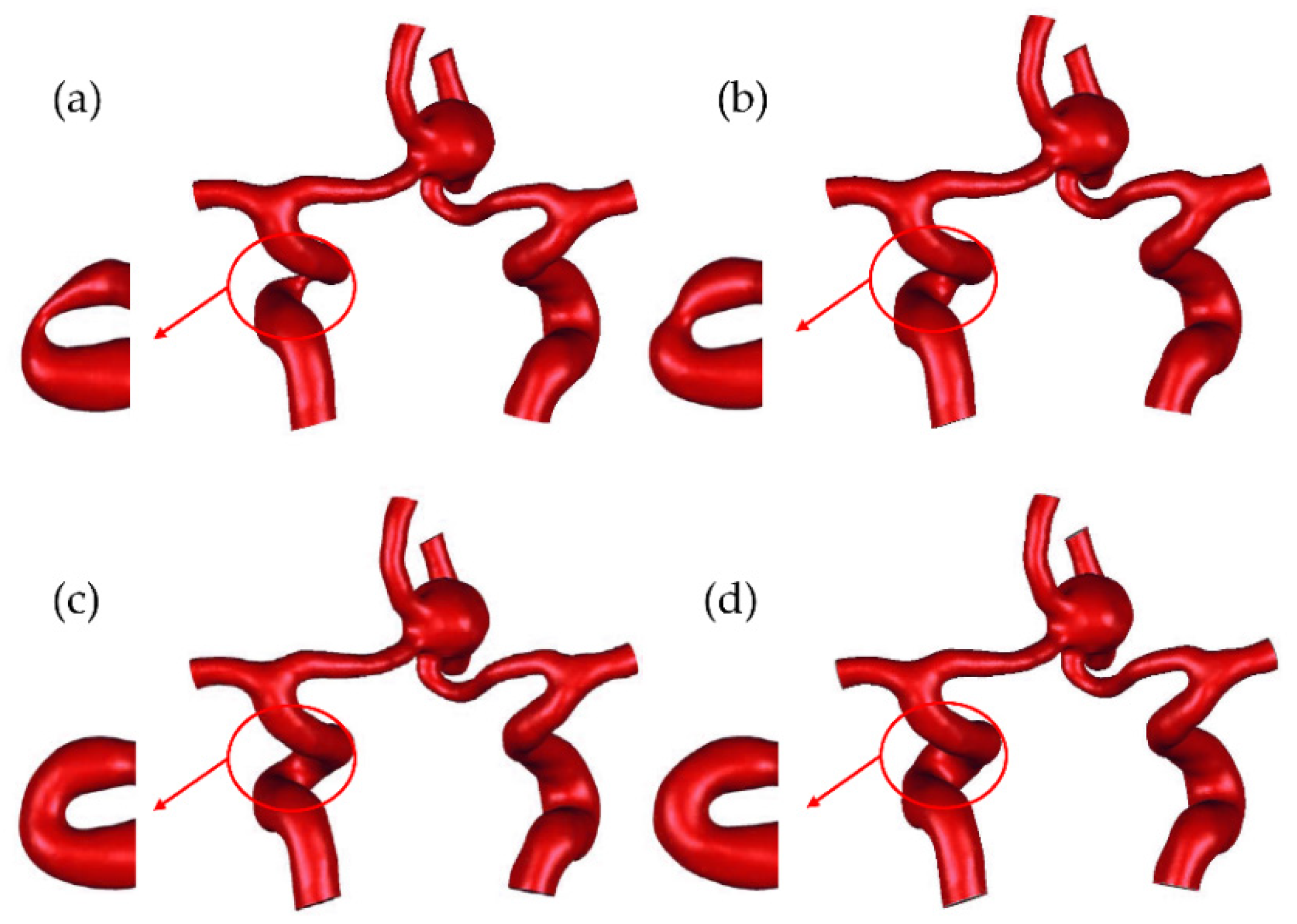
3.2. The Impact of Revascularization on Flow Patterns

The velocity fields in the central ACoAA at the peak systolic are shown in Figure 2. In the severe stenosis case, the blood from the healthy side supplied bilateral ACAs, and the reversed flow in the affected proximal segment of ACA (ACA-A1) was observed. Due to the asymmetrical blood supply, the eccentric jet from the healthy ACA-A1 induced an impinge area at the ACoAA neck (Figure 5a). Along with the decreasing stenosis degree, blood flow from the bilateral ACA-A1 confluenced in the ACoAA and created a jet impinge towards the tip of the aneurysm dome (Figure 5b).
The streamline in the ACoAA dome (Figure 5c,d) further illustrated the change of three-dimensional (3D) flow patterns caused by the variations of stenosis degree. In the severe stenosis case, clockwise helical flow generated by right anterior cerebral artery (RACA) blood supply dominated the ACoAA dome, which was featured by a single vortex and the vortex structure did not vary with time (Figure 5c). With the decreasing stenosis degree, the helical flow became more complex as the results of the confluence of ACA-A1 flowed, and finally formed two reversed helical vortices in the ACoAA dome (Figure 5d). Additionally, time-varying vortex structures were found in the non-stenotic case.

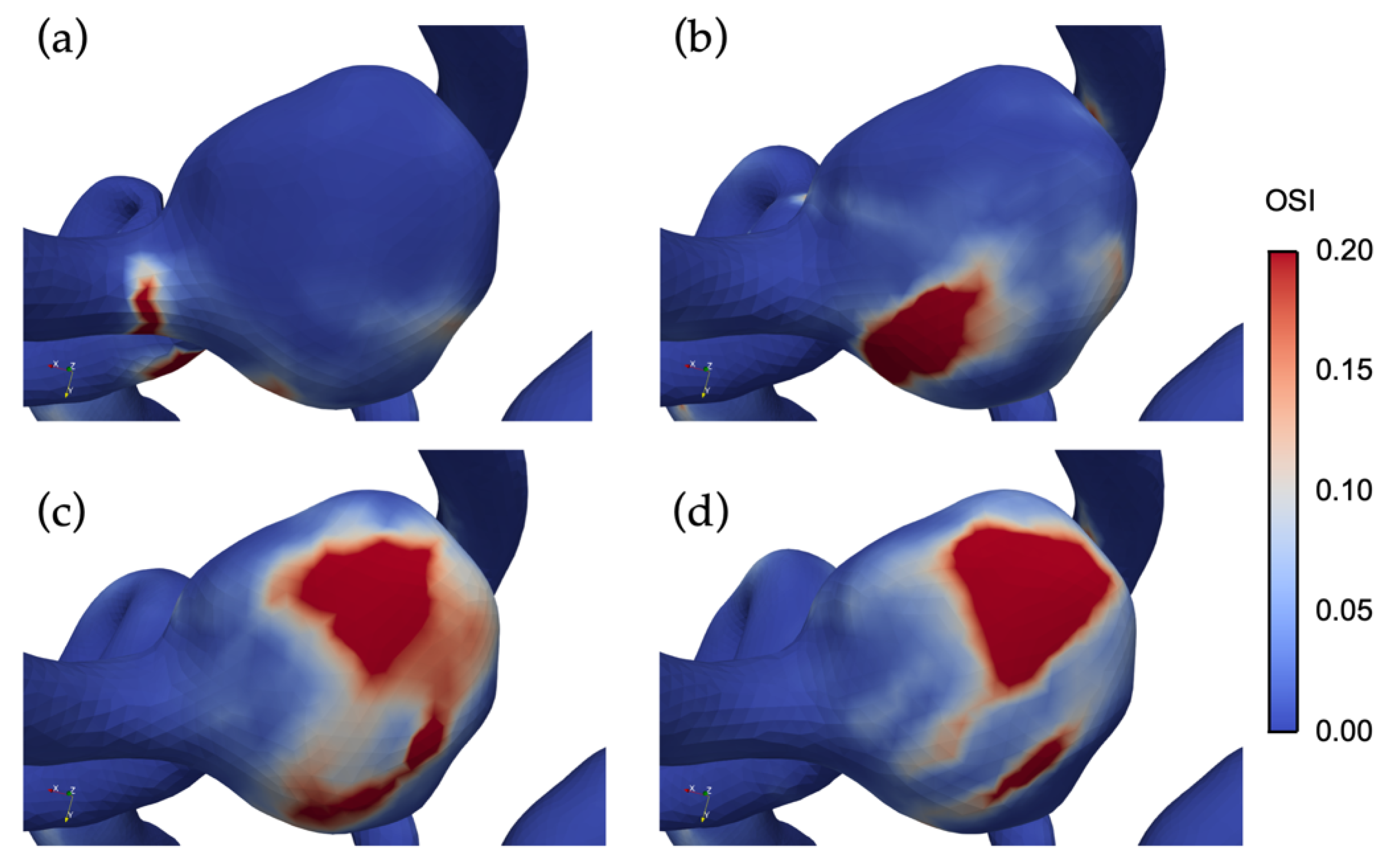
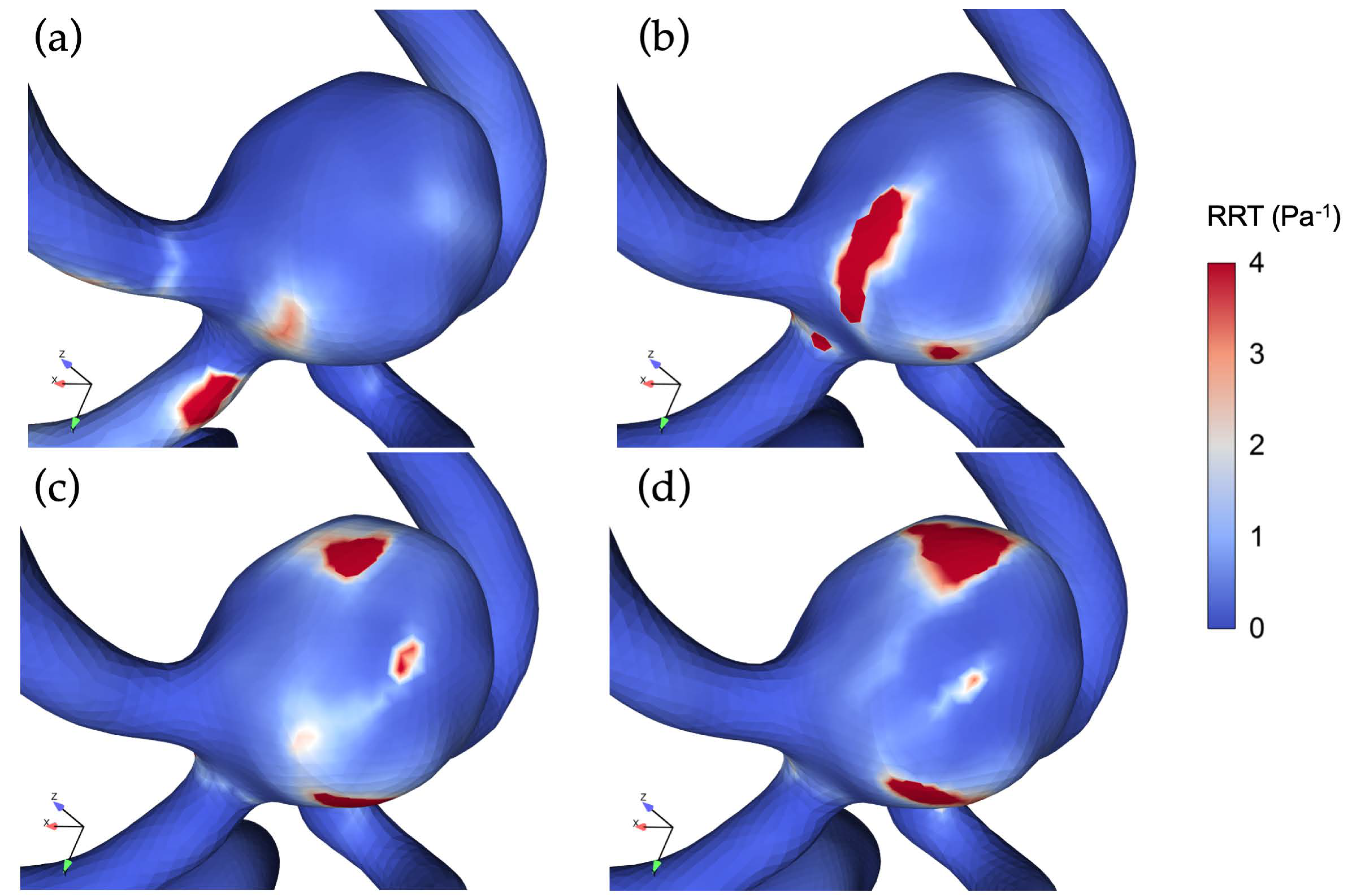
3.3. The Impact of Revascularization on the Hemodynamics Parameters

Figure 6 shows the impact of revascularization on the WSS distributions in the ACoAA. With the reduction of LICA stenosis degree, the high WSS region shifted from the left of the ACoAA dome towards the top, and the WSS magnitude on the dome’s anterior region elevated as well.
The TAWSS distributions of the cases are shown in Figure 7. The decreasing stenosis degree resulted in a reduction of overall TAWSS level and maximum TAWSS on the dome of the ACoAA.
Table 3 listed the low TAWSS (<1.5 Pa) [27,34,35,36,37] and high TAWSS (>7 Pa) [38,39,40,41] areas on the ACoAA dome. Compared with the sever stenosis case, a larger low TAWSS area and smaller high TAWSS area were observed in the case of reduced stenosis degree. The areas of low WSS and high WSS regions in the non-stenotic case were 32% larger and 67.6% smaller than that of the severe stenosis situation, respectively.
Table 4 lists the specific magnitudes of the space-averaged TAWSS and maximum TAWSS on the ACoAA dome. In the non-stenotic case, the space-averaged TAWSS and maximum TAWSS magnitudes were 48.29% and 67.42% lower than that of the severe stenosis case, respectively.
Figure 8 illustrated the OSI distributions on the ACoAA under different stenosis degrees. In the severe stenosis case, only small regions of high OSI (>0.2) were observed at the ACoAA neck of the affected side. With the decreasing stenosis degree, the high OSI regions migrated towards the ACoAA tip.
Meanwhile, the blood supply from the affected side restored gradually with the decreasing LICA stenosis degree. The confluence of bilateral blood flow in the ACoAA resulted in more complex flow patterns, which elevated the flow instability and led to an increase in high OSI area as well as the average OSI magnitude on the ACoAA dome. The high OSI area and space-averaged OSI magnitude on the ACoAA dome of the non-stenotic case were 34 times and 2.85 times larger than that of the severe stenosis case, respectively. The space-averaged OSI magnitudes on the ACoAA dome of all cases were given in Table 5.
Figure 9 illustrated RRT distribution on the ACoAA for each of the four cases. An elevation of the maximum RRT and space-averaged RRT on the ACoAA dome with the decreased stenosis degree was observed. Meanwhile, the high RRT region migrates from the ACoAA neck towards the tip.
Table 6 lists the specific values of maximum and space-averaged RRT on the ACoAA dome of all cases.

4. Discussion

This study indicates that in the case of concomitant ACoAA and unilateral ICA stenosis, complex changes of hemodynamics characteristics in the ACoAA occurs after the revascularization of stenosis. As far as we know, this is the first investigation that reveals the acute hemodynamics impacts of unilateral ICA revascularization on the distal ACoAA by using a 0D/3D computational fluid dynamics (CFD) scheme.

4.1. Modeling Considerations

The ACoAA is a vital collateral pathway of the circle of Willis as well as a preferential site of the IA [42]. Inter-hemispheric blood flow through the ACoAA and the reversed blood supply in the ACA-A1 provided critical collateral blood supply to the anterior cerebral circulation when unilateral ICA stenosis occurred [24,43]. Our previous studies have shown that in the situation of PCoA absence, the collateral flow in ACoAA changes non-linearly with the unilateral ICA stenosis degree due to the collateral mechanism [24,25]. Therefore, instead of considering the region of UIAs alone in the computational domain [44,45,46], modeling the whole anterior circulation would be more appropriate to provide better insight into the hemodynamics change in ACoAA during ICA revascularization.
The proper selection of BCs in hemodynamics simulations is essential to obtain physiologically significance results. In literature, both steady and pulsatile volumetric flow rates were usually defined as inlet BC [47]. Although the steady-state simulations were regarded as a quick alternative to transient simulations in the previous study [24,48], their incapability of providing temporal hemodynamic parameters limited their applications. Hence, transient simulations were adopted in this study, and the physiological volumetric ICA flow profiles from a 4D-MRI of a healthy patient were imposed at the afferents of the non-stenotic post-operative computational model. At the outlets of the model, 0D lumped parameter models were coupled with the efferent arteries of a 3D computational domain in the current study, in which, the compliances of large arteries and resistance of distal capillaries were simulated by using the lumped parameter method. Compared with the widely adopted free outflow conditions, the 0D/3D coupled outlet boundaries are capable of reflecting the influence of the downstream vasculature outside the 3D computational region and provide an effective prediction of velocity fields and pressure-flow relationship [29,44,49,50].

4.2. Impacts of Unilateral ICA Revascularization on ACoAA Flow Patterns

Our results showed that in the sever stenotic case, the skewed inflow jet from the healthy side impinged the contralateral aneurysm neck due to the asymmetrical blood supply and formed a single vortex that rotated towards the posterior of the ACoAA. Along with the relief of ICA stenosis, the flow pattern in the ACoAA became more complex. As the blood supply from the ACA-A1 of the affected side restored, the inflow jet moved towards the tip of the ACoAA. Meanwhile, the confluence of bilateral ACA-A1 flow formed two recirculation zones that vary with the cardiac cycle.
Several investigations have shown that such complex flow patterns play critical roles in aneurysm rupture via inflammatory remodeling of the aneurysm wall [38,40,51,52,53]. Xiang et al. analyzed 119 aneurysms and found that complex flow patterns appeared in more than 60% of ruptured aneurysms, which were featured by multiple vortices [51]. In contrast, most of the UIAs only presented a single vortex [51]. Similar observations were reported by some recent studies [54,55]. These phenomena indicate a potential increase in rupture risk of ACoAA after revascularization.

4.3. Impacts of Unilateral ICA Revascularization on ACoAA Hemodynamics Characteristics

Significant correlations between IA’s rupture status and derivatives of WSS have been highlighted by several studies [14,27,35,36,38,39,40,56,57]. Under the pulsatile flow conditions, TAWSS generally characterizes the overall WSS levels. The normal TAWSS magnitudes in arteries range from 1.5 to 7 Pa, whereas it could reach 1 to 22 Pa in IAs [58]. Despite both aberrantly high (>7 Pa) [38,39,40,41] and low TAWSS (<1.5 Pa) [27,34,35,36,37], they have been reported to contribute to the IA rupture via complex mechanobiological mechanisms [14,17]; associations between low TAWSS and the risk of rupture of large IAs (>5 mm) have been identified by some of the latest investigations [14,15,59]. Additionally, high OSI (>0.2), which reflects the elevated local flow instability, was also considered as an important factor in the rupture of IAs by upregulating inflammatory cell-mediated destructive remodeling [14,56,60,61,62]. Moreover, this corresponds with the lower and stronger oscillatory WSS and the prolonged RRT has been linked with higher rupture risk as well [15].
Our current results showed that besides the flow patterns, the revascularization of unilateral ICA also greatly affected the magnitudes and distributions of hemodynamics characteristics in the ACoAA. The main findings include: (1) the region of low TAWSS elevated with the decreasing unilateral ICA stenosis degree; (2) the overall OSI magnitude as well as high OSI area on the ACoAA increased with the decreasing LICA stenosis degree, which is mainly due to the elevated flow complexity that was induced by confluence of bilateral flow from ACA-A1; (3) the RRT was prolonged in the non-stenotic case. These data further support that revascularization procedures would lead to an elevated rupture risk in the cases studied.

4.4. Limitations

The current study has some limitations. First and foremost, the rigid wall assumption constrained the capability of predicting accurate WSS distribution. Several studies have reported that the neglecting of IAs wall elasticity would lead to an overestimation of WSS [63,64,65,66]. However, the quantitative impacts of wall elasticity on WSS distribution is unclear due to the difficulties in obtaining the patient-specific aneurysm wall properties from in vivo measurements. In addition, more samples should be included in future studies to systemically evaluate the impacts of space characteristics of ACoAAs on flow characteristics. Furthermore, the blood was simplified as a Newtonian fluid in the present study. The effect of rheological models on flow characteristics in IAs has been discussed in several studies [65]. Even though their impacts remain inconsistent [67,68,69], some recent studies showed that the influence of using the Newtonian model on hemodynamics characteristics is small [70,71].

5. Conclusions

The revascularization of unilateral ICA would significantly affect the hemodynamics characteristics in large ACoAA. CFD analysis of the postoperative hemodynamics parameters may be useful to evaluate the rupture risk and benefit the preoperative management of patients with concomitant ACoAA and unilateral ICA stenosis.

Author Contributions

Conceptualization, G.-Y.Z.; methodology, Y.W.; investigation, Y.W., G.-Y.Z.; resources, Q.Y.; writing—original draft preparation, G.-Y.Z. and Y.W.; writing—review and editing, C.-F.Y. and G.-Y.Z.; visualization, Y.-L.S.; supervision, G.-Y.Z.; project administration, Q.Y.; funding acquisition, G.-Y.Z.

Funding

This research was funded by the National Natural Science Foundation of China (NSFC) (11802227), China Postdoctoral Science Foundation Grant (2016M600781) and the Fundamental Research Funds for the Central Universities (XJJ2017032).

Acknowledgments

The authors would like to acknowledge Alison Marsden and her team for developing the open-source software SimVacsular.

Conflicts of Interest

The authors declare no conflicts of interest. The funders had no role in the design of the study; in the collection, analyses, or interpretation of data; in the writing of the manuscript, or in the decision to publish the results.

References

  1. Khan, U.A.; Thapar, A.; Shalhoub, J.; Davies, A.H. Risk of intracerebral aneurysm rupture during carotid revascularization. J. Vasc. Surg. 2012, 56, 1739–1747. [Google Scholar] [CrossRef] [PubMed] [Green Version]
  2. Yang, X.; Lu, J.; Wang, J.; Wang, L.; Qi, P.; Hu, S.; Chen, K.; Wang, D. A clinical study and meta-analysis of carotid stenosis with coexistent intracranial aneurysms. J. Clin. Neurosci. 2018, 52, 41–49. [Google Scholar] [CrossRef] [PubMed]
  3. Cvetic, V.; Dragas, M.; Colic, M.; Vukasinovic, I.; Radmili, O.; Ilic, N.; Koncar, I.; Bascarevic, V.; Ristanovic, N.; Davidovic, L. Simultaneous Endovascular Treatment of Tandem Internal Carotid Lesions. Vasc. Endovasc. Surg. 2016, 50, 359–362. [Google Scholar] [CrossRef] [PubMed]
  4. Castro, E.; Villoria, F.; Fortea, F.; Carrera, J.; Mateo, O.; Sanchez-Alarcos, S.; Reparaz, L. Simultaneous Cerebral Aneurysms and Carotid Disease Should the Symptomatic Lesion always be the first to be Treated? Interv. Neuroradiol. 2003, 9, 213–218. [Google Scholar] [CrossRef] [PubMed]
  5. Bederson, J.B.; Awad, I.A.; Wiebers, D.O.; Piepgras, D.; Haley, E.C.; Brott, T.; Hademenos, G.; Chyatte, D.; Rosenwasser, R.; Caroselli, C. Recommendations for the management of patients with unruptured intracranial aneurysms: A statement for healthcare professionals from the Stroke Council of the American Heart Association. Circulation 2000, 102, 2300–2308. [Google Scholar] [CrossRef]
  6. Hartmann, M.; Weber, R.; Zoubaa, S.; Schranz, C.; Knauth, M. Fatal subarachnoid hemorrhage after carotid stenting. J. Neuroradiol. 2004, 31, 63–66. [Google Scholar] [CrossRef]
  7. Wiebers, D.O.; Whisnant, J.P.; Huston, J.; Meissner, I.; Brown, R.D.; Piepgras, D.G.; Forbes, G.S.; Thielen, K.; Nichols, D.; O’Fallon, W.M.; et al. Unruptured intracranial aneurysms: Natural history, clinical outcome, and risks of surgical and endovascular treatment. Lancet (Lond. Engl.) 2003, 362, 103–110. [Google Scholar] [CrossRef]
  8. Kappelle, L.J.; Eliasziw, M.; Fox, A.J.; Barnett, H.J.M. Small, unruptured intracranial aneurysms and management of symptomatic carotid artery stenosis. Neurology 2000, 55, 307–309. [Google Scholar] [CrossRef]
  9. Tallarita, T.; Sorenson, T.J.; Rinaldo, L.; Oderich, G.S.; Bower, T.C.; Meyer, F.B.; Lanzino, G. Management of carotid artery stenosis in patients with coexistent unruptured intracranial aneurysms. J. Neurosurg. 2019, 1–4. [Google Scholar] [CrossRef]
  10. Suh, B.-Y.; Yun, W.-S.; Kwun, W.-H. Carotid artery revascularization in patients with concomitant carotid artery stenosis and asymptomatic unruptured intracranial artery aneurysm. Ann. Vasc. Surg. 2011, 25, 651–655. [Google Scholar] [CrossRef]
  11. Uchida, H.; Endo, H.; Fujimura, M.; Endo, T.; Niizuma, K.; Tominaga, T. Intra-operative hemorrhage due to hyperperfusion during direct revascularization surgery in an adult patient with moyamoya disease: A case report. Neurosurg. Rev. 2017, 40, 679–684. [Google Scholar] [CrossRef]
  12. Riphagen, J.H.; Bernsen, H.J.J.A. Rupture of an intracerebral aneurysm after carotid endarterectomy: A case report. Acta Neurol. Belg. 2009, 109, 314–316. [Google Scholar]
  13. Batjer, H.; Mickey, B.; Samson, D. Enlargement and rupture of distal basilar artery aneurysm after iatrogenic carotid occlusion. Neurosurgery 1987, 20, 624–628. [Google Scholar] [CrossRef]
  14. Meng, H.; Tutino, V.M.; Xiang, J.; Siddiqui, A. High WSS or Low WSS? Complex interactions of hemodynamics with intracranial aneurysm initiation, growth, and rupture: Toward a unifying hypothesis. Am. J. Neuroradiol. 2014, 35, 1254–1262. [Google Scholar] [CrossRef]
  15. Cebral, J.R.; Detmer, F.; Chung, B.J.; Choque-Velasquez, J.; Rezai, B.; Lehto, H.; Tulamo, R.; Hernesniemi, J.; Niemela, M.; Yu, A.; et al. Local hemodynamic conditions associated with focal changes in the intracranial aneurysm wall. Am. J. Neuroradiol. 2019, 40, 510–516. [Google Scholar]
  16. Liang, L.; Steinman, D.A.; Brina, O.; Chnafa, C.; Cancelliere, N.M.; Pereira, V.M. Towards the Clinical utility of CFD for assessment of intracranial aneurysm rupture—A systematic review and novel parameter-ranking tool. J. Neurointerv. Surg. 2019, 11, 153–158. [Google Scholar] [CrossRef]
  17. Etminan, N.; Rinkel, G.J. Unruptured intracranial aneurysms: Development, rupture and preventive management. Nat. Rev. Neurol. 2016, 12, 699–713. [Google Scholar] [CrossRef]
  18. Bacigaluppi, S.; Piccinelli, M.; Antiga, L.; Veneziani, A.; Passerini, T.; Rampini, P.; Zavanone, M.; Severi, P.; Tredici, G.; Zona, G.; et al. Factors affecting formation and rupture of intracranial saccular aneurysms. Neurosurg. Rev. 2014, 37, 1–14. [Google Scholar] [CrossRef]
  19. Brinjikji, W.; Chung, B.J.; Jimenez, C.; Putman, C.; Kallmes, D.F.; Cebral, J.R. Hemodynamic differences between unstable and stable unruptured aneurysms independent of size and location: A pilot study. J. Neurointerv. Surg. 2017, 9, 376–380. [Google Scholar] [CrossRef]
  20. Dhar, S.; Tremmel, M.; Mocco, J.; Kim, M.; Yamamoto, J.; Siddiqui, A.H.; Hopkins, L.N.; Meng, H. Morphology parameters for intracranial aneurysm rupture risk assessment. Neurosurgery 2008, 63, 185–196; discussion 196–197. [Google Scholar] [CrossRef]
  21. Alfano, J.M.; Kolega, J.; Natarajan, S.K.; Xiang, J.; Paluch, R.A.; Levy, E.I.; Siddiqui, A.H.; Meng, H. Intracranial Aneurysms Occur More Frequently at Bifurcation Sites That Typically Experience Higher Hemodynamic Stresses. Neurosurgery 2013, 73, 497–505. [Google Scholar] [CrossRef]
  22. Rinkel, G.J.E.; Djibuti, M.; Algra, A.; van Gijn, J. Prevalence and Risk of Rupture of Intracranial Aneurysms. Stroke 1998, 29, 251–256. [Google Scholar] [CrossRef] [Green Version]
  23. Castro, M.A.; Putman, C.M.; Cebral, J.R. Patient-Specific Computational Modeling of Cerebral Aneurysms with Multiple Avenues of Flow from 3D Rotational Angiography Images. Acad. Radiol. 2006, 13, 811–821. [Google Scholar] [CrossRef]
  24. Zhu, G.; Yuan, Q.; Yang, J.; Yeo, J.H. The role of the circle of Willis in internal carotid artery stenosis and anatomical variations: A computational study based on a patient-specific three-dimensional model. Biomed. Eng. Online 2015, 14, 107. [Google Scholar] [CrossRef]
  25. Zhu, G.Y.; Yuan, Q.; Yang, J.; Yeo, J.H. Experimental study of hemodynamics in the Circle of Willis. Biomed. Eng. Online 2015, 14, S10. [Google Scholar] [CrossRef]
  26. NASCET. North american symptomatic sarotid endarterectomy trial. Methods, patient characteristics, and progress. Stroke 1991, 22, 711–720. [Google Scholar] [CrossRef]
  27. Miura, Y.; Ishida, F.; Umeda, Y.; Tanemura, H.; Suzuki, H.; Matsushima, S.; Shimosaka, S.; Taki, W. Low Wall Shear Stress Is Independently Associated With the Rupture Status of Middle Cerebral Artery Aneurysms. Stroke 2013, 44, 519–521. [Google Scholar] [CrossRef] [Green Version]
  28. Catalán-Echeverría, B.; Kelly, M.; Peeling, L.; Bergstrom, D.; Chen, X.; Malvè, M. CFD-Based Comparison Study of a New Flow Diverting Stent and Commercially-Available Ones for the Treatment of Cerebral Aneurysms. Appl. Sci. 2019, 9, 1341. [Google Scholar] [CrossRef]
  29. Updegrove, A.; Wilson, N.M.; Merkow, J.; Lan, H.; Marsden, A.L.; Shadden, S.C. SimVascular: An Open Source Pipeline for Cardiovascular Simulation. Ann. Biomed. Eng. 2017, 45, 525–541. [Google Scholar] [CrossRef]
  30. Enzmann, D.R.; Ross, M.R.; Marks, M.P.; Pelc, N.J. Blood flow in major cerebral arteries measured by phase-contrast cine MR. Am. J. Neuroradiol. 1994, 15, 123–129. [Google Scholar]
  31. Zhao, M.; Amin-Hanjani, S.; Ruland, S.; Curcio, A.P.; Ostergren, L.; Charbel, F.T. Regional cerebral blood flow using quantitative MR angiography. Am. J. Neuroradiol. 2007, 28, 1470–1473. [Google Scholar] [CrossRef] [PubMed]
  32. Cieslicki, K.; Ciesla, D. Investigations of flow and pressure distributions in physical model of the circle of Willis. J. Biomech. 2005, 38, 2302–2310. [Google Scholar] [CrossRef] [PubMed]
  33. Zarrinkoob, L.; Ambarki, K.; Wåhlin, A.; Birgander, R.; Eklund, A.; Malm, J. Blood flow distribution in cerebral arteries. J. Cereb. Blood Flow Metab. 2015, 35, 648–654. [Google Scholar] [CrossRef] [PubMed]
  34. Skodvin, T.Ø.; Evju, Ø.; Helland, C.A.; Isaksen, J.G. Rupture prediction of intracranial aneurysms: A nationwide matched case-control study of hemodynamics at the time of diagnosis. J. Neurosurg. 2018, 129, 854–860. [Google Scholar] [CrossRef] [PubMed]
  35. Kadasi, L.M.; Dent, W.C.; Malek, A.M. Colocalization of thin-walled dome regions with low hemodynamic wall shear stress in unruptured cerebral aneurysms. J. Neurosurg. 2013, 119, 172–179. [Google Scholar] [CrossRef] [Green Version]
  36. Shojima, M. Magnitude and Role of Wall Shear Stress on Cerebral Aneurysm. Computational Fluid Dynamic Study of 20 Middle Cerebral Artery Aneurysms. Stroke 2004, 35, 2500–2505. [Google Scholar] [CrossRef] [PubMed]
  37. Zhang, X.; Yao, Z.-Q.; Karuna, T.; He, X.-Y.; Wang, X.-M.; Li, X.-F.; Liu, W.-C.; Li, R.; Guo, S.-Q.; Chen, Y.-C.; et al. The role of wall shear stress in the parent artery as an independent variable in the formation status of anterior communicating artery aneurysms. Eur. Radiol. 2019, 29, 689–698. [Google Scholar] [CrossRef]
  38. Cebral, J.R.; Mut, F.; Weir, J.; Putman, C.M. Association of hemodynamic characteristics and cerebral aneurysm rupture. Am. J. Neuroradiol. 2011, 32, 264–270. [Google Scholar] [CrossRef]
  39. Cebral, J.R.; Mut, F.; Weir, J.; Putman, C. Quantitative Characterization of the Hemodynamic Environment in Ruptured and Unruptured Brain Aneurysms. Am. J. Neuroradiol. 2011, 32, 145–151. [Google Scholar] [CrossRef]
  40. Castro, M.A.; Putman, C.M.; Sheridan, M.J.; Cebral, J.R. Hemodynamic Patterns of Anterior Communicating Artery Aneurysms: A Possible Association with Rupture. Am. J. Neuroradiol. 2009, 30, 297–302. [Google Scholar] [CrossRef] [Green Version]
  41. Cebral, J.R.; Duan, X.; Gade, P.S.; Chung, B.J.; Mut, F.; Aziz, K.; Robertson, A.M. Regional Mapping of Flow and Wall Characteristics of Intracranial Aneurysms. Ann. Biomed. Eng. 2016, 44, 3553–3567. [Google Scholar] [CrossRef] [PubMed] [Green Version]
  42. Jou, L.-D.; Lee, D.H.; Mawad, M.E. Cross-flow at the anterior communicating artery and its implication in cerebral aneurysm formation. J. Biomech. 2010, 43, 2189–2195. [Google Scholar] [CrossRef] [PubMed]
  43. Liebeskind, D.S. Collateral circulation. Stroke 2003, 34, 2279–2284. [Google Scholar] [CrossRef] [PubMed]
  44. Liang, F.; Oshima, M.; Huang, H.; Liu, H.; Takagi, S. Numerical Study of Cerebroarterial Hemodynamic Changes Following Carotid Artery Operation: A Comparison Between Multiscale Modeling and Stand-Alone Three-Dimensional Modeling. J. Biomech. Eng. 2015, 137, 101011. [Google Scholar] [CrossRef] [PubMed]
  45. Valencia, A.; Torres, F. Effects of Hypertension and Pressure Gradient in A Human Cerebral Aneurysm Using Fluid Structure Interaction simulations. J. Mech. Med. Biol. 2017, 17, 1750018. [Google Scholar] [CrossRef]
  46. Zhang, Y.; Jing, L.; Zhang, Y.; Liu, J.; Yang, X. Low wall shear stress is associated with the rupture of intracranial aneurysm with known rupture point: Case report and literature review. BMC Neurol. 2016, 16, 231. [Google Scholar] [CrossRef]
  47. Russin, J.; Babiker, H.; Ryan, J.; Rangel-Castilla, L.; Frakes, D.; Nakaji, P. Computational Fluid Dynamics to Evaluate the Management of a Giant Internal Carotid Artery Aneurysm. World Neurosurg. 2015, 83, 1057–1065. [Google Scholar] [CrossRef]
  48. Karmonik, C.; Diaz, O.; Klucznik, R.; Grossman, R.G.; Zhang, Y.J.; Britz, G.; Lv, N.; Huang, Q. Quantitative comparison of hemodynamic parameters from steady and transient CFD simulations in cerebral aneurysms with focus on the aneurysm ostium. J. Neurointerv. Surg. 2015, 7, 367–372. [Google Scholar] [CrossRef]
  49. Pewowaruk, R.; Roldán-Alzate, A. 4D Flow MRI Estimation of Boundary Conditions for Patient Specific Cardiovascular Simulation. Ann. Biomed. Eng. 2019, 47, 1786–1798. [Google Scholar] [CrossRef]
  50. Vignon, I.E.; Taylor, C.A. Outflow boundary conditions for one-dimensional finite element modeling of blood flow and pressure waves in arteries. Wave Motion 2004, 39, 361–374. [Google Scholar] [CrossRef]
  51. Xiang, J.; Natarajan, S.K.; Tremmel, M.; Ma, D.; Mocco, J.; Hopkins, L.N.; Siddiqui, A.H.; Levy, E.I.; Meng, H. Hemodynamic–Morphologic Discriminants for Intracranial Aneurysm Rupture. Stroke 2011, 42, 144–152. [Google Scholar] [CrossRef]
  52. Lee, U.Y.; Jung, J.; Kwak, H.S.; Lee, D.H.; Chung, G.H.; Park, J.S.; Koh, E.J. Wall shear stress and flow patterns in unruptured and ruptured anterior communicating artery aneurysms using computational fluid dynamics. J. Korean Neurosurg. Soc. 2018, 61, 689–699. [Google Scholar] [CrossRef]
  53. Yamaguchi, R.; Ujiie, H.; Haida, S.; Nakazawa, N.; Hori, T. Velocity profile and wall shear stress of saccular aneurysms at the anterior communicating artery. Heart Vessels 2008, 23, 60–66. [Google Scholar] [CrossRef]
  54. Fukazawa, K.; Ishida, F.; Umeda, Y.; Miura, Y.; Shimosaka, S.; Matsushima, S.; Taki, W.; Suzuki, H. Using computational fluid dynamics analysis to characterize local hemodynamic features of middle cerebral artery aneurysm rupture points. World Neurosurg. 2015, 83, 80–86. [Google Scholar] [CrossRef]
  55. Xiang, J.; Yu, J.; Snyder, K.V.; Levy, E.I.; Siddiqui, A.H.; Meng, H. Hemodynamic-morphological discriminant models for intracranial aneurysm rupture remain stable with increasing sample size. J. Neurointerv. Surg. 2016, 8, 104–110. [Google Scholar] [CrossRef]
  56. Can, A.; Du, R. Association of hemodynamic factors with intracranial aneurysm formation and rupture: Systematic review and meta-analysis. Neurosurgery 2016, 78, 510–519. [Google Scholar] [CrossRef]
  57. Le, W.-J.; Zhu, Y.-Q.; Li, M.-H.; Yan, L.; Tan, H.-Q.; Xiao, S.-M.; Cheng, Y.-S. New method for retrospective study of hemodynamic changes before and after aneurysm formation in patients with ruptured or unruptured aneurysms. BMC Neurol. 2013, 13, 166. [Google Scholar] [CrossRef]
  58. Sadasivan, C.; Fiorella, D.J.; Woo, H.H.; Lieber, B.B. Physical Factors Effecting Cerebral Aneurysm Pathophysiology. Ann. Biomed. Eng. 2013, 41, 1347–1365. [Google Scholar] [CrossRef]
  59. Varble, N.; Tutino, V.M.; Yu, J.; Sonig, A.; Siddiqui, A.H.; Davies, J.M.; Meng, H. Shared and Distinct Rupture Discriminants of Small and Large Intracranial Aneurysms. Stroke 2018, 49, 856–864. [Google Scholar] [CrossRef]
  60. Murayama, Y.; Fujimura, S.; Suzuki, T.; Takao, H. Computational fluid dynamics as a risk assessment tool for aneurysm rupture. Neurosurg. Focus 2019, 47, E12. [Google Scholar] [CrossRef] [Green Version]
  61. Jiang, P.; Liu, Q.; Wu, J.; Chen, X.; Li, M.; Li, Z.; Yang, S.; Guo, R.; Gao, B.; Cao, Y.; et al. A Novel Scoring System for Rupture Risk Stratification of Intracranial Aneurysms: A Hemodynamic and Morphological Study. Front. Neurosci. 2018, 12, 596. [Google Scholar] [CrossRef] [PubMed]
  62. Chen, H.; Selimovic, A.; Thompson, H.; Chiarini, A.; Penrose, J.; Ventikos, Y.; Watton, P.N. Investigating the Influence of Haemodynamic Stimuli on Intracranial Aneurysm Inception. Ann. Biomed. Eng. 2013, 41, 1492–1504. [Google Scholar] [CrossRef] [PubMed]
  63. Torii, R.; Oshima, M.; Kobayashi, T.; Takagi, K.; Tezduyar, T.E. Influencing factors in image-based fluid-structure interaction computation of cerebral aneurysms. Int. J. Numer. Methods Fluids 2011, 65, 324–340. [Google Scholar] [CrossRef]
  64. Bazilevs, Y.; Hsu, M.-C.; Zhang, Y.; Wang, W.; Kvamsdal, T.; Hentschel, S.; Isaksen, J.G. Computational vascular fluid-structure interaction: Methodology and application to cerebral aneurysms. Biomech. Model. Mechanobiol. 2010, 9, 481–498. [Google Scholar] [CrossRef] [PubMed]
  65. Chung, B.; Cebral, J.R. CFD for Evaluation and Treatment Planning of Aneurysms: Review of Proposed Clinical Uses and Their Challenges. Ann. Biomed. Eng. 2014, 43, 122–138. [Google Scholar] [CrossRef] [PubMed]
  66. Xu, L.; Liang, F.; Gu, L.; Liu, H. Flow instability detected in ruptured versus unruptured cerebral aneurysms at the internal carotid artery. J. Biomech. 2018, 72, 187–199. [Google Scholar] [CrossRef]
  67. Hippelheuser, J.E.; Lauric, A.; Cohen, A.D.; Malek, A.M. Realistic non-Newtonian viscosity modelling highlights hemodynamic differences between intracranial aneurysms with and without surface blebs. J. Biomech. 2014, 47, 3695–3703. [Google Scholar] [CrossRef]
  68. Fisher, C.; Rossmann, J.S. Effect of non-newtonian behavior on hemodynamics of cerebral aneurysms. J. Biomech. Eng. 2009, 131, 091004. [Google Scholar] [CrossRef]
  69. Valencia, A.; Zarate, A.; Galvez, M.; Badilla, L. Non-Newtonian blood flow dynamics in a right internal carotid artery with a saccular aneurysm. Int. J. Numer. Methods Fluids 2006, 50, 751–764. [Google Scholar] [CrossRef]
  70. Khan, M.O.; Steinman, D.A.; Valen-Sendstad, K. Non-Newtonian versus numerical rheology: Practical impact of shear-thinning on the prediction of stable and unstable flows in intracranial aneurysms. Int. J. Numer. Methods Biomed. Eng. 2017, 33, 1–10. [Google Scholar] [CrossRef]
  71. Evju, Ø.; Valen-Sendstad, K.; Mardal, K.A. A study of wall shear stress in 12 aneurysms with respect to different viscosity models and flow conditions. J. Biomech. 2013, 46, 2802–2808. [Google Scholar] [CrossRef] [PubMed]
Figure 1. Models of the anterior cerebral circulation with anterior communicating artery aneurysm (ACoAA): (a) severe stenosis (75%); (b) moderate stenosis model (50%); (c) mild stenosis model (15%); and (d) non-stenotic model.
Applsci 09 04143 g001
Figure 2. Schematic of boundary conditions.
Applsci 09 04143 g002
Figure 3. Mesh independency study results. ACAs: anterior cerebral arteries; MCAs: middle cerebral arteries.
Applsci 09 04143 g003
Figure 4. The final result of discretization.
Applsci 09 04143 g004
Figure 5. Impacts of revascularization on velocity vectors (a,b) and streamlines (c,d) in the anterior communicating artery aneurysm (ACoAA) at peak systolic. The pre-operative and post-operative results were shown in the left and right column, respectively.
Applsci 09 04143 g005
Figure 6. Impacts of revascularization on the wall shear stress (WSS) distribution of ACoAA at peak systolic.
Applsci 09 04143 g006
Figure 7. The distribution of time-averaged wall shear stress (TAWSS) on the ACoAA under different stenosis degrees: (a) non-stenotic, (b) mild stenosis, (c) moderate stenosis, (d) severe stenosis.
Applsci 09 04143 g007
Figure 8. The distribution of oscillating shear index (OSI) on the ACoAA under different degrees of stenosis: (a) non-stenotic, (b) mild stenosis, (c) moderate stenosis, (d) severe stenosis.
Applsci 09 04143 g008
Figure 9. The distribution of relative residence time (RRT) on the ACoAA under different degrees of stenosis: (a) severe stenosis, (b) moderate stenosis, (c) mild stenosis, (d) non-stenotic.
Applsci 09 04143 g009
Table 1. The values of optimal lumped parameters for the 0D model.
Rp (dyne·s/cm5)C (cm5/dyne)Rd (dyne·s/cm5)
Left Middle Cerebral Artery (LMCA)4168.216.50368 × 10−641,682.1
Right Middle Cerebral Artery (RMCA)3989.866.7944 × 10−639,898.6
Left Anterior Cerebral Artery (LACA)6304.054.30021 × 10−663,040.5
Right Anterior Cerebral Artery (RACA)5891.024.6017 × 10−658,910.2
Table 2. Comparison of blood flow in efferent arteries.
StudyVolumetric Flow Rate (mL/s)
LACARACALMCARMCA
Current Study1.811.932.852.79
Zhu et al. [24]1.391.392.782.78
Zhu et al. [25]1.341.343.263.26
Enzmann et al. [30]1.25 ± 0.171.47 ± 0.181.80 ± 0.122.12 ± 0.12
Zhao et al. [31]1.42 ± 0.431.33 ± 0.472.5 ± 0.522.42 ± 0.45
Cieslicki et al. [32]1.54 ± 0.031.56 ± 0.032.44 ± 0.052.41 ± 0.05
Zarrinkoob et al. [33]1.54 ± 0.561.68 ± 0.562.94 ± 0.422.94 ± 0.28
Table 3. Space-averaged TAWSS magnitude on the ACoAA.
CasesArea (mm2)
Low TAWSSHigh TAWSS
Severe stenosis5065
Moderate stenosis7228
Mild stenosis6918
Non-stenotic6621
Table 4. Space-averaged TAWSS magnitude on the ACoAA.
TAWSS Magnitude/Pa
Severe StenosisModerate StenosisMild StenosisNon-Stenotic
Space-averaged7.024.033.573.63
Maximum77.7740.9124.2725.34
Table 5. Space-averaged OSI magnitude on the ACoAA.
Severe StenosisModerate StenosisMild StenosisNon-Stenotic
0.0200.0350.0590.057
Table 6. Maximum and space-averaged RRT on the ACoAA.
RRT/Pa−1
Severe StenosisModerate StenosisMild StenosisNon-Stenotic
Maximum28.6358.9470.52184.82
Space-averaged0.390.670.831.14

