1. Introduction
The laser Doppler velocimeter (LDV) is a well-known equipment used to measure motions, fluid, and airflow [
1,
2,
3,
4,
5,
6]. By illuminating the flow or object with a laser and measuring the scattering caused by movement, it is possible to calculate its speed [
7,
8]. LDV is capable of providing high spatial resolution and high response speed and is characterized by non-contact measurement. In recent years, the development of the laser Doppler velocimeter has been more and more mature, and various techniques for the LDV have been explored in practical applications [
9,
10,
11,
12]. Zeyuan Kuang et al. have designed a dual-polarization fiber grating laser-based laser Doppler velocimeter and achieved a velocity measurement range of 2–37 m/s [
13]. Recently, the mode-locked laser is applied in absolute distance measurement and its precision is in the nanometer magnitude. Mohammad U. Piracha et al. utilize a train of oppositely chirped pulses to probe a fast-moving target at >91 m/s [
1]. Yan Bai et al. utilize a mode-locked laser to measure a target, whose speed is dozens of m/s, through the method of heterodyne Doppler velocimetry, with the measurement error being only 0.4 m/s [
14]. However, these technologies are all used for the field of high-speed measurement. Hongbin Zhu et al. have exploited a birefringent dual-frequency laser Doppler velocimeter in the low-velocity area [
15]. In their work, the performance of the developed LDV is evaluated through velocity measurements with a range of 0.159 mm/s to 32.273 mm/s. They all achieved a high resolution and high accuracy but had no thought of metrology. In future, measuring instruments that can be traced directly to the natural standard is a tendency [
16].
Recently, optical comb technology has been widely exploited in metrology laboratories and physics research and is starting to become commercially available [
17,
18]. The optical comb performs as a periodic interval comb in the frequency domain. The stabilized frequency comb is capable of functioning as a high precision wavelength ruler, which offers the unique advantage that the measurement uncertainty can be well traced directly to the atomic clock. Consequently, the measurement accuracy can be improved by several orders of magnitude in comparison to other methods [
19,
20,
21]. Chih-Hao Li et al. have used a laser frequency comb to calibrate a spectrograph and in their work realize velocity measurement of astronomical objects to a precision of 1 cm/s [
22]. Recently, electro-optic (EO) frequency combs have attracted the increasing interest of researchers. In 1994 [
23], M. Kourogi generated frequency combs by electro-optical phase modulation. After this, he established the OptoComb Company and gradually applied electro-optic frequency combs on scanners, distance meters, and vibrometers. Distance measurement and vibration measurement technology based on the electro-optical comb has been rapidly developed. However, most applications of the optical comb all make measurements through detecting its phase change. Considering that the repetition frequency of the optical comb is located in the microwave field and can be locked to the atomic clock, by using the Doppler effect of the repetition frequency as a basic principle to measure the target velocity it is possible to trace the velocity directly to the atomic clock. This will also utilize the advantage of high time resolution and frequency resolution of the optical comb.
We are thus motivated to develop a method of an electro-optic dual-comb Doppler velocimeter, making the velocity measurement results able to be traced directly back to a rubidium atomic clock, which directly embodies the metrological thought of shortening the tracing links. In this paper, a narrow line width laser of 1543.5 nm is used as the seed laser. Two optical combs are modulated by the electro-optic modulators and their repetition frequencies are locked to the Rubidium atomic clock. The Doppler frequency shift, which occurs in the repetition frequency of the backward reflected light, is detected after the laser is illuminated on the moving target. By utilizing the Doppler effect formula, the target’s velocity can be calculated. Inspired by this idea, we deduce some formulas that prove the correctness of the measurement principle. Then, we propose a measurement method based on it. A verified experiment is set up, and the experimental results show that our idea is feasible and that the proposed measurement method makes full use of the high-accuracy characteristic of the optical comb.
The remainder of this paper is organized as follows. In
Section 2 we give original rational deduction towards the Doppler effect of optical comb repetition frequency. In
Section 3 and
Section 4 we introduce the measurement method and our experimental system, followed by a detailed analysis of the experimental data. In
Section 5 we conclude with a discussion and future outlook.
2. Measurement Principle
To generate an optical comb, an electro-optic phase modulator is used to modulate the seed laser to produce different frequency sidebands. The modulated laser can be expressed as
where
is an integer (the range of
m is [−16, 16], meaning that our experimental device produced 32 sidebands),
Am is the amplitude of the
mth sideband,
f0 is the optical frequency of the seed laser,
frep is the repetition frequency of the modulated laser, and
φm is the initial phase. When this laser beam is incident on the moving target, the corresponding Doppler signal can be written as
where
v is the velocity of the moving target and
c is the velocity of light. The repetition frequency of the optical comb changes from
frep to
(1+2v/c)frep. Thus, the Doppler shift occurring at the repetition frequency reflects the information of velocity. When the target is close to the laser source,
v is positive and the repetition frequency is increased. When the target is moving towards the laser source,
v is negative and the repetition frequency is reduced. From Formula (1) and Formula (2), the velocity of the moving target can be expressed as
v=△
frep/2frep·c, where △
frep is the Doppler shift of the repetition frequency.
As the velocity of the moving target is much smaller than that of light, in order to improve the resolution, it is better to increase the modulation repetition frequency. For the same moving velocity, the higher the repetition frequency, the greater the Doppler shift and the higher the resolution. However, detecting high repetition frequency requires very expensive detection equipment. Hence, we developed a method using a dual optical comb to detect the Doppler shift. One optical comb modulates the repetition frequency to frep.sig as a signal source and the other optical comb modulates the repetition frequency to frep.loc as a local oscillator.
The signal source can be expressed as
The local oscillator can be expressed as
Then, the beat signal manifests as a new comb in the frequency domain and can be detected by an oscilloscope. The detected beat signal can be expressed as
After being reflected by the moving target, the signal source changes to
Hence, the detected beat signal can be expressed as
When comparing Formula (5) and Formula (7), it can be seen that the repetition frequency changes from frep.sig-frep.loc to (1+2v/c)frep.sig-frep.loc. In this way, the velocity of the moving target can be calculated.
3. Experiment Setup
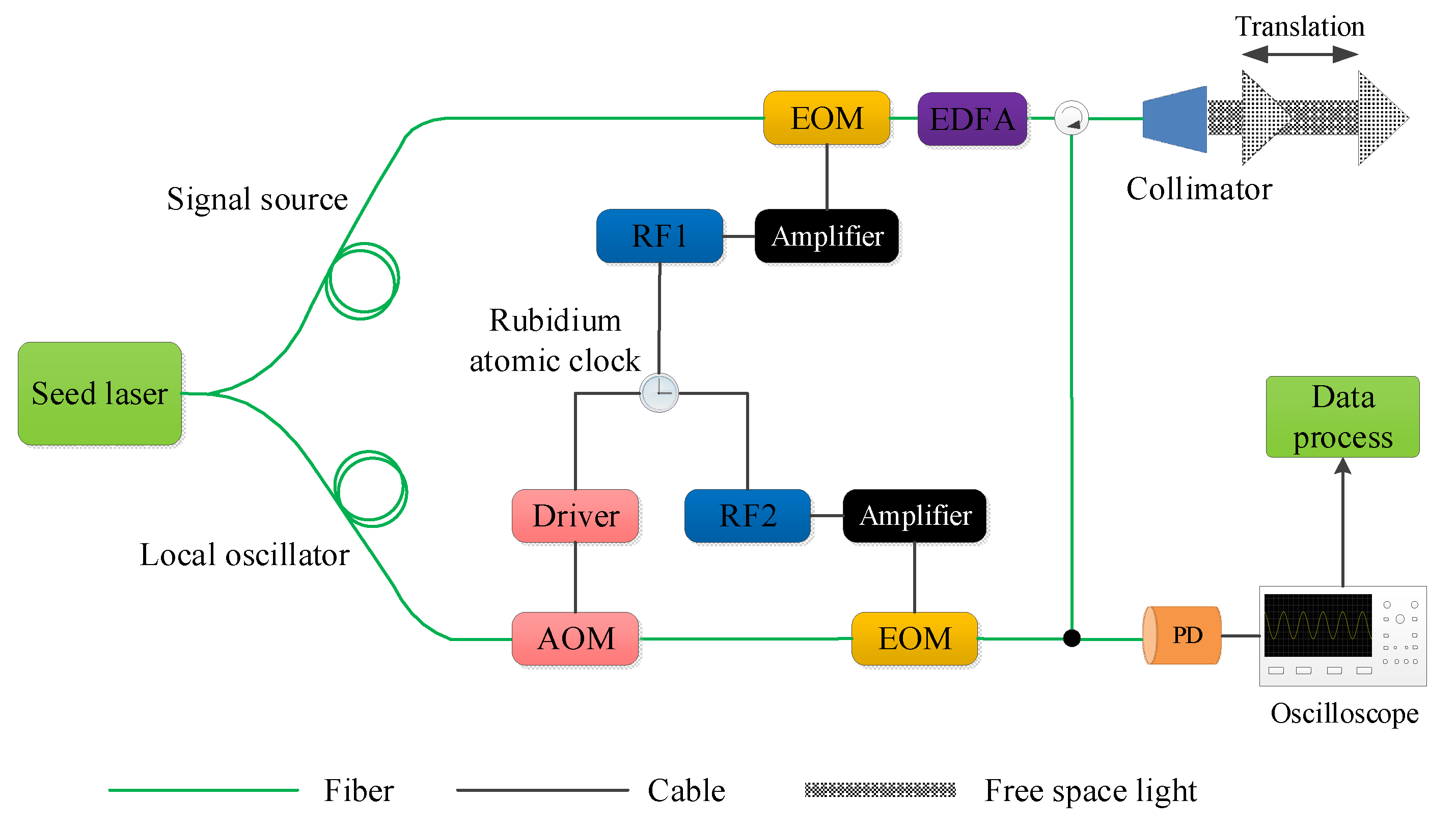
Figure 1 shows the experimental system. The output of the seed laser (RIO ORION Laser Module, 1543.5 nm, 5.1 kHz line width, 18 mW) is spilt into two parts. One part is modulated by an electro-optic phase modulator (EOM, EOSpace, <5 V half-wave voltage V
π, 2 W RF power) with 10 GHz repetition frequency, which works as the seed of the signal source. The output of the EOM is amplified to 500 mW by an Er-doped fiber amplifier. After the optical circular, the beam size of the signal source is expanded to 20 mm by a large collimator (micro laser system, FC40), which can guarantee that the received reflected light is strong enough. Then, the laser is incident on a moving corner prism, which is mounted on an electrical rail (Zolix, LMA-TR-200, travel 200 mm, resolution 1 μm/s) whose velocity can be precisely controlled. The other part serves as the seed of the local oscillator. An acousto-optic modulator (AOM; AA opto-electronic MT110, 110 MHz frequency shift) is used to avoid the frequency ambiguity. Then, the output of the AOM is modulated by another EOM (EOSpace, <5 V V
π, 2W RF power) with 10.001 GHz repetition frequency. The RF driver1 (Agilent N5173B) and RF driver2 (Agilent E8267D) are locked to a rubidium atomic clock (Microsemi 8040, 2×10
−11 stability with 1 s averaging time). Finally, the two parts are combined by a beam splitter and detected by a fast photodetector (Menlosystems FD310). The stored waveforms by an oscilloscope (LeCroy Waverunner 610Zi) can be processed to obtain the Doppler shift information.
4. Results and Discussion
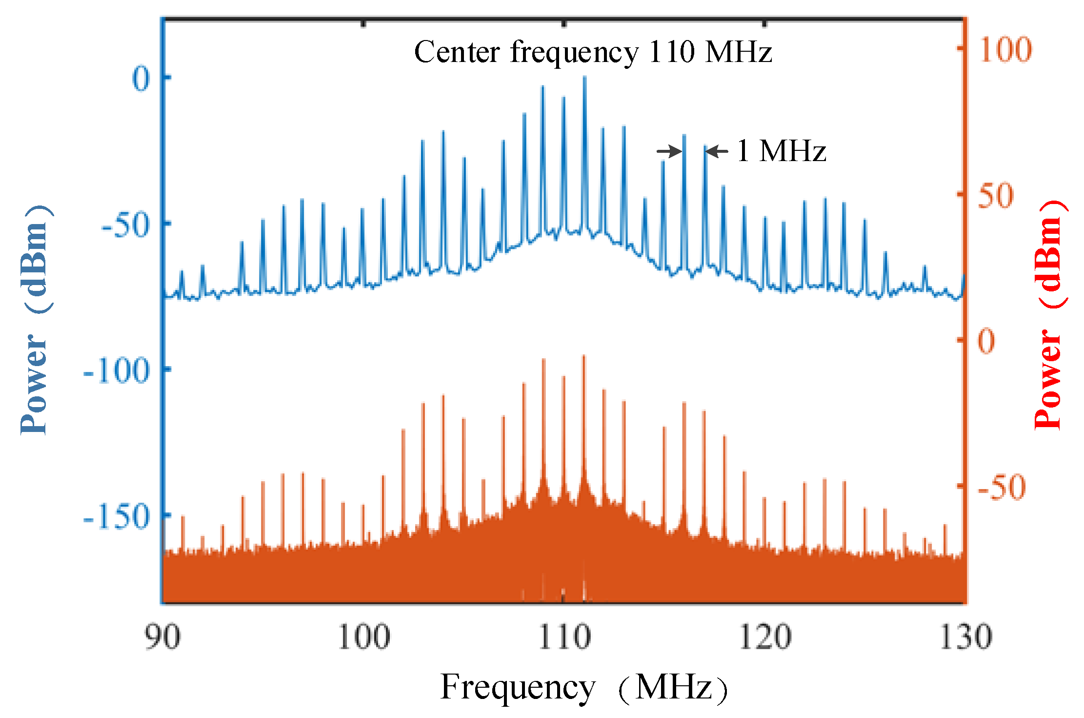
Before moving the target, beat notes between the signal source and the local oscillator were measured by a spectrum analyzer (ROHDE&SCHWARZ FSH8, 3 kHz RBW). Then, the waveform obtained by the oscilloscope was Fourier transformed to obtain the new comb due to beat. As shown in
Figure 2, we can see that the Fourier transform can basically reproduce the beat frequency spectrum. Additionally, the center frequency of the beat notes is 110 MHz, which is the driving frequency of the AOM. The frequency interval of the comb teeth is 1 MHz, which is the frequency difference between the driving frequencies of the two RF drivers. Actually, the frequency of RF driver1 is 10 GHz and the frequency of RF driver2 is 10.001 GHz. This means that
frep.sig = 10 GHz and
frep.loc = 10.001 GHz.
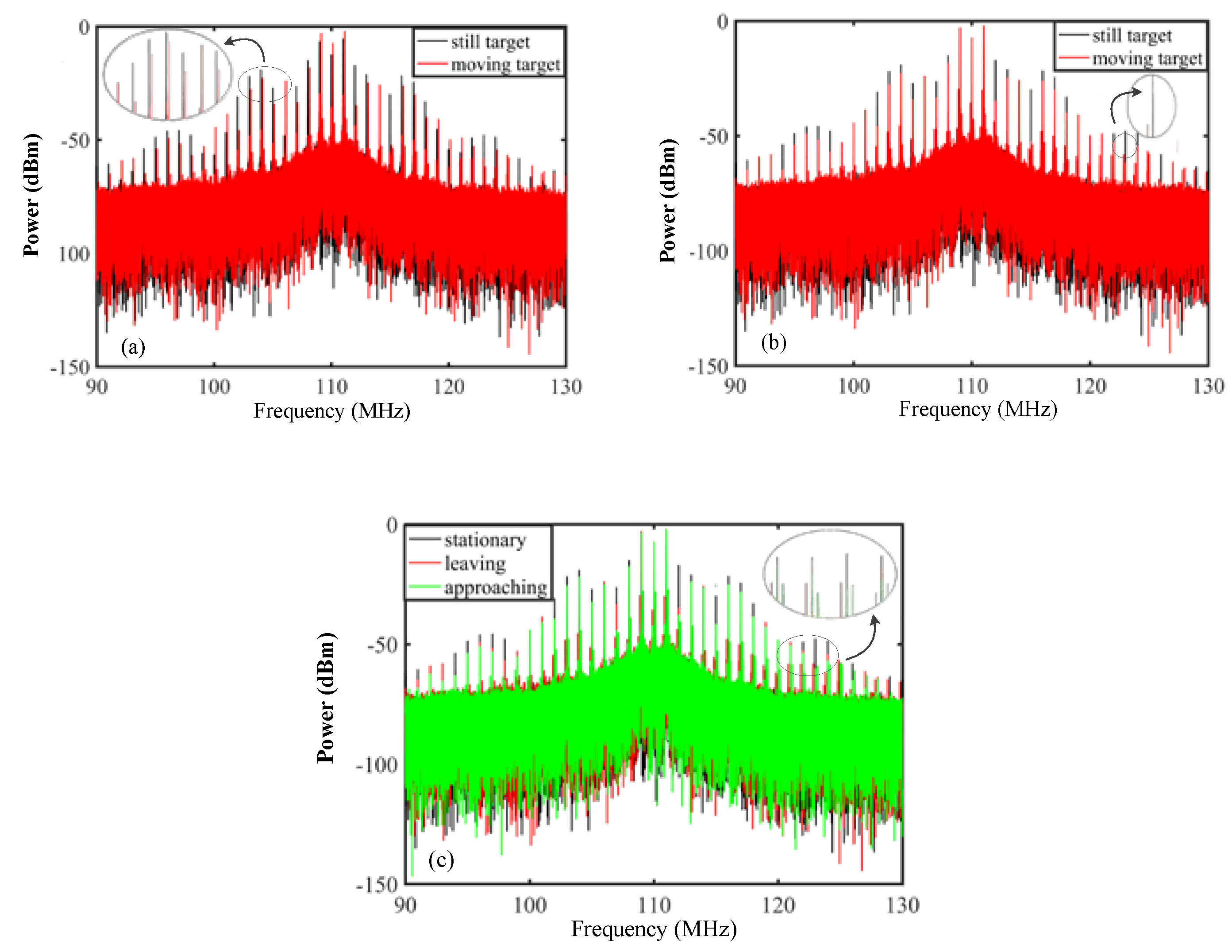
To show the feasibility of the electro-optic dual-comb Doppler velocimeter,
Figure 3 shows the difference between Fourier transforming the waveforms when the target is stationary and when it is moving. In
Figure 3a, the black comb expresses the measured spectrum when the target is stationary and the red comb is that when the target is moving away from the collimator. It can be seen that every comb has a reduced offset due to the Doppler effect. As the target’s velocity is much lower than that of light, the Doppler shift generated at 10 GHz repetition frequency is too small to be seen in the spectrum. In order to show that the repetition frequency has changed, we translate the red comb and move its center frequency to 110 MHz in
Figure 3b. Hence, the changes of frequency interval can be seen on the high-order comb teeth due to the cumulative effect. It is thus proved that the Doppler effect causes a change in the repetition frequency, which can be used to calculate the velocity of a moving target. To show the directional discriminability,
Figure 3c shows the frequency spectrum when the target is stationary, as well as leaving from and approaching the collimator with
v = −100 mm/s and
v = +100 mm/s. As can be seen, for the same teeth of the combs, the green line is on the left and red line is on the right. This proves that approaching leads to an increase in the repetition frequency and leaving leads to a reduction in the repetition frequency.
When processing the data, we selected the two teeth at 110 MHz and 126 MHz to calculate the change in repetition frequency. This means taking the average of 16 repetition frequency data and increasing the resolution by 16 times. The greater the distance between the two teeth involved in the calculation, the higher the resolution. However, we saw only 16 sidebands in the spectrum analyzer; the other sidebands were suppressed due to their weak intensity. Hence, we selected those two teeth to make the calculation. We have conducted experiments to set the moving target at
v from 100 to 300 mm/s with an interval of 50 mm/s and in the directions toward and away from the collimator.
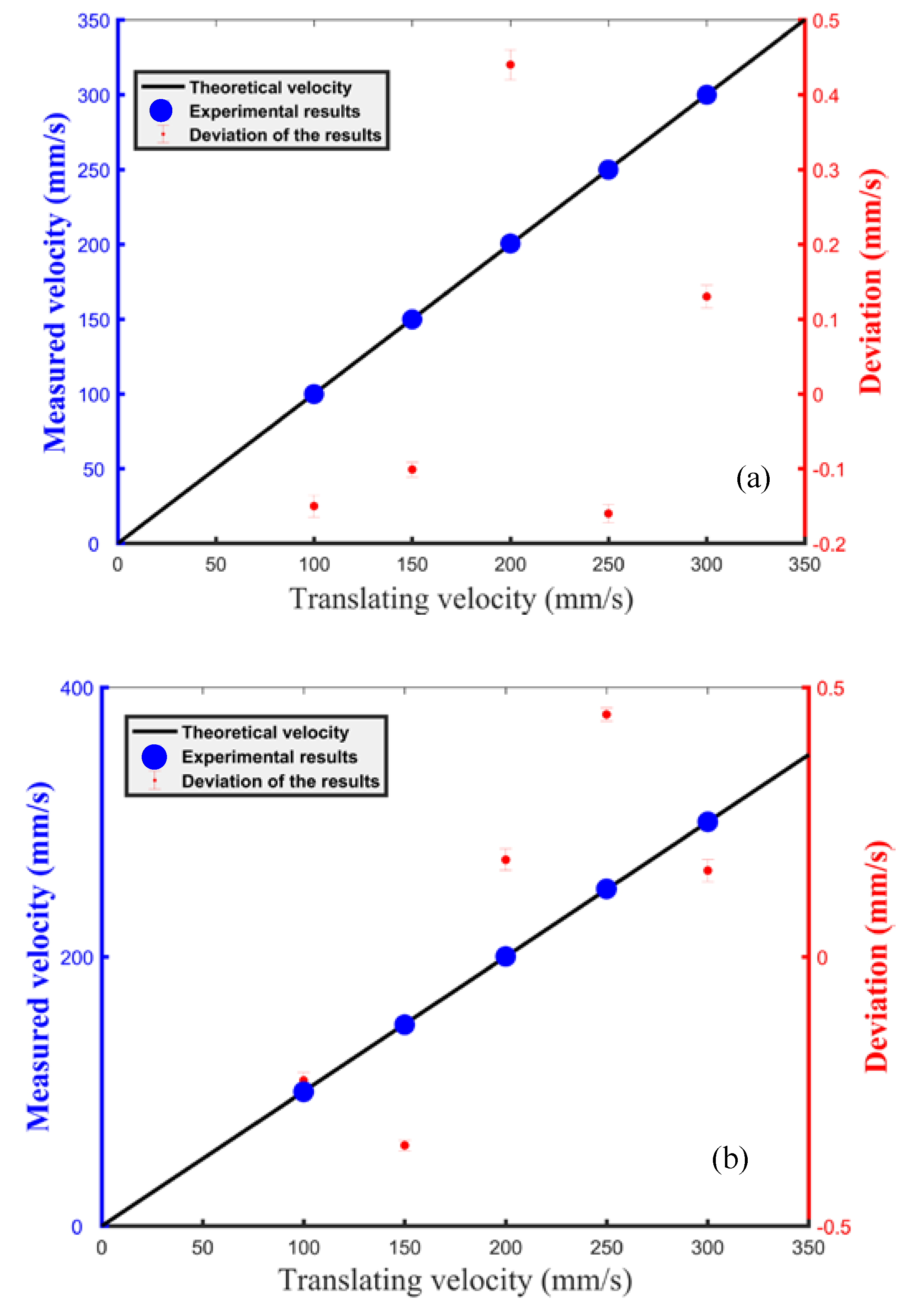
Figure 4 shows the results of velocity measurement. As shown in
Figure 4, the velocity of the target is accurately measured by the dual optical comb LDV with a maximum deviation of 0.44 mm/s. Due to the minimum speed of the electric rail being 100 mm/s, we were not able to measure at a lower speed. In addition, due to the limit of the length of the electric rail, the sampling time was too short at a higher speed to collect enough data.
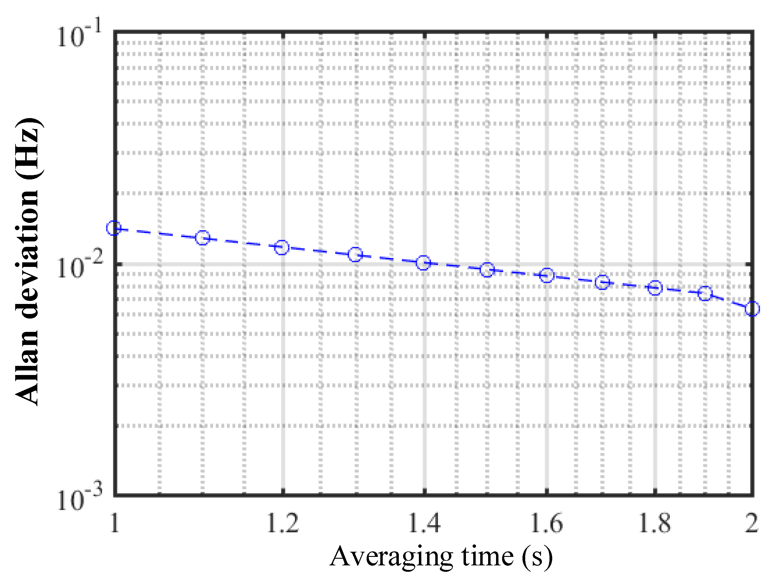
Theoretically, the upper limit of the speed measurement is limited by the difference between the two optical comb repetition frequencies. In this experiment, a difference of 1 MHz limited the maximum speed of the measurement at 15 km/s. Additionally, the resolution was limited by the frequency stability and FFT resolution.
Figure 5 shows the Allan deviation of a 1 MHz frequency, which is mixed with the output of the two RF drivers at 110 MHz and 111 MHz. The Allan deviation is well below 14 mHz, with the averaging time larger than 1 s, which corresponds to a resolution of 0.21 mm/s. In our data processing, the FFT resolution was 5 Hz, which corresponds to a resolution of 75 mm/s. Since we selected 16 teeth to calculate the change of repetition frequency, the resolution could be improved to 4.69 mm/s.
5. Conclusions
In order to achieve a wide range and high accuracy in the field of velocity measurement, an electro-optic dual-comb Doppler velocimeter was proposed and studied in this work. In principle, the proposed velocimeter which was derived is feasible and can further improve velocity measurement accuracy. Experimentally, we locked the repetition frequencies of the two optical combs in the microwave frequency domain and beat them to make the detection. In this way, we verified its high accuracy in the range of 100–300 mm/s. The measured range of 4.69 mm/s to 15 km/s was theoretically derived. The proposed velocimeter combines the merits of high precision, high accuracy, and wide range. In addition, since the repetition frequency used for the measurement is traceable to a rubidium clock, its potentially superior traceability can be utilized in velocity metrology. It is of great meaning and necessity because it helps to provide an available velocimeter with high stability and an extremely compact configuration, making a potential contribution to the velocimeter in practical engineering applications.


