1. Introduction
Helical piles have been used as the foundations of offshore structures over 100 years [
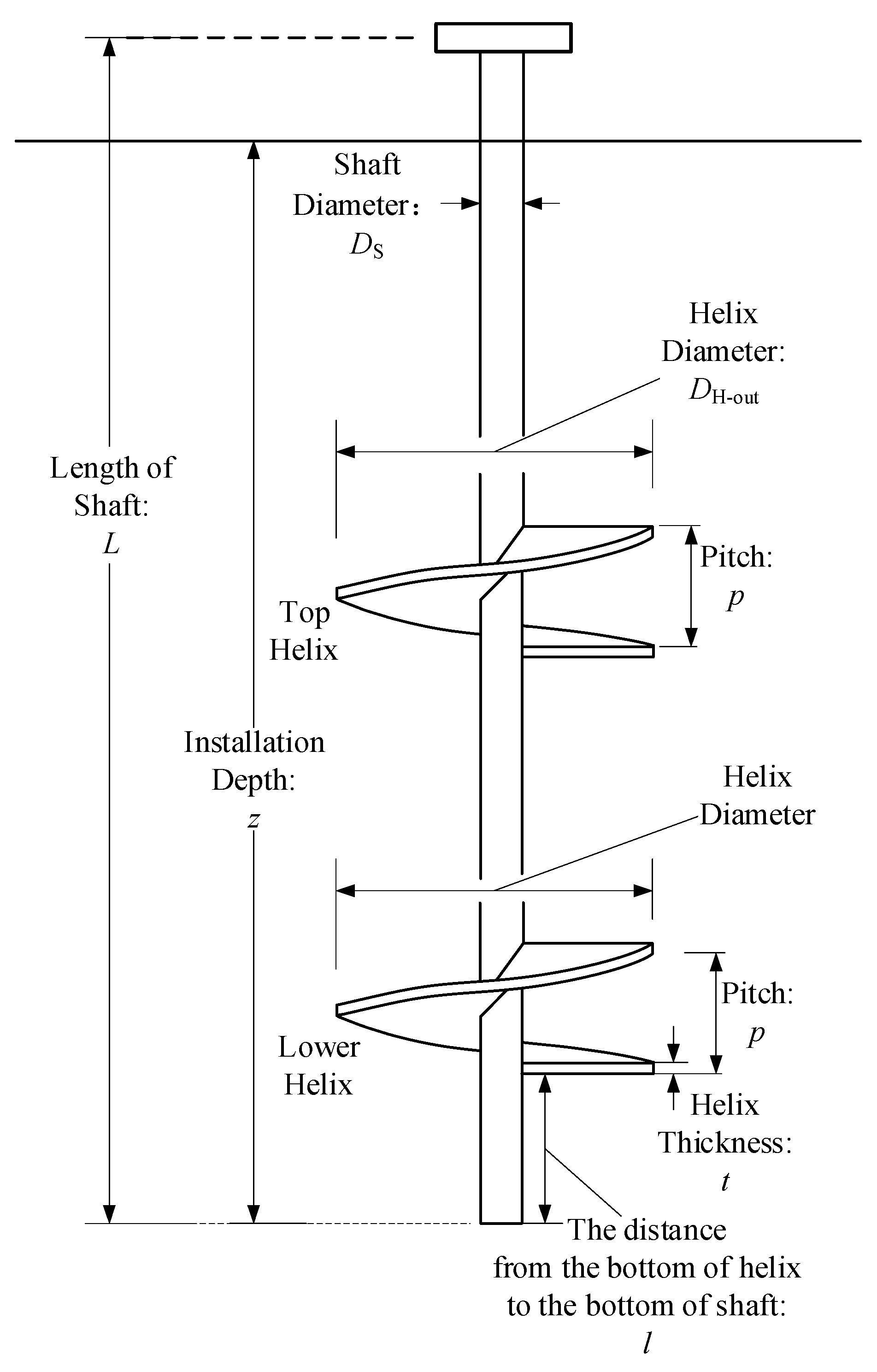
1] to resist tension and compression. The typical helical pile consists of a central shaft and a serious of steel helixes welded on it, as shown in
Figure 1. Helical piles have been employed extensively to support both tensile and compressive forces in telecommunication towers, energy transmission, distribution lines, solar panels, and onshore wind turbine foundations.
Helical piles can be installed with torque and minor compression, quickly and conveniently. Due to the advantages of helical piles, such as: the fast installation process, high uplift capacity and the convenience for recycling, it is being treated as a kind of novel foundation for offshore wind turbines by some scholars [
2,
3]. If helical piles were used as the foundation of an offshore wind turbine, there are three important parts for geotechnical design: (i) the installation process of helical piles; (ii) the loading procedure of helical piles after the installation process; (iii) the recycling process when the loading procedure of helical pile is finished.
For the installation process of helical piles in sand, some scholars have done some research through model tests [
4,
5,
6,
7,
8] and centrifuge tests [
9,
10]. Based on the test results, there are several findings and contributions: (1) the installation process of a helical pile would cause some disturbance to the surrounding soil and the soil traversed by the helix is displaced laterally, which causes the lateral soil pressure to increase during the installation process of a helical pile; (2) based on the tests result and inspired by the lead screw driver theory, some semi-empirical solutions were proposed to predict the installation torque of helical piles in sand; (3) there is a linear relationship between the uplifting capacity of a helical pile,
Qu, and the corresponding torque,
T, required for installing helical piles to the desired depth; the ratio between
Qu and
T is the so-called torque correlation factor (
KT). The value of
KT is influenced by the sand’s relative density and the shape of the helical piles.
For the loading procedure of helical piles after installation process, the main research objective is the uplift capacity of helical piles in sand. Many scholars treated single-plate helical piles as circular plate anchors due to the similar behavior under a tension load when the pitch of helix was small compared with the size of its outer diameter, and a number of single gravity experiments were conducted [
11,
12,
13,
14,
15,
16,
17,
18,
19,
20] to invest the uplift capacity of circular plate anchors and helical piles in sand. Besides, Hao et al. [
21] conducted a series of uplift tests in dense silica sand through geo-centrifuge to analyze the influence of the relative embedment depth of the helix, number of helices and the spacing of adjacent helixes on the uplifting capacity of helical piles in dense sand. Merifield et al. [
22,
23] analyzed the uplift-capacity of circular plate anchor through FEM.
After finishing their service, helical piles could be recycled from sand easily with reverse torque, just like the removal process of a screw nail because of their particular shape. The recycling process of helical pile is the key point for the reuse of a helical pile and the cost reduction; however, studies on the recycling process of helical pile is still rare and there is no basis to confirm the equipment for the recycling process. Therefore, some relevant study about the topic is very necessary.
The objectives of the present paper are (i) a more fundamental understanding of the recycling process of single-plate helical piles in dense sand, and proposing a theoretical model to predict the recycling torque of single-plate helical pile in dense sand; and (ii) conducting a series of model tests to analyze the recycling process of single-plate helical piles in dense sand, and verifying the accuracy and practicability of this theoretical model by the comparison between the theoretical results and the test results.
2. Theoretical Model
In this paper, the research focuses on the recycling process of single-plate a helical pile in dense sand. It is necessary to establish a systematic analysis about the force conditions of single-plate helical pile during the recycling process for formulating a theoretical model to predict the recycling torque of single-plate helical pile in dense sand. Inspired by the assumption proposed by Ghaly [
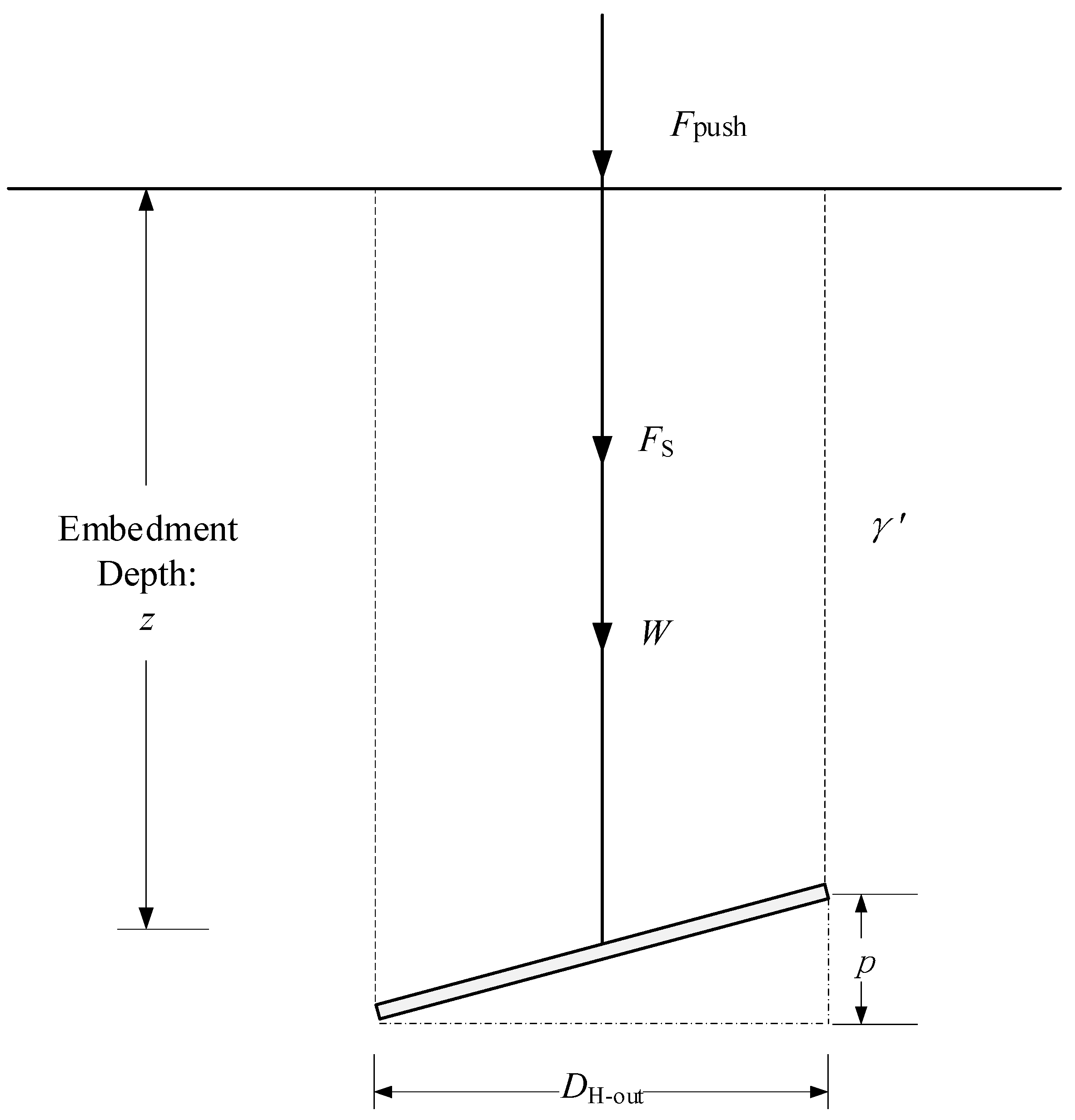
7] for predicting the installation torque of a single-plate helical pile in sand, the helical pile is assumed fixed at a given depth and prevented upwards movement from the sand. While the application of the recycling torque is continued, the helix should bear the weight of the sand within the cylinder area which is on top of the helix, as shown in
Figure 2. The torque applied from outside is resisted by a system of forces acting on the upper surface of the helix. As shown in
Figure 3, the vertical force (
V) that caused by the recycling process of helical pile is equal to the sum of the weight of the sand in the cylinder area above the helix (
W), the frictional resistance on the central shaft (
FS), and the force acting on the central shaft from outside (
Fpush):
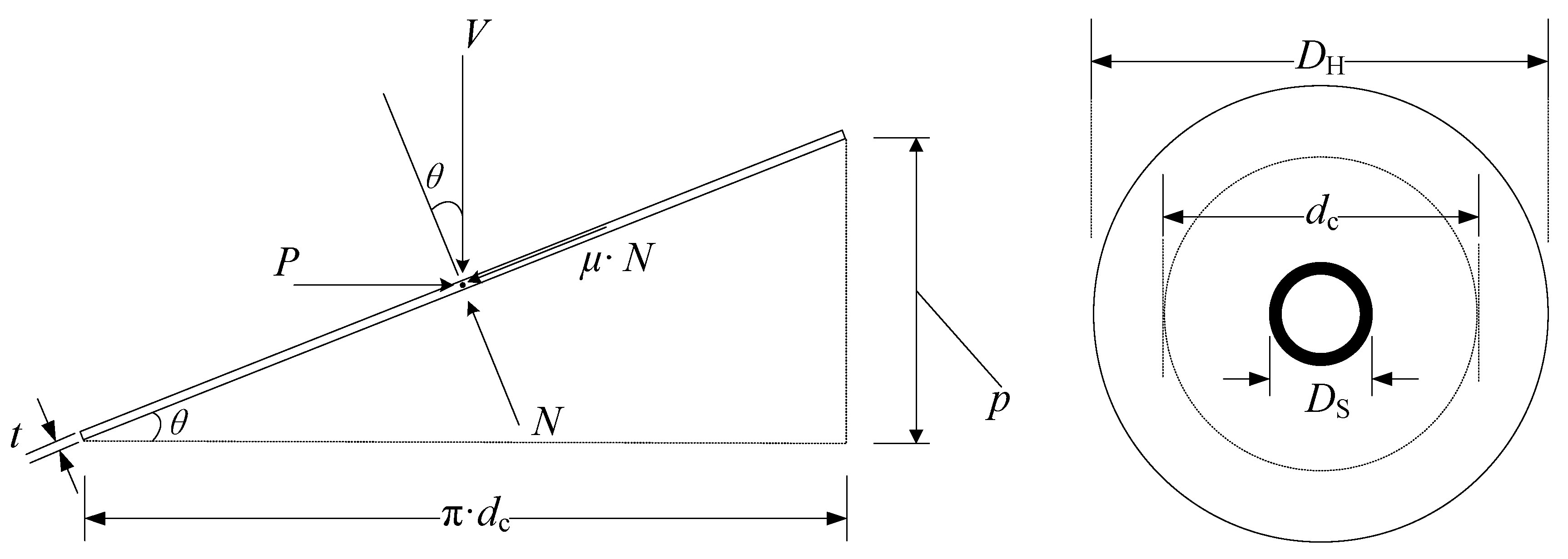
Figure 3 shows a developed helix and the forces affecting the applied torque. The forces that develop due to anchor’s rotation without upwards movement are, vertical force (
V), frictional force (
μ N), a force (
R) parallel to the base of the triangle to overcome the frictional force (
μ N), and a force (
N) normal to the inclined plane of the helix to satisfy the condition of the static equilibrium of the system. It should be mentioned that the forces mentioned above are distributed pressures on the helix; however, to simplify the theoretical analysis, these forces are considered concentrated forces acting on a point. According to the force conditions shown in
Figure 3, the corresponding equations could be shown as:
where
Based on Equations (2) and (3),
R could be calculated as below:
Considering the influence of the shape of helix, the weight of sand in the cylinder area above the helix could be expressed as:
where
DH = outer diameter of helix.
DS = outer diameter of the central shaft.
γ’ = effective unit weight of the sand.
p = pitch of helix.
z = embedment depth.
l = the distance from the bottom of helix to the bottom of shaft.
dc = the represented diameter where concentrated forces acting on.
The torque acting on the helix (
TH) can be calculated as follows:
dc could be expressed as:
Based on the equations mentioned above, the torque acting on the helix (
TH) can be expressed below:
The torque acting on the central shaft is expressed below:
where,
k is the coefficient of earth pressure, which should be confirmed according to the stress state of soil. Therefore, the total recycling torque could be calculated as below:
In order to verify the accuracy and credibility of the theoretical model mentioned above, a series of tests about the recycling process of single-plate helical piles were conducted in sand.
3. Test Process
3.1. Model Piles, Test Apparatus, and Test Site
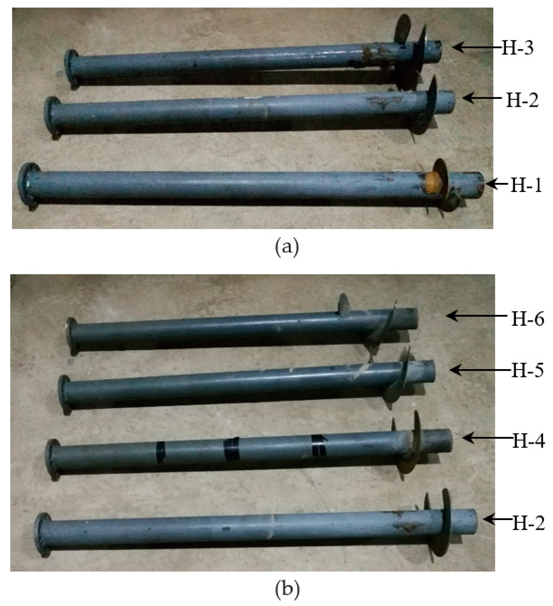
There were six single-plate helical piles (see
Figure 4) used in model test. In order to connect these model piles with relevant test apparatus used in the model test, there was a flange on the top of each helical pile. All the helical piles were manufactured by steel with one steel helix with thickness,
t = 0.003 m, welded on a steel central shaft, which was steel pipe pile with the outside diameter of shaft,
DS-out = 0.06 m, the inside diameter of shaft,
DS-in = 0.052 m, and the length of shaft,
L = 1 m. The outer diameters,
DH-out = 0.12 m, 0.16 m, and 0.20 m, and pitches of helixes,
p = 0.03 m, 0.06 m, 0.10 m, and 0.16 m, used in each model pile were different. The details about the dimensions of model piles are shown in
Table 1.
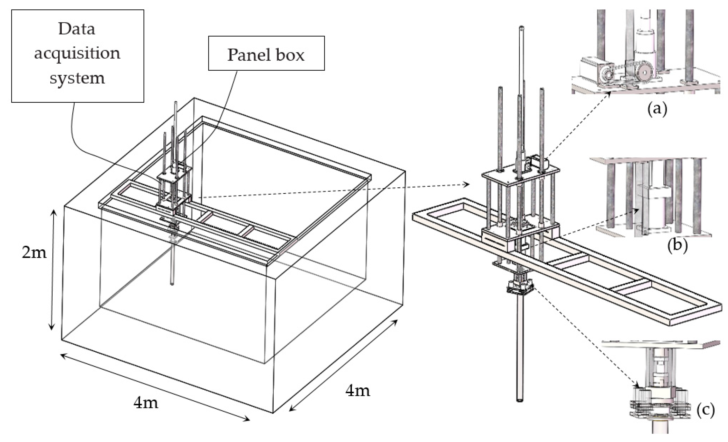
All tests were conducted in a reinforced concrete tank with dimensions of 4 m internal length, 4 m internal width, and 2 m internal depth (see
Figure 5) in Tianjin University. The test apparatus, which was fixed with a hold and placed on the tank, consisted of three parts: (a) The servo motor which controlled the vertical motion of model piles; (b) a servo motor which controlled the rotational motion of model piles; (c). the monitoring part which consisted of one tension and compression load cell (measuring range: −2–2 t; accuracy: 10 N) and a torque sensor (measuring range: −500~500 N·m; accuracy: 0.25 N·m). For the tension and compression load cell, its bottom was connected with a steel plate, and the model pile was connected with this plate through its flange. In order to avoid the influence of torque on the tension and compression load cell, there were four linear bearings fixed on the steel plate. For the torque sensor, there were four fixed bars around it to prevent the influence of compression or tension. With the help of device mentioned above, two sensors could work independently and monitor the vertical force and installation torque of helical pile at the same time. The test apparatus could control the vertical motion and the rotational motion of helical piles at the same time. In order to provide enough counter-force (2.5 t), two concrete blocks, each with 500 kg weight, were put on the both ends of the hold. The test apparatus had contacts with the panel box and the data acquisition system.
3.2. Sample Preparation
The sand used in tests was fine silica sand collected from a site off the east coast of Tianjin with poor grain gradation. The properties of sand are listed in
Table 2. The dry sand was placed into the tank by pluviation to keep its relative density at
ID = 88%; the model pile was pre-embedded with the same target embedment depth,
z = 0.6 m; the total thickness of the sand from the bottom of the tank to the soil surface was equal to 1.4 m. Then, the sand sample was saturated by elevating water with a velocity of 0.25 m/day, which is slow enough to avoid uneven seepage or piping. The final thickness of the sand sample, overlaid by 0.1 m water to keep saturated, was 1.5 m. After the preparation of sand sample, the DPL tests were conducted to make sure of the uniformity of the sand sample; it is DPL tests (light dynamic penetration tests), which can provide reliable data for soil depth less than 8 m [
24]. They were conducted to make sure of the uniformity of the sand sample. The introduction of the DPL test can be found in a European Standard [
25]. The results of the DPL test were used to double check the consistency and repeatability of soil.
3.3. Direct Shear Interface Tests
During the recycling process of single-plate helical pile, the pile–soil interface friction angle is a vital factor. The pile–soil interface friction angle is investigated extensively, so that a soil–pile interface friction angle can be determined [
26,
27,
28,
29]. This angle is influenced not only by internal friction angle of soil, but also governed by the steel roughness, the average grain size,
D50, and the sand type. Reddy et al. [
30] presented a simple means of measuring the interface friction angle between a soil and a pile surface using conventional, direct shear test apparatus with a few modifications, and concluded that the interface friction angle cannot be expressed as a constant percentage of the internal friction angle of the soil, and that the interface friction angle is a function of interface properties. In order to measure the pile–soil interface friction angle for this study, a similar test of that in Reddy’s paper was done in this study: the plate, which used the same material and same thickness as the helix, was dragged laterally at a constant velocity of 0.1 mm/min. The relative density of sand,
ID, used in this is equal to 88%, and the residual interface friction angle was
= 15°.
3.4. Testing Procedure and Program
After finishing the preparation of sand sample, the model pile and the test apparatus was connected through the flange on top of model pile and the flange at the bottom of the test apparatus; then, the single-plate helical piles with different outer diameters and pitches of helixes were recycled under different stable recycling speeds:
vR = 1
p/r, 0.8
p/r, and 0.5
p/r. During the recycling process, the recycling torque,
TR, and the vertical force on central shaft,
Fpush, were monitored. The testing program (see
Table 3) was designed for the following objectives:
Investigate the influence of recycling speeds, vR = 0.5 p/r, 0.8 p/r, and 1 p/r, on recycling torque, TR, and the vertical force on central shaft, Fpush, during the recycling process.
Investigate the influence of outer diameters of helixes, DH-out = 012 m, 0.16 m, and 0.20 m, on recycling torque, TR, and vertical force on the central shaft, Fpush, during the recycling process.
Investigate the influence of pitches of helixes, p = 0.03 m, 0.06 m, 0.10 m, and 0.16 m, on recycling torque, TR, and vertical force on central shaft, Fpush, during the recycling process.
Based on the test results, to understand the recycling process of single-plate helical piles deep in sand and analyze the influence of vertical force on central shaft, Fpush, and recycling torque, TR.
To verify the accuracy of theoretical model on the basis of the test results.
4. Test Results and Discussion
The test results consist of three parts: (i) the test results about the recycling process of single-plate helical pile in dense sand under different outer diameters of helix, DH-out = 0.12 m, 0.16 m, and 0.20 m; (ii) the test results about the recycling process of a single-plate helical pile in dense sand under different recycling speeds, vR = 1 p/r, 0.8 p/r, and 0.5 p/r; and (iii) the test results about the recycling process of a single-plate helical pile in dense sand under different pitches of helix, p = 0.03 m, 0.06 m, 0.10 m, and 0.16 m. The details about the test results are shown below.
4.1. The Test Results for Part One
The research emphasis of this part is about the influence of outer diameters of helix on recycling torque of single-plate helical pile. The test results about the recycling torque (
TR) of a single-plate helical pile; the embedment depth (
z) responses of single-plate helical piles; the vertical force on the central shaft (
Fpush) of a single-plate helical pile; and the embedment depth (
z) responses of single-plate helical piles with same size of the pitch of helix,
p = 0.03 m, different outer diameters of helixes,
DH-out = 0.12 m, 0.16 m, and 0.20 m, and same recycling speed,
vR = 1
p/r, are compared in
Figure 6,
Figure 7 and
Figure 8. According to the results of
Figure 6,
Figure 7 and
Figure 8, we made the following observations:
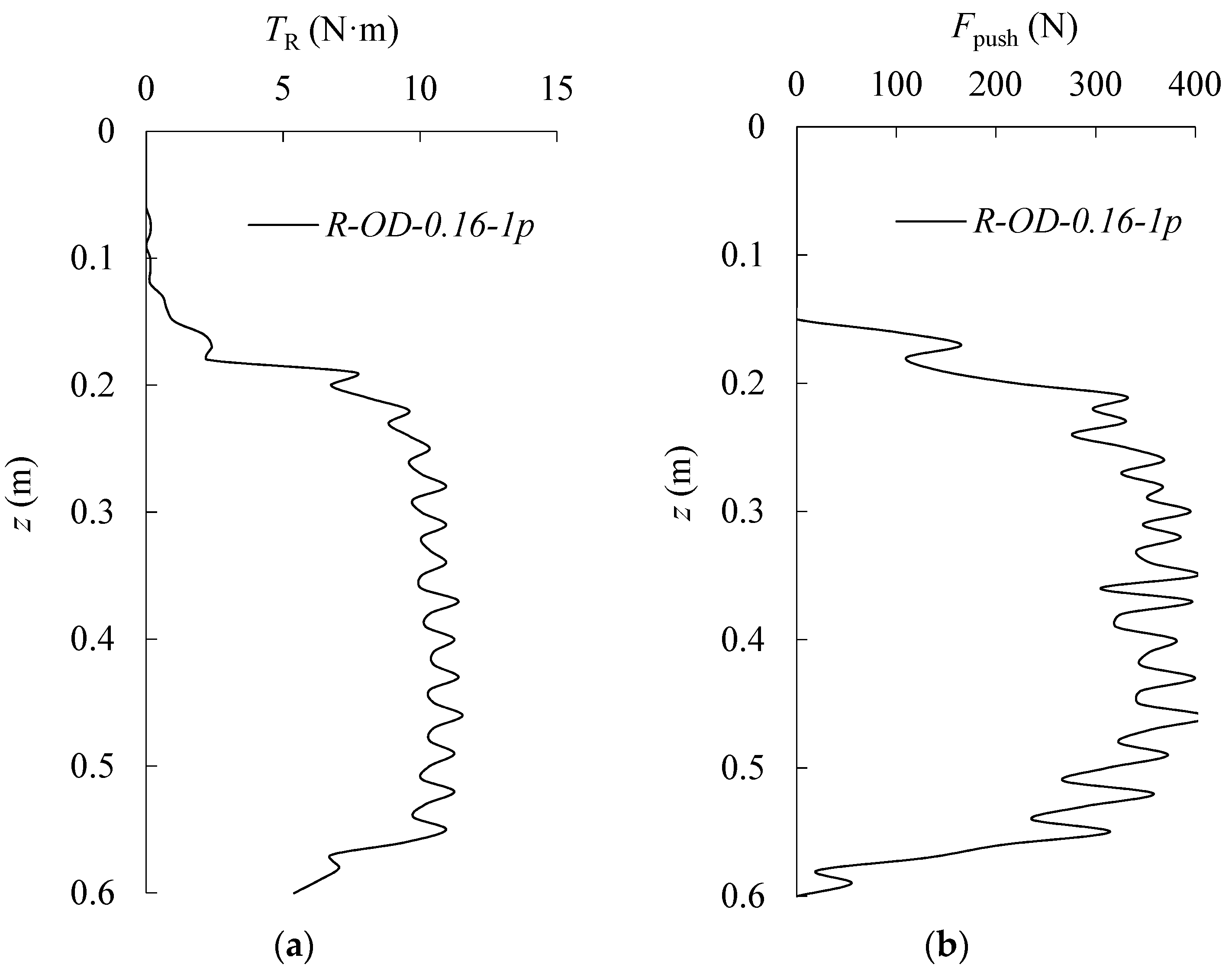
The changing trends of the recycling torque, TR, of the single-plate helical piles in dense sand with different outer diameters of the helix are the same and all consist of three parts: For the first part, the recycling torque, TR, increases sharply from the beginning of recycling process until the recycling torque reaches a peak value. For the second part, the recycling torque decreases with a relatively slow speed after the peak value. After the process of the second part, the recycling torque decreases sharply when the helix is close to the ground’s surface.
Besides, the recycling torque, TR, of the single-plate helical piles increases with the rise of the size of the out diameter of helix, DH-out.
For the vertical force on central shaft, Fpush, of the single-plate helical piles, it also has that similarly changing trend of the recycling torque, TR—that of the single-plate helical piles. It increases sharply from the beginning of the recycling process, and after that it drops stably from the peak value until the helix is close to the soil’s surface. Similarly, the vertical force on central shaft, Fpush, of the single-plate helical piles, also increases with the raise of the size of the out diameter of helix, DH-out.
According to the change trends of the vertical force on central shaft, Fpush, and the recycling torque, TR, of the single-plate helical piles, their vibration changes are synchronous, which means Fpush also has an effect on TR.
4.2. The Test Results for Part Two
The research emphasis of this part is about the influence of the recycling speed,
vR, on the recycling process of a single-plate helical pile. For the influence of the recycling speed,
vR, on the recycling process, the test results of the recycling torque (
TR); the embedment depth (
z) responses of the single-plate helical pile; the vertical force on central shaft (
Fpush) of the single-plate helical pile; and the embedment depth (
z) responses of single-plate helical pile with same pitch of helix,
p = 0.03 m, same outer diameters of helix,
DH-out = 0.20 m, and different recycling speeds,
vR = 0.8
p/r and 1
p/r, are compared in
Figure 8 and
Figure 9. Observations from
Figure 8 and
Figure 9 led to the following comments:
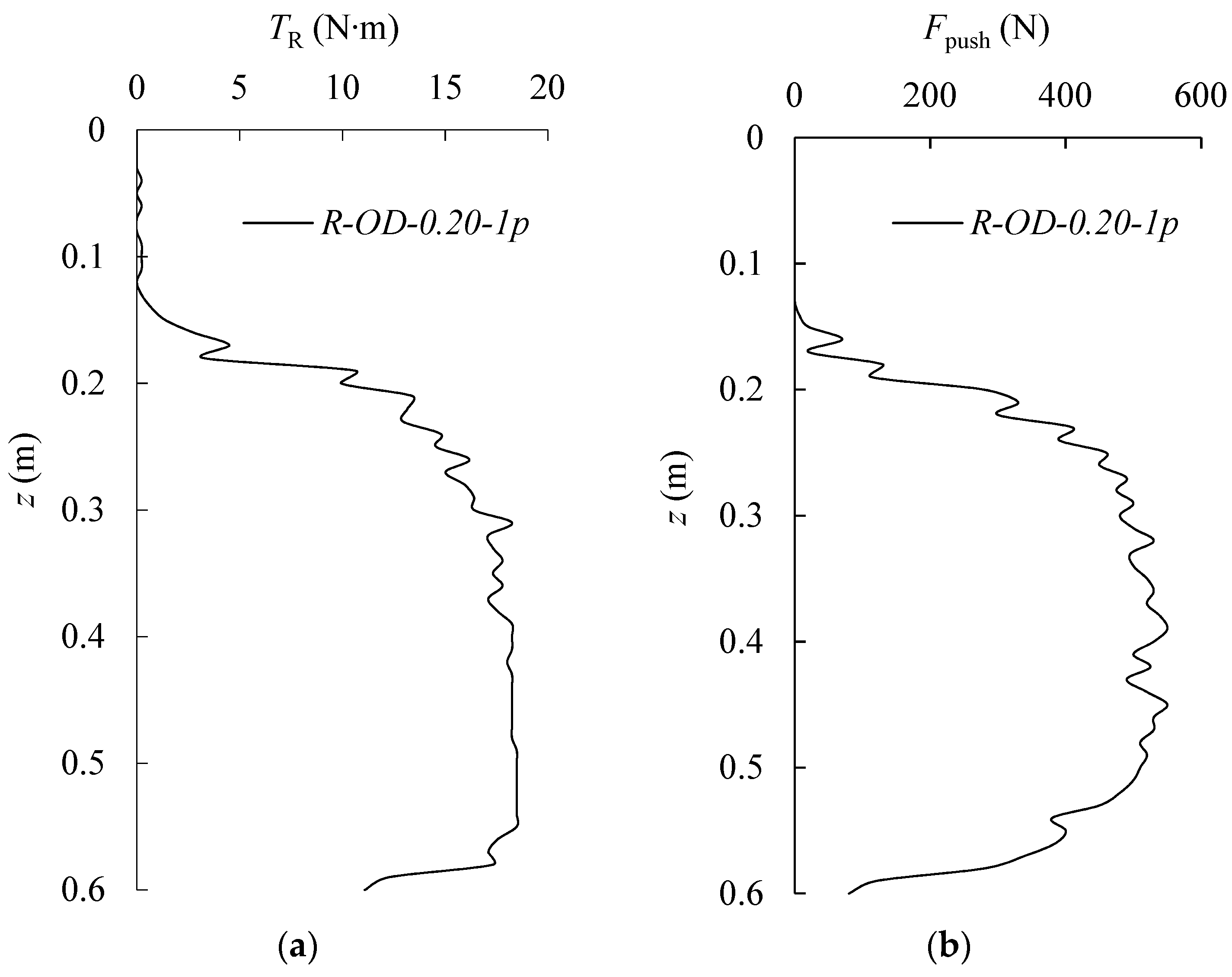
The change-trends of the recycling torque, TR, of the single-plate helical pile and the vertical force on central shaft, Fpush, of the single-plate helical piles during the recycling process are same under different recycling speeds, vR; they both increase significantly at the beginning of the recycling process of the single-plate helical piles until they reach some peak value. Then they drop stably until the helix is close to the soil surface.
Besides the recycling torque, TR, of the single-plate helical pile and the vertical force on central shaft, Fpush, of the single-plate helical pile both increase with the increase of the recycling speed, vR.
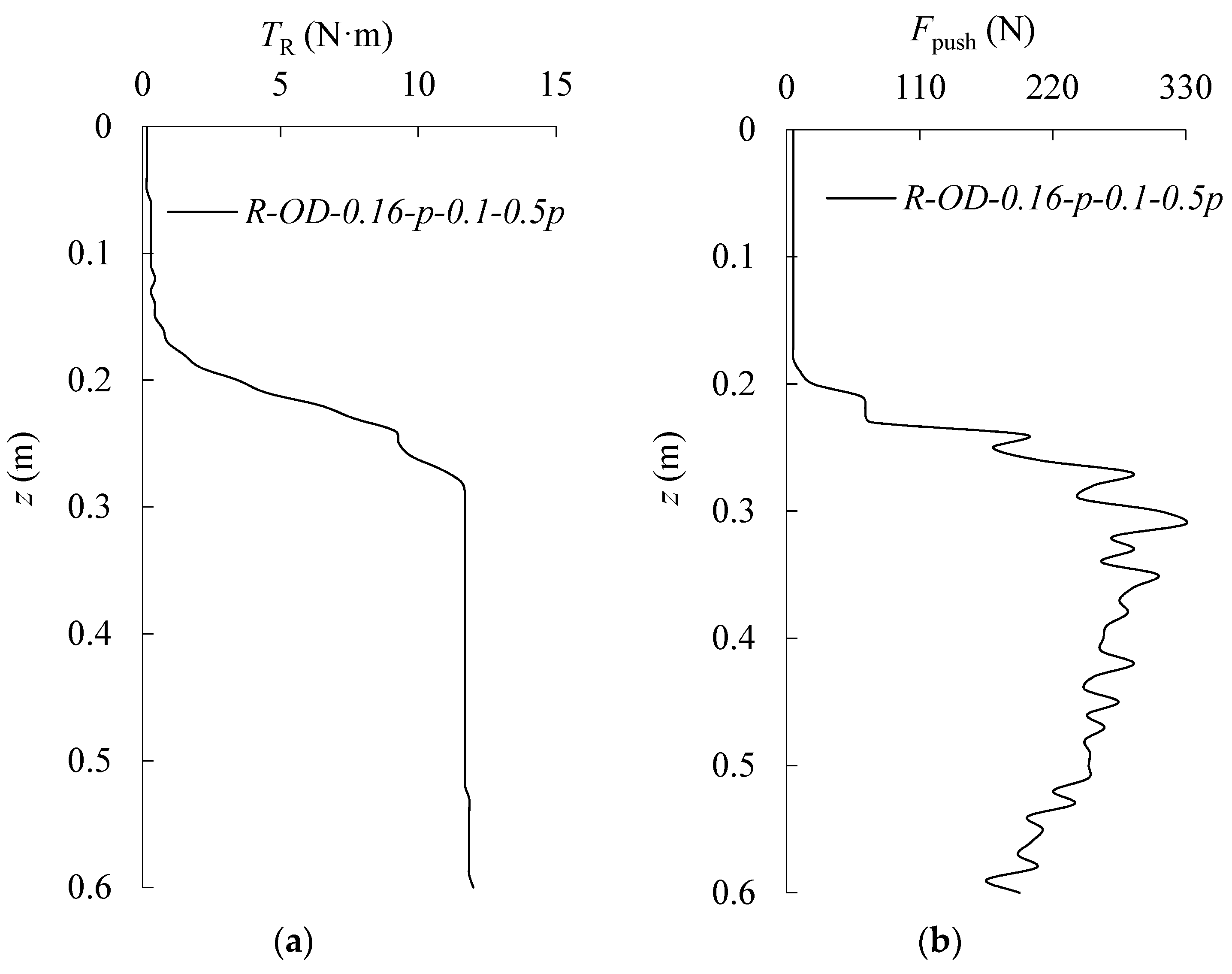
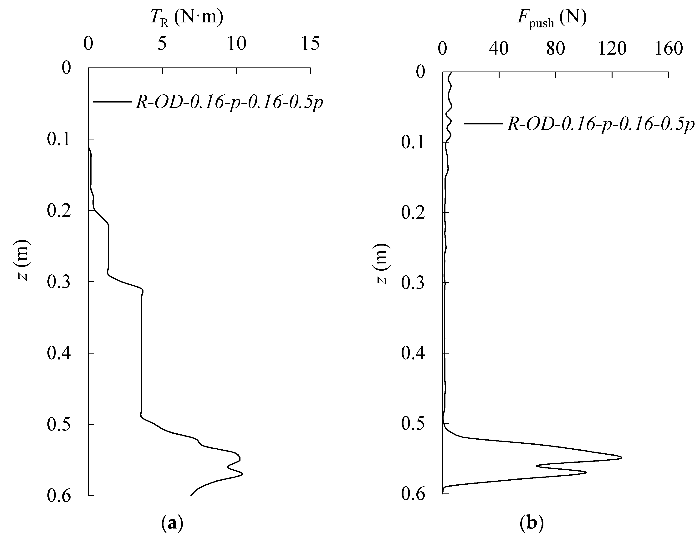
4.3. The Test Results for Part Three
The research emphasis of this part is about the influence of the pitch of helix,
p, on the recycling process of single-plate helical pile. For the influence of the pitch of helix,
p, on the recycling process, the recycling torque (
TR); the embedment depth (
z) responses of the single-plate helical pile; the vertical force on central shaft (
Fpush); the embedment depth (
z) responses of single-plate helical piles with same outer diameters of helix,
DH-out = 0.16 m, same recycling speeds,
vR = 0.5
p/r, and different pitches of helix,
p = 0.03 m, 0.06 m, 0.10 m, and 0.16 m, are compared in
Figure 10,
Figure 11 and
Figure 12. Observations from
Figure 10,
Figure 11 and
Figure 12 lead to the following comments:
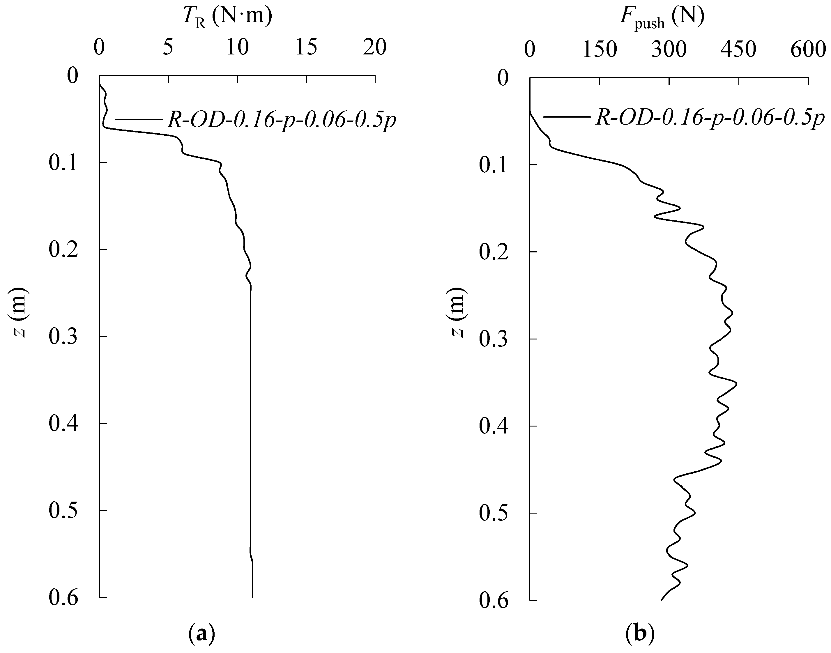
When the pitches of helix are different, the recycling torque, TR, and the vertical force on the central shaft, Fpush, of the single-plate helical pile, both have three stages during the recycling process of the single-plate helical pile: (i) reach the peak value rapidly at the beginning of the recycling process; (ii) keep at a stable value for some distance; (iii) and drop sharply when the helix is close to the soil surface.
The pitch of helix, p, also has significant influence on the recycling torque, TR, and the vertical force on central shaft, Fpush, of the single-plate helical pile: (i) the distance of the stable value for the second part of recycling process decreases with the increase of helix, p; (ii) the depth of the starting point for the third part of recycling process increases with the rise of helix p.
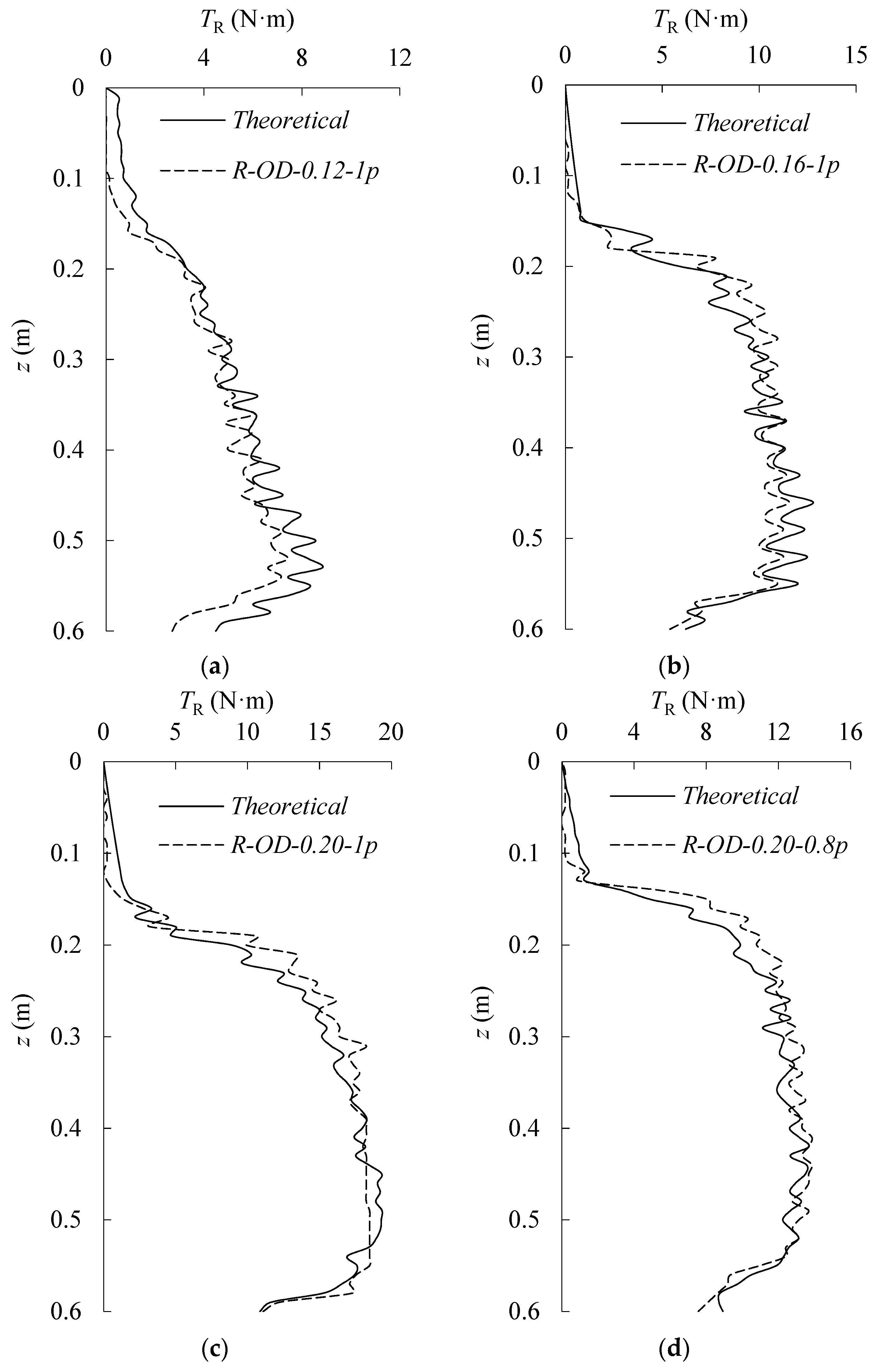
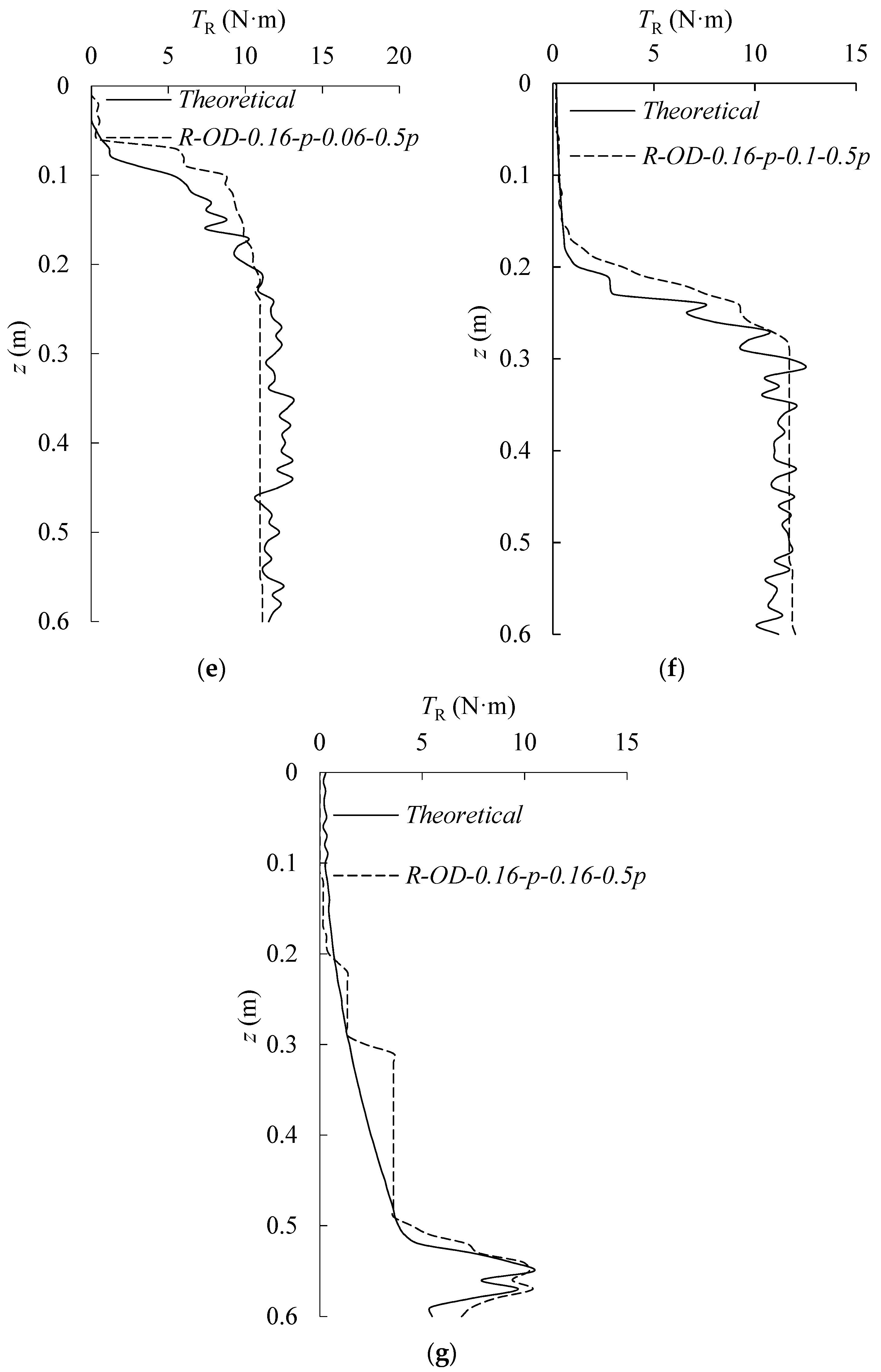
5. Verification
In order to verify the accuracy of the theoretical model mentioned above and know more about the recycling process of the single-plate helical piles in sand, the test results and the corresponding results of theoretical model were compared, as shown below. Considering that the central shaft used in the test above is steel pipe pile, the recycling torque on shaft surface,
TS, could be divided into two parts: the recycling torque on the inside of shaft surface,
TS-in, and the recycling torque on the outside of shaft surface,
TS-out. The corresponding equation could be expressed as below:
Because the model piles were pre-embedded and there is no pushing of the soil during the recycling process of the helical piles along the surface of the central shaft, and just a little part of soil, which is closed to the bottom of pile, is under the condition of unloading, the coefficient of soil pressure at-rest,
k0, is used in Equations (12) and (13). According to the Equations (10)–(13), the recycling torque of the single-plate helical pile with pipe pile shaft in sand can be calculated by equation below:
Based on the Equation (14), the recycling torques,
TR, got from the theoretical model under different conditions, were compared with the results from the model tests, as shown in
Figure 13.
As shown in
Figure 13, the theoretical results of the recycling torque and test results have a good fit with each other from the beginning to the end of the recycling process of a single-plate helical pile, no matter the outer diameters of helix,
DH-out, the recycling speeds,
vR, and the pitches of helix,
p, changed.
6. Discussion and Concluding Remarks
Being inspired by the removal process of a nail from wood or a steel block, we applied the force analysis to a helix in sand; a theoretical model was proposed in this paper to predict the recycling torque of the single-plate helical pile in sand. In order to verify the accuracy and practicability of the theoretical model, a series of tests were conducted to analyze the influence of the outer diameter of the helix, DH-out, the pitch of helix, p, the recycling speed of helical pile, vR, and the vertical force on the central shaft, Fpush, and the recycling torque, TR. According to the test results and the results of theoretical model, some conclusions were accumulated below:
The theoretical results and the test results both show the size of the helix (the outer diameters of helix, DH-out, and the pitches of helix, p) have great influence on the recycling torque of the single-plate helical pile. The recycling torque, TR, of the single-plate helical pile increases with a rise of the outer diameter of the helix, DH-out, when the recycling speeds of helical piles, vR, and the pitch of helix, p, are the same.
For the pitch of helix, p, it changes the weight of the soil which is on the top of the helix and changes the recycling torque indirectly when the embedment of helix is constant.
The recycling speed of helical pile, vR, also has effect on the recycling process of single-plate helical pile. The vertical force on central shaft, Fpush, and the recycling torque, TR, of the single-plate helical pile both increase with the rise of the recycling speed of the helical pile, vR; however, the recycling speed of helical pile, vR, does not influence the recycling torque directly; it has a direct relationship with the vertical force on central shaft, Fpush.
For the vertical force on central shaft, Fpush, has a direct relationship with the recycling torque, TR, of single-plate helical pile. With the rise of the vertical force on central shaft, Fpush, the corresponding recycling torque, TR, increases.
The theoretical results are in great agreement with the corresponding experimental results in different conditions. Based on the verification of a series of tests, the accuracy of the proposed theoretical model, which was used to predict the recycling torque, TR, of single-plate helical piles in sand with different sizes of helix and different vertical forces on the central force, Fpush, was proven.
With this theoretical model, the gap in the research about the recycling torque of a single-plate helical pile is filled and designers can have a helpful reference for predicting the recycling torque of the single-plate helical pile in dense sand, and choose suitable equipment for the recycling of single-plate helical piles in dense sand.
Author Contributions
Conceptualization, H.D. and P.Z.; methodology, H.D., P.Z., and L.W.; test, L.W., Y.L., and P.Z.; validation, Y.T. and P.Z.; formal analysis, L.W. and Y.T.; investigation, L.W., P.Z., and Y.L.; data curation, L.W. and X.Q.; writing—original draft preparation, L.W.; writing—review and editing, L.W., P.Z., and Y.T.; supervision, H.D., P.Z., and Y.T.; project administration, H.D. and P.Z.; funding acquisition, H.D. and P.Z.
Funding
This research was supported by the National Natural Science Foundation of China (number 51779171, number 51679163), the Innovation Method Fund of China (number 2016IM030100), and the Tianjin Municipal Natural Science Foundation (number 17JCYBJC22000).
Conflicts of Interest
The authors declare no conflict of interest.
References
- Alan, L.J. Historical Development of iron screw-pile foundations: 1836–1900. Int. J. Hist. Eng. Technol. 2011, 81, 108–128. [Google Scholar]
- Byrne, B.W.; Houlsby, G.T. Helical piles: An innovative foundation design option for offshore wind turbines. Philos. Trans. R. Soc. A Math. Phys. Eng. Sci. 2015, 373, 20140081. [Google Scholar] [CrossRef] [PubMed]
- Spagnoli, G.; Gavin, K. Helical piles as a novel foundation system for offshore piled facilities. In Proceedings of the Abu Dhabi International Petroleum Exhibition and Conference, Abu Dhabi, UAE, 9–12 November 2015. [Google Scholar] [CrossRef]
- Hoyt, R.M.; Clemence, S.P. Uplift capacity of helical anchors in soil. In Proceedings of the 12th International Conference on Soil Mechanics and Foundation, Rio De Janeiro, Brazil, 13–18 August 1989; Balkema, A.A., Ed.; Balkema: Rotterdam, The Netherlands, 1989; pp. 1019–1022. [Google Scholar]
- Ghaly, A.; Hanna, A.; Hanna, M. Uplift behavior of screw anchors in sand. I: Dry sand. J. Geotech. Eng. 1991, 117, 773–793. [Google Scholar] [CrossRef]
- Ghaly, A.; Hanna, A. Experimental and theoretical studies on installation torque of screw anchors. Can. Geotech. J. 1991, 28, 353–364. [Google Scholar] [CrossRef]
- Ghaly, A.; Hanna, A.; Hanna, M. Installation torque of screw anchors in dry sand. Soils Found. 1991, 31, 77–92. [Google Scholar] [CrossRef]
- Ghaly, A.; Hanna, A. Stresses and Strains around Helical Screw Anchors in Sand. Soils Found. 1992, 32, 27–42. [Google Scholar] [CrossRef]
- Tsuha, C.H.C.; Aoki, N.; Thorel, L.; Garnier, J. Physical modelling of helical pile anchors. Int. J. Phys. Model. Geotech. 2007, 7, 1–12. [Google Scholar]
- Tsuha, C.H.C.; Aoki, N. Relationship between installation torque and uplift capacity of deep helical piles in sand. Can. Geotech. J. 2010, 47, 635–647. [Google Scholar] [CrossRef]
- Mors, H. The behaviour of mast foundations subjected to tensile forces. Bautechnik 1959, 36, 367–378. [Google Scholar]
- Balla, A. The Resistance to Breakout of Mushroom Foundation for Pylons. In Proceedings of the Fifth International Conference on Soil Mechanics and Foundation Engineering, Paris, France, 17–22 July 1961; pp. 569–576. [Google Scholar]
- Sutherland, H.B. Model studies of shaft raising through cohesionless soils. In Proceedings of the 6th International Conference on Soil Mechanics and Foundation Engineering, Montréal, QC, Canada, 8–15 September 1965; Volume 2, pp. 410–413. [Google Scholar]
- Meyerhof, G.G.; Adams, J.I. The Ultimate Uplift Capacity of Foundations. Can. Geotech. J. 1968, 5, 224–244. [Google Scholar] [CrossRef]
- Das, B.M.; Seeley, G.R. Break-out resistance of shallow horizontal anchors. J. Geotech. Geoenviron. Eng. 1975, 101, 99–1003. [Google Scholar]
- Murray, E.J.; Geddes, J.D. Uplift of anchor plates in sand. J. Geotech. Eng. 1987, 113, 201–215. [Google Scholar] [CrossRef]
- Sutherland, H.B. Uplift resistance of soils. Géotechnique 1988, 38, 493–516. [Google Scholar]
- Ilamparuthi, K.; Dickin, E.A.; Muthukrisnaiah, K. Experimental investigation of the uplift behavior of circular plate anchors embedded in Sand. Can. Geotech. J. 2002, 39, 648–664. [Google Scholar] [CrossRef]
- White, D.J.; Cheuk, C.Y.; Bolton, M.D. The uplift resistance of pipes and plate anchors buried in sand. Géotechnique 2008, 58, 771–779. [Google Scholar] [CrossRef]
- Liu, J.Y.; Liu, M.L.; Zhu, Z.D. Sand deformation around an uplift plate anchor. J. Geotech. Geoenviron. Eng. 2012, 138, 728–737. [Google Scholar] [CrossRef]
- Hao, D.; Wang, D.; O’Loughlin, C.D.; Gaudin, C. Tensile monotonic capacity of helical anchors in sand: Interaction between helixes. Can. Geotech. J. 2018. [Google Scholar] [CrossRef]
- Merified, R.S.; Sloan, S.W. The ultimate pullout capacity of anchors in frictional soils. Can. Geotech. J. 2006, 43, 852–868. [Google Scholar] [CrossRef]
- Merified, R.S.; Lyamin, A.V.; Sloan, S.W. Three-dimensional lower-bound solutions for the stability of plate anchors in sand. Géotechnique 2006, 56, 123–132. [Google Scholar] [CrossRef]
- Steffanoff, G.; Sanglerat, G.; Bergdahl, U.; Melzer, K.J. Dynamic probing: International reference test procedure. In Proceedings of the 1st International Symposium on Penetration Testing, Orlando, FL, USA, 20–24 March 1988; Volume 1, pp. 53–70. [Google Scholar]
- EN ISO 22476-2:2005. Geotechnical Investigation and Testing—Field Testing—Part 2: Dynamic Probing. Available online: https://www.techstreet.com/standards/bs-en-iso-22476-3-2005-a1-2011?product_id=1824447 (accessed on 1 October 2019).
- Potyondy, J.G. Skin friction between various soil and construction materials. Géotechnique 1961, 11, 339–353. [Google Scholar] [CrossRef]
- Yoshimi, Y.; Kishida, T. Friction between sand and metal surface. In Proceedings of the 10th International Conference on Soil Mechanics and Foundation Engineering, Stockholm, Sweden, 15–19 June 1981; Balkema, A.A., Ed.; Balkema: Rotterdam, The Netherlands; Volume 1, pp. 831–834. [Google Scholar]
- Uesugi, M.; Kishida, H. Frictional resistance at yield between dry sand and mild steel. Soils Found. 1986, 26, 139–149. [Google Scholar] [CrossRef]
- Abderrahim, A.; Tisot, J.P. Friction at the cohesionless soil–structure interface: Effect of various parameters according to a classic study and a new approach. Geotech. Test. J. 1993, 16, 122–130. [Google Scholar]
- Reddy, E.S.; Chapman, D.N.; Sastry, V.V. Direct Shear Interface Test for Shaft Capacity of Piles in Sand. Geotech. Test. J. 2000, 23, 199–205. [Google Scholar]
Figure 1.
The definitions of typical helical pile.
Figure 1.
The definitions of typical helical pile.
Figure 2.
The vertical force acting on helix.
Figure 2.
The vertical force acting on helix.
Figure 3.
The force analysis and physical parameters of helix.
Figure 3.
The force analysis and physical parameters of helix.
Figure 4.
Photograph of the model piles. (a) Pipe pile and helical piles with different outer diameters (DH-out). (b) Pipe pile and helical piles with different p.
Figure 4.
Photograph of the model piles. (a) Pipe pile and helical piles with different outer diameters (DH-out). (b) Pipe pile and helical piles with different p.
Figure 5.
Sand tank and testing apparatus: (a) servo motor which controls vertical speed of model piles; (b) servo motor which controls rotational speed of model piles; (c) the monitoring part.
Figure 5.
Sand tank and testing apparatus: (a) servo motor which controls vertical speed of model piles; (b) servo motor which controls rotational speed of model piles; (c) the monitoring part.
Figure 6.
The test results of test number one (TN-1). (a) Recycling torque. (b) Vertical force on shaft.
Figure 6.
The test results of test number one (TN-1). (a) Recycling torque. (b) Vertical force on shaft.
Figure 7.
The test results about TN-2. (a) Recycling torque. (b) Vertical force on shaft.
Figure 7.
The test results about TN-2. (a) Recycling torque. (b) Vertical force on shaft.
Figure 8.
The test results of TN-3. (a) Recycling torque. (b) Vertical force on shaft.
Figure 8.
The test results of TN-3. (a) Recycling torque. (b) Vertical force on shaft.
Figure 9.
The test results of TN-4. (a) Recycling torque. (b) Vertical force on shaft.
Figure 9.
The test results of TN-4. (a) Recycling torque. (b) Vertical force on shaft.
Figure 10.
The test results of TN-5. (a) Recycling torque. (b) Vertical force on shaft.
Figure 10.
The test results of TN-5. (a) Recycling torque. (b) Vertical force on shaft.
Figure 11.
The test results of TN-6. (a) Recycling torque. (b) Vertical force on shaft.
Figure 11.
The test results of TN-6. (a) Recycling torque. (b) Vertical force on shaft.
Figure 12.
The test results of TN-7. (a) Recycling torque. (b) Vertical force on shaft.
Figure 12.
The test results of TN-7. (a) Recycling torque. (b) Vertical force on shaft.
Figure 13.
The comparative results between test and theoretical results. (a) TN-1, (b) TN-2, (c) TN-3, (d) TN-4, (e) TN-5, (f) TN-6, and (g) TN-7.
Figure 13.
The comparative results between test and theoretical results. (a) TN-1, (b) TN-2, (c) TN-3, (d) TN-4, (e) TN-5, (f) TN-6, and (g) TN-7.
Table 1.
Parameters for the model piles used in test.
Table 1.
Parameters for the model piles used in test.
| Name of Model Piles | DS-in (m) | DS-out (m) | DH-out (m) | p (m) | L (m) | l (m) | t (m) |
|---|
| H-1 | 0.052 | 0.06 | 0.12 | 0.03 | 1 | 0.06 | 0.003 |
| H-2 | 0.052 | 0.06 | 0.16 | 0.03 | 1 | 0.06 | 0.003 |
| H-3 | 0.052 | 0.06 | 0.20 | 0.03 | 1 | 0.06 | 0.003 |
| H-4 | 0.052 | 0.06 | 0.16 | 0.06 | 1 | 0.06 | 0.003 |
| H-5 | 0.052 | 0.06 | 0.16 | 0.10 | 1 | 0.06 | 0.003 |
| H-6 | 0.052 | 0.06 | 0.16 | 0.16 | 1 | 0.06 | 0.003 |
Table 2.
Sand properties.
Table 2.
Sand properties.
| Property | Value |
|---|
| Specific gravity, Gs | 2.65 |
| Median grain size, d50 (mm) | 0.14 |
| Coefficient of uniformity, Cu | 1.66 |
| Coefficient of curvature, Cc | 0.74 |
| Minimum dry density, ρmin (kg/m3) | 1502 |
| Minimum dry density, ρmax (kg/m3) | 1695 |
| Critical state friction angle, ϕc (°) | 30 |
| Peak friction angle, ϕp (°) | 39.5 |
Table 3.
Experimental program and key results.
Table 3.
Experimental program and key results.
| The Test Identifier | DH-out (m) | vR (p/r) | p (m) | Test Number |
|---|
| R-OD-0.12-1p | 0.12 | 1 | 0.03 | TN-1 |
| R-OD-0.16-1p | 0.16 | 1 | 0.03 | TN-2 |
| R-OD-0.20-1p | 0.20 | 0.8 | 0.03 | TN-3 |
| R-OD-0.20-0.8p | 0.20 | 1 | 0.03 | TN-4 |
| R-OD-0.16-p-0.06-0.5p | 0.16 | 0.5 | 0.06 | TN-5 |
| R-OD-0.16-p-0.1-0.5p | 0.16 | 0.5 | 0.10 | TN-6 |
| R-OD-0.16-p-0.16-0.5p | 0.16 | 0.5 | 0.16 | TN-7 |
© 2019 by the authors. Licensee MDPI, Basel, Switzerland. This article is an open access article distributed under the terms and conditions of the Creative Commons Attribution (CC BY) license (http://creativecommons.org/licenses/by/4.0/).


