Article

Electrical Characterization of Pork Tissue Measured by a Monopolar Injection Needle and Discrete Fourier Transform based Impedance Measurement

1
Department of Electronics Engineering, Gachon University, 1342 Seongnamdaero, Sujeong-gu, Seongnam-si, Gyeonggi-do 13120, Korea
2
Gachon Advanced Institute for Health Science & Technology, Gachon University, Incheon 21999, Korea
3
Department of Rehabilitation Medicine, Konkuk University, Chungju Hospital, Chungju 380-704, Korea
4
Department of Rehabilitation Medicine, Gil Medical Center, Gachon University College of Medicine, Incheon 21565, Korea
*
Author to whom correspondence should be addressed.
Appl. Sci. 2019, 9(19), 4049; https://doi.org/10.3390/app9194049
Submission received: 31 July 2019 / Revised: 22 September 2019 / Accepted: 24 September 2019 / Published: 27 September 2019
(This article belongs to the Special Issue NANO KOREA 2019)

Abstract

:
Ultrasonography or fluoroscopy-guided needle injection has been used for intra-articular injection therapy against adhesive capsulitis and joint diseases. To improve the image-guided intra-articular injection therapy, electrical impedance measurement based positioning of the needle tip in the target tissue can be applied. The feasibility of the discrimination for the tissue layer at which the disposable monopolar injection needle tip position was investigated using the discrete Fourier transform (DFT)-based impedance measurement system and the ultrasound imaging device. The electrical impedance spectra of the pork tissue measured in the frequency range of 200 Hz to 50 kHz were characterized by designed equivalent circuit modeling analysis. The normalized impedance data of the tissue layers (dermis, hypodermis, and muscle) were significantly different from each other (p-value < 0.001). The DFT-based impedance measurement system with a monopolar injection needle can be complementary to the image-guided intra-articular injection therapy.

1. Introduction

Intra-articular injection therapy is used for the treatment of adhesive capsulitis [1] and joint diseases, including rheumatoid arthritis and osteoarthritis [2]. In contrast to blind injections, imaging-guided (ultrasonography or fluoroscopy) injections ensure better needle insertion and placement of injections at target sites, thereby minimizing injection-induced adverse effects [3]. Ultrasound-guided injections are a rapid and radiation-free technique; however, limited resolution in deep structures reduces the accuracy of this modality. Additionally, greater operator effort is required to skillfully maneuver and coordinate the movements of the probe held in one hand with the needle in the other [1]. Fluoroscopy guided injections are associated with radiation exposure, and visualization of soft tissue structures (particularly nerves and blood vessels) is limited with this modality [2]. Due to the limitations of imaging-guided injections described above, the development of complementary methods for precise needle positioning and effective drug administration in the pathological tissues is still required.
To accurately detect the needle position in vivo, electrical impedance characterization of tissues can be applied, which non-destructively measures in real-time the electrical properties of the tissue by using a weak alternating electric field [4,5]. Kalvøy et al. reported the feasibility of the needle guidance in clinical applications using the finite element method (FEM) simulation of electric fields to the electrical impedance (EI) measurement on tissues [6]. The type of tissue can be characterized by analyzing the electrical properties of the biological tissue determined by its morphological structure and physiological condition, such as water contents, fat, consecutive tissue [7]. According to Vydyanathan et al., it is possible to detect the needle position from extraneural to intraneural compartments in human peripheral nerves by measuring a significant difference in EI [8]. Biological tissues structure shows two conducting sections, the extra- and intercellular area is separated by insulating membranes. Both conductivity and permittivity differ extensively between different biological tissues, and these factors also vary with the frequency [9]. A dielectric property is, therefore, associated with biological tissue wherein the relative permittivity reduces with increasing frequency [10]. Previous studies reported the monopolar, bipolar, or quadripolar microelectrode integrated needle using impedance measurement for the tissue characterization [3,11,12,13,14,15,16]. The microelectrode based impedance measurement showed the possibility of tissue discrimination with needle guidance [3,13,14]. Park et al. presented the impedimetric sensor based biopsy needle for the detection and extraction of suspected cancerous tissues [15]. Halonen et al. introduced the novel Injeq IQ-Biopsy needle for real-time tissue identification and discrimination by FEM simulation and biopsy experiment with 21 punctures in five tissue types [17]. Cheng et al. introduced the catheter needle mounted by the electrical impedance sensor to improve the success rate of intravenous catheter insertion [14]. Therefore, the utilization of the electrical impedance measurement using the microelectrode integrated needles for diverse clinical applications is increasingly extended.
The monopolar injection needle is preferred rather than other electrode configurations when aiming for intra-articular injection therapy since the sensing area of the needle tip is where the drug is administered into the tissue. For the fast detection of the needle position in tissue, in this study, a discrete Fourier transform (DFT)-based impedance monitoring system was developed and evaluated. Since the electrical properties (conductivity, dielectric constant) of porcine tissues are similar to those of human counterparts [18], the pork tissue was used for the impedance measurement using the monopolar injection needle. While positioning the tip of the monopolar injection needle in the specific tissue layer with the aid of ultrasonography, the electrical impedance data of the tissue layers were monitored. The experimental result showed the feasibility of the developed DFT-based impedance measurement system for real-time monitoring of the tip position of the monopolar injection needle in the tissues.

2. Methods

2.1. Impedance Measurement System

For the setup of the electrical impedance measurement system, the configurable impedance network analyzer (ADuCM350, Analog Devices, Norwood, Massachusetts, U.S) was prepared [19]. ADuCM350 mainly consists of a 16 MHz ARM CORTEX M3 processor and analog front end specially designed for high precision data acquisition with digital to analog converter (DAC) and analog to digital converter (ADC). A 12-bit DAC converts the digital data into an analog signal, having a frequency range of 200 Hz to 50 kHz, which is applied to the biological tissue using the monopolar injection needle (25 gauge, Chalgren Enterprises Inc., U.S) as a working electrode and the Ag/AgCl as the counter electrode. The needle has the outer diameter of 0.51 mm, inner diameter of 0.260 mm, and length of 50 mm. The outer wall of the needle electrode was insulted. The response analog signal as converted to digital data by a 16-bit ADC which has the maximum sampling rate of 150 kS/s. A DFT core carried 2048 DFT points and presented the complex value of the electrical impedance as real and imaginary parts. The maximum amplitude of the current injected into the biological tissue was restricted to 63 µA at 12.73 mV lower than the current value required for the safety of medical electrical equipment regulated by the International Electrotechnical Commission (IEC-60601) [20]. The DFT-based impedance measurement system was controlled through serial communication by a LabVIEW based graphical user interface (GUI). Although the basic code for the impedance measurement was given by the manufacturer, the code was modified to measure the impedance spectrum at a logarithmic frequency sweep and to continuously monitor the impedance data at a frequency and sampling time. The accuracy of the impedance measurement system was evaluated by measuring the impedance spectra of the RRC (resistor–resistor–capacitor) circuit model in comparison with the commercialized product (SP-200, Biologic Science Instruments, France).

2.2. Experiments

As shown in Figure 1, the pork meat was placed in a laboratory tray filled with 700 ml of saline (0.9% NaCl) solution which has a conductivity similar to the extracellular fluids [21] to prevent the drying of tissue and to minimize the change of tissue impedance caused by the drying. A monopolar injection needle (25 gauge, Chalgren Enterprises Inc., U.S) and Ag/AgCl electrodes (2223H, 3M Ltd. U.S) were prepared for the working and counter electrodes, respectively. We placed the Ag/AgCl counter electrode onto the skin surface of the pork tissue and manually inserted the tip of the monopolar injection needle (working electrode) in the specific tissue layer with the aid of ultrasonography. After progressing the tip of monopolar injection needle in different tissue layers of the pork (dermis, hypodermis, or muscle), electrical impedance was measured at room temperature (22 °C) in the frequency range of 200 Hz to 50 kHz. The impedance measurements were acquired at three different positions for each tissue compartment (dermis, hypodermis, and muscle). The impedance data measured with respect to the tissue layer were analyzed by equivalent circuit modeling to understand the electrical properties of tissue. An ultrasonic-gel (ECO GEL 99, Seung Won Medical Ltd., Korea) was applied to the skin of the biological tissue as supplementary material to avert an air space between the ultrasound transducer and skin for creating a clear image. The continuous impedance at a frequency of 50 kHz was monitored with a sampling rate of 19 S/s while moving and positioning the monopolar injection needle tip in the specific tissue type. The recorded data from the tissues, the Student’s t-test were used to determine the significant difference of the impedance data between different tissue layers of pork.

3. Result and Discussion

3.1. Accuracy Test of the Impedance Measurement System

The DFT-based impedance measurement system showed an accuracy for the impedance magnitude of 1 kΩ to 20 kΩ in the frequency range of 200 Hz to 50 kHz. Figure 2 shows the real and imaginary part of the impedance spectra of the RRC circuit measured with respect to different R (1% tolerance) and C value by the DFT-based impedance measurement system (line) in comparison to the commercialized product (SP-200, Biologic Science Instruments, France). The impedance data measured with the DFT-based impedance measurement system showed a good agreement with the commercialized product, indicating the normal working of the system.

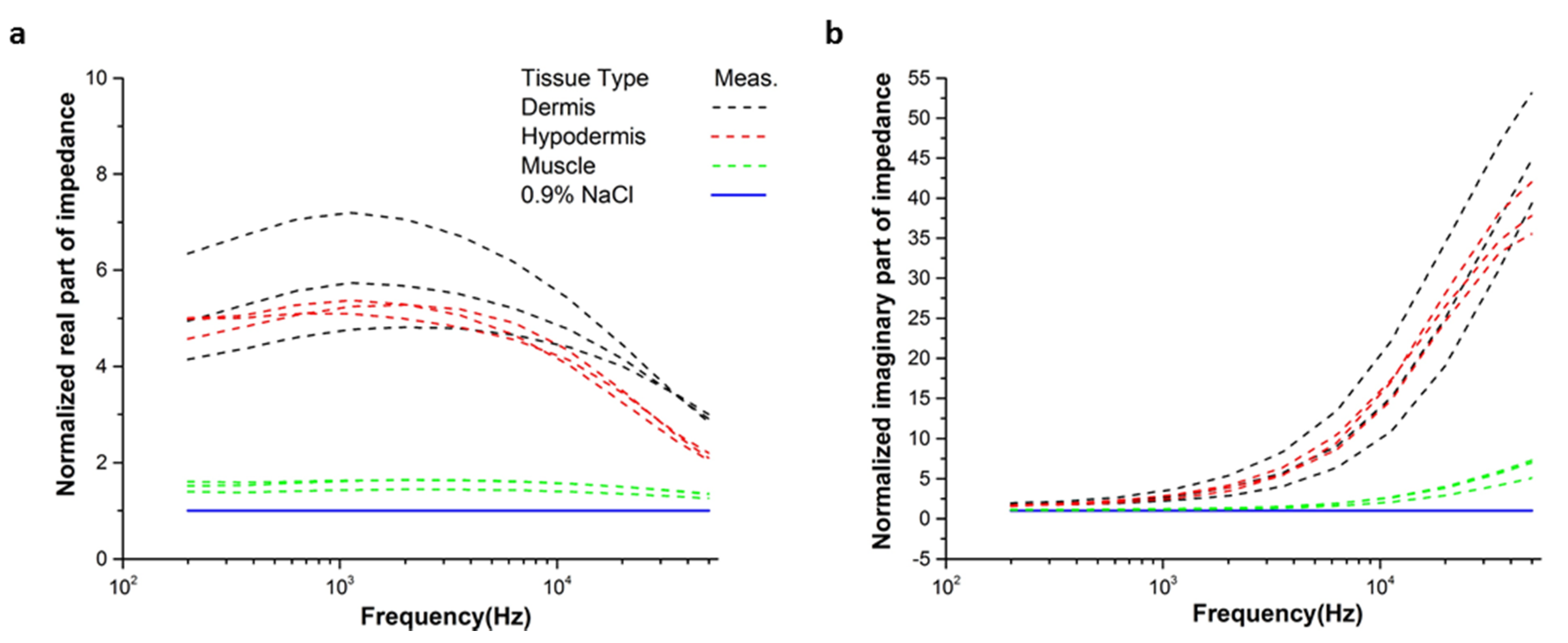
3.2. Impedance Characterization of Porcine Tissue Using the Needle

The segmental layers of pork tissue used for the experiment, including the dermis, hypodermis, and muscle is shown in Figure 3. From the ultrasound image of the pork tissue, the structure and thickness of the tissue layers in the pork meat could be found. With the aid of ultrasonography, the tip of the monopolar injection needle was successfully inserted and positioned in the specific tissue layer. The electrical impedance data of the tissue layers were measured while the needle position was observed in real-time by ultrasonography.
Figure 4 shows the real and imaginary part of the measured impedance in the tissue layers of the porcine, in the frequency range of 200 Hz to 50 kHz. The real part of the impedance in the case of the dermis layer was higher than that of muscle and hypodermis in the measurement frequency due to the presence of lipid components with high resistivity in the dermal tissue [22]. Whereas, the muscle tissue showed higher conductivity compared to other tissue layers [11]. The impedance of the saline (0.9% NaCl) solution, which has similar conductivity of the synovial fluid [23], was lower than other tissue layers.
The imaginary part of the impedance measured in the tissue type could be discriminated at frequencies higher than 10 kHz at which the magnitude of the electrode impedance decreased enough to be ignored. The electrode impedance governed the total impedance magnitude at low frequencies because of the capacitive reactance of the electrode interface, which can be described using the constant phase element (CPE) as follows:
CPE el = 1 T ( j ω ) P ,
where j is the imaginary unit, ω is the angular frequency, T and p are the parameters of the CPE.
At enough high frequencies, the total impedance is contributed to by not only the extra cellular resistance but also the cell membrane and intracellular resistance [24]. The result of Figure 4b showed that the reactance magnitude of the muscle was higher than other tissues. The relative permittivity of the muscle was higher than the hypodermis [25].
The measured impedance spectra of muscle, hypodermis, and dermis were well fitted by the equivalent circuit model shown in the inset of Figure 4b. The equivalent circuit consists of Rin and Rex for the intra- and extracellular resistance respectively, Cm for the membrane capacitance, and CPEel for electrode impedance. From the fitting analysis, the extrapolated values of the circuit parameters for each tissue type are arranged in Table 1 with χ2 showing the precision of the data fitting.
The measured impedance of tissue using the monopolar needle was characterized by the total complex impedance characteristics of each tissue layer. When the position of the needle was close to the neighbored tissue, the impedance of the tissue was more affected by the electrical properties of the neighbored tissue. However, the impedance characteristics of the different tissue layer could be significantly separated. The impedance measurement with monopolar injection needle could not analyze the impedance characteristics of each tissue layer from the total measured impedance data. Despite the limitation of the monopolar needle that the measured impedance was varied with relative distance between the two electrodes and the depth of the needle electrode, it was able to distinguish the impedance of the dermis, hypodermis, or muscle.

3.3. Impedance Monitoring of the Needle Positioning

The extrapolation of tissue parameters from the fitting analysis with measured impedance spectra, for example, Rex, Rin, and Cm may provide better discrimination for tissue types. This fitting analysis needs to measure the impedance at least three different frequencies and to implement the algorithm for extrapolating the circuit parameters. One limitation for this is that the needle should not be moved until the fitting analysis is completely finished. However, we focused on the real-time monitoring of the needle positioning, which requires fast signal analysis and processing, and monitored the impedance at a fixed frequency at a sampling rate of 19 S/s. With this high speed of impedance measurement, the dynamic needle position in different tissues layer could be detected in real-time.
The target of the intra-articular injection needle is synovial fluid which has a similar conductivity to the saline (0.9% NaCl) solution [23]. Further, saline is commonly used as a joint irrigation solution. Therefore, we investigated the impedance value of tissue layers relative to the saline. The impedance spectra at three different positions in the specific tissue layer were measured and normalized with respect to the values of the saline (0.9% NaCl) solution in the frequency range of 200 Hz to 50 kHz by using Equation (2).
Z norm = Z tissue Z NaCl .
From the normalized data of Figure 5, it is observed that the real parts of the impedance of tissues were significantly discriminated from each other at the frequencies higher than 10 kHz. Considering the variation of the real parts of the impedance of the tissue layer decreased with the increase in frequency, we have selected a frequency of 50 kHz for the real-time monitoring of the needle position in the tissue.
Figure 6a presents the Student’s t-test (one-way ANOVA) to evaluate the difference between the real part of the impedance value between different tissue types (n = 3) at 50 kHz. The results show that the type of tissue compartment in the pork meat could be significantly discriminated from each other (p < 0.001) using the monopolar injection needle and DFT-based impedance measurement system. The deviation between impedance measurements in each layer of different pork tissues at 50 kHz is under 3.7%. While in Figure 6b, the monopolar injection needle was progressed into different tissue layers of the pork, and the real part of impedance at 50 kHz was recorded. When the needle tip was positioned in the dermis from 0 s to 3.4 s, the measured impedance was higher than other tissue layers because of the low conductive nature of the dermis tissue and sweat dust, hair follicles in the dermis tissue [26]. As the needle tip was progressed into the hypodermis and paused for 4.04 s to 19.5 s to obtain the impedance of the hypodermis. As expected, the real part of the impedance at 50 kHz was significantly decreased due to the high conductivity of the hypodermis as compared to dermis [26]. Once the needle tip reached the muscle, it was paused for a period of 20.7 s to 36.9 s. The impedance value decreased again corresponding to the lower resistance of the muscle than other tissues layers [11]. When the needle was withdrawn from the muscle compartment to hypodermal tissue, the needle was paused for 37.4 s to 52.7 s, where the real part of impedance value was increased due to the high resistive properties of the hypodermis tissue as compared to muscle. And at last, when the needle was withdrawn into the dermal tissue, it was again paused for a period of 52.8 s to 70.09 s to measure the impedance. The tissue impedance was again increased due to the resistive structure of dermis tissue.
For future work, the current detection method needs to be improved by providing information about the lateral and spatial position of the needle tip. For this, the distribution of the electric fields or sensitivity fields in the complex tissue structure determined by different electrode configuration is required to be investigated. Several research groups [6,17] reported the finite element simulation of the electric fields surrounding the needle tip in different tissue models. The electrical impedance tomography using a multi-electrode array is expected to provide the lateral and spatial information of the needle [27,28]. Finally, the feasibility of the intra-articular injection therapy based on the impedance monitoring with the monopolar injection needle and the algorithm to detect the target tissue will be tested in an animal model and clinical trials.

4. Conclusions

For better intra-articular injection therapy, the electrical impedance measurement based positioning of the monopolar injection needle tip was suggested, and its feasibility was tested on pork tissue. The electrical impedance spectra of the tissue layer measured in the frequency range of 200 Hz to 50 kHz were characterized by using the designed equivalent circuit model. The electrical impedance monitoring with the monopolar injection needle showed significant discrimination of the tissue type among dermis, hypodermis, and muscle (p-value < 0.0001). Based on the result, the DFT-based impedance measurement system with monopolar injection needle is expected to be used as complementary to the image guidance for the accurate positioning of the tip in the target tissue and for the efficient intra-articular injection therapy.

Author Contributions

A.M.A.: Design hardware and software, Conceptualization, Methodology, Validation, Formal analysis, Data curation, Investigation, Writing—Original draft. J.K.: Conceptualization, Methodology. T.K.: Conceptualization, Methodology, Resources. K.D.P.: Conceptualization, Methodology, Resources, Writing —review. S.C.: Conceptualization, Methodology, Resources, Writing—review and editing, Visualization, Supervision, Project administration, Funding acquisition.

Funding

This research was supported by the Gachon University Gil Medical Center (Grant number: 2017-08) and the National Research Foundation of Korea (No. NRF-2017R1D1A1A09000712, 2018R1C1B6009385, 2018M3A9F1023690).

Conflicts of Interest

The author declares that there is no conflict of interest regarding the publication of this paper.

References

  1. Na, K.S. Ultrasound-guided intra-articular injections. Korean J. Med. 2015, 89, 654–662. [Google Scholar] [CrossRef]
  2. Sun, S.D.; Chang, B.K.; Moon, S.H. Ultrasound-Guided intervention in cervical spine. J. Korean Orthop. Ultrasound Soc. 2015, 50, 77–92. [Google Scholar] [CrossRef]
  3. Kalvøy, H.; Nordbotten, B.; Tronstad, C.; Martinsen, Ø.G.; Grimnes, S. Impedance properties of stainless steel needle electrodes. In Proceedings of the World Congress on Medical Physics and Biomedical Engineering, Munich, Germany, 7–12 September 2009; Springer: Berlin, Germany, 2009; pp. 380–383. [Google Scholar]
  4. Grimnes, S.; Martinsen, Ø.G. Bioimpedance and Bioelectricity, Basics; Academic Press: San Diego, CA, USA, 2000. [Google Scholar]
  5. Yun, J.; Kim, H.W.; Lee, J.H. Improvement of depth profiling into biotissues using micro electrical impedance spectroscopy on a needle with selective passivation. Sensors 2016, 16, 2207. [Google Scholar] [CrossRef] [PubMed]
  6. Kalvøy, H. Needle Guidance in Clinical Applications Based on Electrical Impedance. Ph.D. Thesis, Department of Physics, University of Oslo, Oslo, Norway, 2010. [Google Scholar]
  7. Trainito, C. Study of Cell Membrane Permeabilization Induced by Pulsed Electric Field-Electrical Modeling and Characterization on Biochip. Ph.D. Thesis, Univeristẻ Paris-Saclay, Saint-Aubin, France, 2015. [Google Scholar]
  8. Vydyanathan, A.; Kosharskyy, B.; Singh, N.; Gritsenko, K.; Kim, R.S.; Wang, D.; Shaparin, N. The use of electrical impedance to identify intraneural needle placement in human peripheral nerves: A study on amputated human limbs. Anesth. Analg. 2016, 123, 228–232. [Google Scholar] [CrossRef] [PubMed]
  9. Bera, K.T. Biolelectrical impedance methods for noninvasive health monitoring. J. Med. Eng. 2014, 2014, 381251. [Google Scholar] [CrossRef] [PubMed]
  10. Dean, D.A.; Ramanathan, T.; Machoda, D.; Sundararajan, R. Electrical impedance spectroscopy study of biological tissues. J. Electrost. 2008, 66, 165–177. [Google Scholar] [CrossRef] [PubMed] [Green Version]
  11. Sharp, J.; Bouazza-Marouf, K.; Noronha, D.; Gaur, A. Tissue type determination by impedance measurement: A bipolar and monopolar comparison. Saudi J. Anesth. 2017, 11, 15–20. [Google Scholar] [Green Version]
  12. Yun, J.; Kang, G.; Park, Y.; Kim, H.W.; Cha, J.; Lee, J. Electrochemical impedance spectroscopy with interdigitated electrodes at the end of hopermic needle for depth profiling of biotissues. Sens. Actuators B Chem. 2016, 237, 984–991. [Google Scholar] [CrossRef]
  13. Kang, G.; Seo, S.; Yun, J.; Lee, J.H. A novel electrical needle with microelectrodes for real-time impedance measurement of biotissues. In Proceedings of the 17th International Conference on Miniaturized Systems for Chemistry and Life Sciences, Freiburg, Germany, 27–31 October 2013; pp. 847–849. [Google Scholar]
  14. Kalvøy, H.; Frich, L.; Grimnes, S.; Martinsen, Ø.G.; Hol, P.K.; Stubhaug, A. Impedance-based tissue discrimination for needle guidance. Physiol. Meas. 2009, 30, 129–140. [Google Scholar] [CrossRef] [PubMed]
  15. Park, J.; Choi, W.M.; Kim, K.; Jeong, W.I.; Seo, J.B.; Park, I. Biopsy needle integrated with electrical impedance sensing microelectrode array towards real-time needle guidance and tissue discrimination. Sci. Rep. 2018, 8, 264. [Google Scholar] [CrossRef]
  16. Cheng, Z.; Davies, B.L.; Caldwell, D.G.; Barresi, G.; Xu, Q.; Mattos, L.S. A hand-held robotic device for peripheral intravenous catheterization. Proc. Inst. Mech. Eng. Part H. J. Eng. Med. 2017, 231, 1165–1177. [Google Scholar] [CrossRef]
  17. Halonen, S.; Kari, J.; Ahnoen, P.; Kronström, K.; Hyttinen, J. Real-Time bio impedance-based biopsy needle can identify tissue type with high spatial accuracy. Ann. Biomed. Eng. 2019, 47, 836–851. [Google Scholar] [CrossRef]
  18. Deneris, Z.; Pe’a, D.E.; Furse, C.M. A layered pork model for subdermal antenna tests at 433 MHz. IEEE J. Electromagn. RF Microw. Med. Biol. 2019, 3, 171–176. [Google Scholar] [CrossRef]
  19. Analog Devices, ADuCM350 Datasheet and Product Info. Available online: https://www.analog.com/en/products/aducm350.html (accessed on 8 August 2018).
  20. Analog Devices, ADuCM350 Application Note AN-1271. Available online: https://www.analog.com/media/en/technical-documentation/application-notes/an-1271.pdf (accessed on 31 August 2018).
  21. Sajib, S.Z.K.; Lee, M.B.; Kim, H.J.; Woo, E.J.; Kwon, O.I. Extracellular total electrolyte concentration imaging for electrical brain stimulation (EBS). Sci. Rep. 2018, 8, 290. [Google Scholar] [CrossRef] [PubMed]
  22. Johnsen, G.K. Skin Electrical Properties and Physical Aspects of Hydration of Keratinized Tissues. Ph.D. Thesis, University of Oslo, Oslo, Norway, 2010. [Google Scholar]
  23. Amin, A.K.; James, H.S.; Simpson, A.H.R.W.; Hall, A.C. Increasing the Osmolarity of joint irrigation solutions may avoid injury to cartilage: A. pilot study. Clin. Orthop. Relat. Res. 2010, 468, 875–884. [Google Scholar] [CrossRef] [PubMed]
  24. Mosgaard, L.D.; Zecchi, K.A.; Heimburg, T.; Budvytyte, R. The effect of the nonlinearity of the response of lipid membranes to voltage perturbations on the interpretation of their electrical properties. A new theoretical description. Membranes 2015, 5, 495–512. [Google Scholar] [CrossRef] [PubMed]
  25. Vallejo, M.; Recas, J.; del Valle, P.; Ayala, J. Accurate human tissue characterization for energy-efficient wireless on-body communications. Sensors 2013, 13, 7546–7569. [Google Scholar] [CrossRef] [PubMed]
  26. Yang, K.; Abbasi, Q.H.; Chopra, N.; Munoz, M.; Hao, Y.; Alomainy, A. Effects of non-flat interfaces in human skin tissues on the in-vivo tera-hertz communication channel. Nano Commun. Netw. 2016, 8, 16–24. [Google Scholar] [CrossRef]
  27. Meroni, D.; Maglioli, CC.; Bovio, D.; Greco, F.G.; Andrea Aliverti, A. An electrical impedance tomography (EIT) multi-electrode needle-probe device for local assessment of heterogeneous tissue impeditivity. In Proceedings of the 39th Annual International Conference of the IEEE Engineering in Medicine and Biology Society (EMBC), Jeju Island, Korea, 11–15 July 2017; pp. 1385–1388. [Google Scholar] [CrossRef]
  28. Meir, A.; Rubinsky, B. Electrical impedance tomography of electrolysis. PLoS ONE 2015, 10, e0126332. [Google Scholar] [CrossRef] [PubMed]
Figure 1. (a) Experimental setup for impedance characterization of pork tissue including ADuCM350 discrete Fourier transform (DFT) based impedance measurement device (1), C program window (2), LabVIEW GUI (3), ultrasound transducer (4), ultrasound image display (5), pork tissue (6), monopolar needle injection working electrode (7), and Ag/AgCl counter electrode (8), (b) Schematic of the electrode configuration of the impedance measurement circuit.
Applsci 09 04049 g001
Figure 2. (a,c,e) Real and (b,d,f) imaginary part of the impedance spectra of the resistor–resistor–capacitor (RRC) circuit measured with respect to different (a,b) C1, (c,d) R1, or (e,f) R2 by the DFT-impedance measurement system (ADuCM350) in comparison to the commercialized product (SP-200).
Applsci 09 04049 g002
Figure 3. (a) Pork tissue used for the experiment, (b) ultrasound image of the pork tissue showing the needle location in muscle layer indicated by the red colored boundary, and (c) the different thickness of the tissue layers indicated by the red arrows.
Applsci 09 04049 g003
Figure 4. (a) Real and (b) imaginary part of the impedance spectra measured in the pork tissue layer at frequencies from 200 Hz to 50 kHz together with the fitted lines using the equivalent circuit model.
Applsci 09 04049 g004
Figure 5. Normalized (a) real and (b) imaginary part of the impedance with respect to the values of the saline (0.9% NaCl) solution from the measured spectra at three different positions in each tissue type.
Applsci 09 04049 g005
Figure 6. (a) Student’s t-test of the real part of impedance at 50 kHz between tissue layers of three different pork tissue samples, (b) real-time monitoring of the pork tissue impedance at 50 kHz during the movement of the monopolar injection needle into different tissue layers.
Applsci 09 04049 g006
Table 1. Extrapolated value of the circuit parameters from the fitting analysis against the experimentally measured impedance spectra shown in Figure 4.
Tissue TypeRex(Ω)Rin(Ω)Cm(F)CPEelχ2
PT(Ohm−1 sP)
Dermis7426 ± 223.23608.3 ± 766.34.81 × 10−10 ± 1.1 × 10−100.49 ± 0.093.02 × 10−06 ± 1.3 × 10−060.001
Hypodermis6786.6 ± 706.52622.6 ± 155.57.25 × 10−10 ± 6.69 × 10−110.5 ± 0.052.86 × 10−06 ± 7.61 × 10−070.001
Muscle2437.6 ± 140.46750.6 ± 837.54.96 × 10−10 ± 5.14 × 10−110.76 ± 0.0117.7 × 10−07 ± 3.86 × 10−080.0003
Each datum point represents the average of the analysis of triplicate values with standard deviation (n = 3).

