Article

Free Vibration of a Taut Cable with Two Discrete Inertial Mass Dampers

1
International Joint Research Lab for Eco-Building Materials and Engineering of Henan Province, North China University of Water Resources and Electric Power, Zhengzhou 450045, China
2
Key Laboratory of Concrete and Prestressed Concrete Structure of Ministry of Education, Southeast University, Nanjing 210096, China
*
Author to whom correspondence should be addressed.
Appl. Sci. 2019, 9(18), 3919; https://doi.org/10.3390/app9183919
Submission received: 15 August 2019 / Revised: 8 September 2019 / Accepted: 12 September 2019 / Published: 18 September 2019

Abstract

:
Recently, inertial mass dampers (IMDs) have shown superior control performance over traditional viscous dampers (VDs) in vibration control of stay cables. However, a single IMD may be incapable of providing sufficient supplemental modal damping to a super-long cable, especially for the multimode cable vibration mitigation. Inspired by the potential advantages of attaching two discrete VDs at different locations of the cable, arranging two external discrete IMDs, either at the opposite ends or the same end of the cable is proposed to further improve vibration mitigation performance of the cable in this study. Complex modal analysis based on the taut-string model was employed and extended to allow for the existence of two external discrete IMDs, resulting in a transcendental equation for complex wavenumbers. Both asymptotic and numerical solutions for the case of two opposite IMDs or the case of two IMDs at the same end of the cable were obtained. Subsequently, the applicability of asymptotic solutions was then evaluated. Finally, parametric studies were performed to investigate the effects of damper positions and damper properties on the control performance of a cable with two discrete IMDs. Results showed that two opposite IMDs can generally provide superior control performance to the cable over a single IMD or two IMDs at the same end. It was also observed that attaching two IMDs at the same end of the cable had the potential to achieve significant damping improvement when the inertial mass of the IMDs is appropriate, which seems to be more promising than two opposite IMDs for practical application.

1. Introduction

With the flourishing development of materials and construction technologies, civil engineering structures are becoming larger, lighter, and more flexible, especially for long-span bridges. Cable-stayed is a common option for bridges in the medium to long-span ranges due to its unique structural formation, economic advantage, and esthetic value [1]. However, as important load-bearing components of cable-stayed bridges, stay cables are highly susceptible to dynamic excitations due to their high flexibility and low intrinsic damping [2,3]. Frequent and excessive amplitude cable vibrations may lead to fatigue failure of cables. These problems may inevitably shorten the service life and cause the risk of losing public confidence in cable-stayed bridges. To guarantee structural safety, several solutions have been proposed to dampen cable vibrations, which include modifying aerodynamic surface of cables [4], connecting cables together via cross tie [5], and attaching external dampers on cables [6,7,8,9].
Though these practical measures have been well applied in the field, each has its own shortcomings. Changing the surface of the cable is difficult to implement for retrofit and may increase drag forces at high wind velocities [10]. Cross-ties are incapable of direct energy dissipation and make the aesthetics of cable-stayed bridges deteriorate [11]. Compared to the two methods above, attaching external dampers on the cable seems to be more promising. Nevertheless, the installation location of a passive viscous damper is typically restricted to within a few percentage points of the cable length from the cable anchorage [12]. As expected, passive viscous dampers cannot provide sufficient damping to eliminate vibrations for super-long cables, such as the Sutong Bridge, with cables nearly 600 m long. Moreover, the results based on both theoretical and experimental studies indicated that the existence of the cable sag [13,14], the cable flexural rigidity [15,16], the damper stiffness [17], and the damper support stiffness [18] or their coexistence [19,20,21,22,23] would have adverse impacts on the efficiency of passive viscous dampers.
An active damper can produce a force-deformation relationship with the negative-stiffness behavior that benefits damper efficiency when the linear quadratic regulator (LQR) algorithm is employed [24,25]. However, active dampers often require high power sources beyond practical limits and are thus rarely used for cable vibration mitigation in real bridges. Alternatively, semiactive dampers, which can produce similar hysteresis and achieve control performance comparable to that of active dampers, were proposed [26,27,28,29]. For instance, the semiactive control based on magnetorheological dampers has been successfully applied on the Dongting Lake Bridge [30], Binzhou Bridge [31], and Sutong Bridge [32]. Compared to active dampers, semiactive dampers require less power. Nevertheless, possible implementations of semiactive dampers on site still require an external stable power supply, a sensing system, and a controller, which seems to be complicated and costly. This fact has inspired researchers to introduce a negative stiffness mechanism into passive dampers to mitigate cable vibrations.
Recently, several representative passive dampers with negative stiffness mechanisms, including pre-spring negative stiffness dampers (pre-spring NSDs) [33,34] and magnetic negative stiffness dampers (magnetic NSDs) [35,36], have been successfully developed. Negative stiffness dampers have well demonstrated to be capable of providing superior damping over that of traditional passive viscous dampers [37,38,39]. However, extremely large passive negative stiffness may make the NSD lose its stability. Alternatively, an inerter has the potential to provide similar negative stiffness without a stability problem [40]. Many inerter-based absorber layouts have been proposed, and their control performance advantages have been proven for civil engineering structures [41,42,43,44,45,46,47,48,49,50,51,52,53,54,55,56,57,58,59]. As for the vibration suppression of cables, typical inertial mass dampers (IMDs) [60,61,62,63,64,65] and tuned inerter dampers [66,67] were well developed, and their significant improvement on the achievable modal damping ratio of the cable was verified via both theoretical and experimental investigations.
With the increasing cable length, it may be difficult to attain a desired level of supplemental modal damping with a single damper or a pair of dampers installed near the deck anchorage. Hence, some hybrid techniques have been further proposed. The idea of combining external dampers with cross-ties for cable vibration control was considered, which not only addresses the deficiencies of these two commonly used countermeasures but also still retains their respective merits [68,69,70,71,72,73]. A hybrid damper system, combining a viscous damper and a tuned mass damper, can overcome the shortcomings of single type of dampers and improve effectiveness and robustness in suppressing cable vibration [74]. In addition, application of two viscous dampers or two high-damping rubber dampers at different locations of a cable was proposed [75,76,77]. The results have shown that when two viscous dampers are installed at opposite ends of a cable, their damping effects are approximately the sum of the contributions from each damper [77]. However, when they are at the same cable end, the maximum modal damping ratio of the cable is determined by a single damper at the further distance, indicating no benefits over a single damper configuration [77].
Inspired by the potential advantages of attaching two external discrete viscous dampers (VDs) on a cable, this study aimed to evaluate the feasibility of a cable with two discrete IMDs, either on the opposite end or on the same end of the cable, to improve the vibration mitigation performance of the cable in each mode. Complex modal analysis based on the taut-string model was employed and extended to allow for the existence of two external discrete IMDs. The formulation for free vibration of a taut cable with two discrete IMDs was established, and corresponding complex wavenumber equations of free damped vibration were derived. The asymptotic and numerical solutions of the wavenumber equation were obtained, and the applicability of asymptotic solutions was then evaluated. Finally, parametric studies were performed to investigate the effects of damper positions and damper properties on the control performance of the cable with two discrete IMDs.

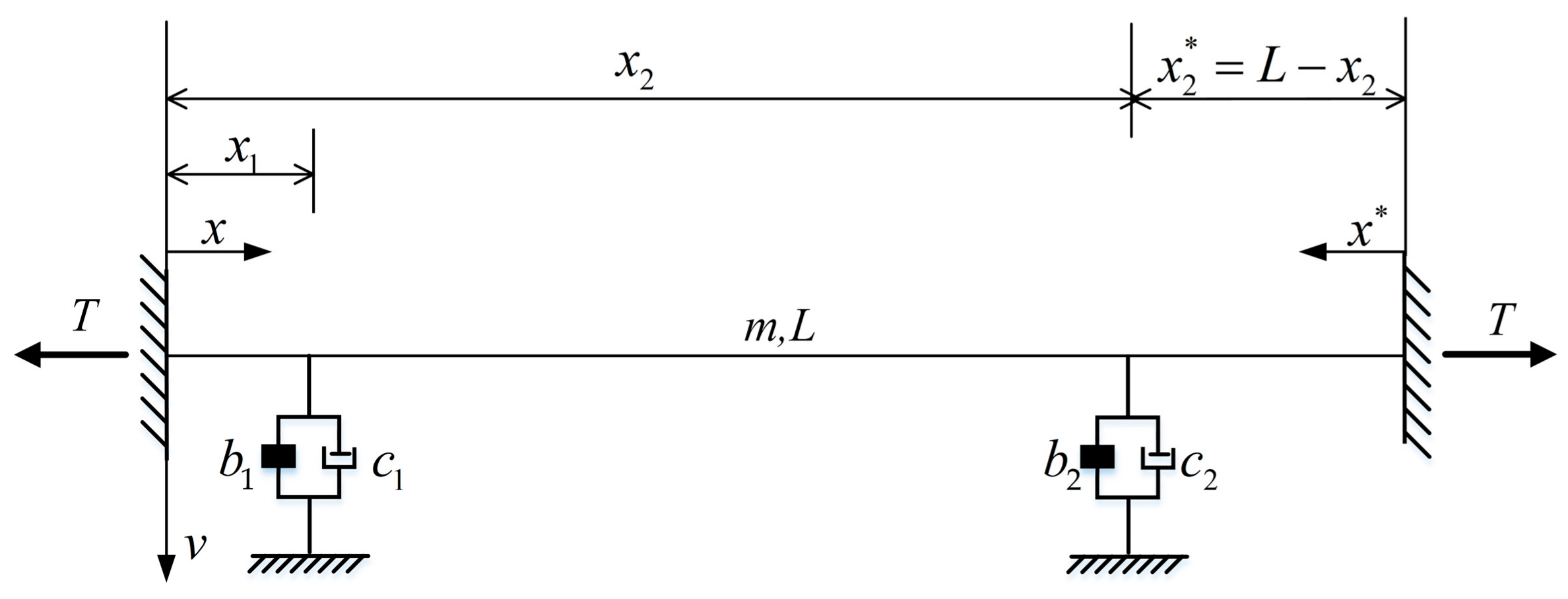
2. Formulation of the Cable–IMD System

A taut cable with two transversely attached inertial mass dampers is shown in Figure 1. The length, the mass per unit length, and the tension of the cable are L, m, and T, respectively. The coordinate system defines that the x-axis and the v-axis are along the cable chord and the transverse direction, respectively. x * = L x represents the coordinate from the right end of the cable. Two discrete IMDs are respectively installed at distances x 1 and x 2 from the left end of the cable ( x 2 x 1 ). The distance between the right IMD and the right end is denoted as x 2 * = L x 2 . The damping coefficient and inertial mass of the jth IMD are denoted as c j and b j (j = 1, 2), respectively. The equation of motion of the cable–IMD system is given by:
T 2 v x 2 m 2 v t 2 = j = 1 2 F IMD j ( t ) δ ( x x j ) ,
where v ( x , t ) is the cable transverse displacement and δ ( · ) is delta function to specify the location of the damping force F IMD j at x = x j .
Under free vibration, applying separation of variables, the cable transverse displacement and the IMD force can be respectively expressed as:
v ( x , t ) = v ˜ ( x ) e i ω t , F IMD j ( t ) = F ˜ IMD j e i ω t
where i 2 = 1 , ω is a complex natural frequency of the cable, and v ˜ ( x ) is the corresponding complex mode shape. To find v ˜ ( x ) , the cable can be considered as a multispan structure connected at the damper locations [77]. Substituting Equation (2) into Equation (1), v ˜ ( x ) in each span needs to satisfy a homogeneous equation [77]:
d 2 v ˜ d x 2 + β 2 v ˜ = 0     0 x x 1 x 1 x x 2 0 x * x 2 * ,
where β = ω m / T refers to the wavenumber.
Applying boundary conditions at cable ends, i.e., v ˜ ( 0 ) = v ˜ ( L ) = 0 , and the transverse displacement compatibility conditions at damper locations, i.e., v ˜ ( x 1 ) = v 1 ˜ , v ˜ ( x 2 * ) = v 2 ˜ , the general solution of Equation (3) can be further written in the form [77]:
v ˜ ( x ) = v ˜ 1 sin β x sin β x 1 0 x x 1 v ˜ 1 sin β ( x 2 x ) sin β ( x 2 x 1 ) + v ˜ 2 sin β ( x x 1 ) sin β ( x 2 x 1 ) x 1 x x 2 v ˜ 2 sin β x * sin β x 2 * 0 x * x 2 * ,
where v ˜ j is the mode shape amplitude at the jth damper location.
At damper locations, there is:
T ( d v d x | x j + d v d x | x j ) = F ˜ IMD j ( t ) .
Substituting Equation (4) into Equation (5), it yields:
cot β x 1 + cot ( x 2 x 1 ) v ˜ 2 v ˜ 1 1 sin β ( x 2 x 1 ) = F ˜ IMD 1 / T β v ˜ 1 v ˜ 2 v ˜ 1 1 sin β ( x 2 x 1 ) + cot β ( x 2 x 1 ) + cot β x 2 * = F ˜ IMD 2 / T β v ˜ 1 .
Substituting v ˜ 1 / v ˜ 2 from the second one into the first one of Equation (6) and rearranging, the characteristic equation of the wavenumber β is derived as:
( cot β x 1 + F ˜ IMD 1 / T β v ˜ 1 ) ( cot β x 2 * + F ˜ IMD 2 / T β v ˜ 2 ) + ( cot β x 1 + F ˜ IMD 1 / T β v ˜ 1 + cot β x 2 * + F ˜ IMD 2 / T β v ˜ 2 ) cot β ( x 2 x 1 ) = 1

3. Two Opposite IMDs

3.1. The Wavenumber Equation

The damper force of the jth IMD can be expressed as [45]:
F IMD j ( t ) = b j 2 v ( x j , t ) t 2 + c j v ( x j , t ) t or F ˜ IMD j = b j ω 2 v ˜ j + c j ω v ˜ j .
When two IMDs are installed at different ends of the cable, substituting Equation (8) into Equation (7) and using trigonometric relations, Equation (7) can be rearranged to the form relating to x 1 and x 2 * as:
tan β L = A 1 + i B 1 C 1 + i D 1 ,
A 1 = χ 1 sin 2 β x 1 χ 2 sin 2 β x 2 * + ( χ 1 χ 2 η 1 η 2 ) sin β x 1 sin β x 2 * sin β ( x 1 + x 2 * ) ,
B 1 = η 1 sin 2 β x 1 + η 2 sin 2 β x 2 * ( χ 1 η 2 + χ 2 η 1 ) sin β x 1 sin β x 2 * sin β ( x 1 + x 2 * ) ,
C 1 = 1 χ 1 sin β x 1 cos β x 1 χ 2 sin β x 2 * cos β x 2 * + ( χ 1 χ 2 η 1 η 2 ) sin β x 1 sin β x 2 * cos β ( x 1 + x 2 * )
D 1 = η 1 sin β x 1 cos β x 1 + η 2 sin β x 2 * cos β x 2 * ( χ 1 η 2 + χ 2 η 1 ) sin β x 1 sin β x 2 * cos β ( x 1 + x 2 * )
where η j = c j m T and χ j = b j ω m T represent the dimensionless damping coefficient and the dimensionless inertial mass of the jth IMD, respectively.
The form of Equation (9) is suitable for solutions, either for asymptotic solutions or numerical solutions by iteration.

3.2. Asymptotic Solution

The following assumptions are introduced [12,17,77]: (1) The locations of IMDs are very close to the ends, i.e., x 1 , x 2 * L ; (2) the wavenumber β n of each mode n (n = 1, 2, …) has a small perturbations Δ β n = β n β n 0 from the undamped value β n 0 = n π / L . The assumptions above lead to the following approximations:
tan ( β n L ) β n L n π    sin ( β n x 1 ) β n 0 x 1    sin ( β n x 2 * ) β n 0 x 2 *    cos ( β n x 1 ) cos ( β n x 2 * ) = 1 .
The asymptotic formula for the wavenumber β n takes the form:
β n L n π + β n 0 E 1 + i F 1 G 1 + i H 1 ,
E 1 = b 1 ¯ x 1 b 2 ¯ x 2 * + ( b 1 ¯ b 2 ¯ c 1 ¯ c 2 ¯ ) ( x 1 + x 2 * ) ,
F 1 = c 1 ¯ x 1 + c 2 ¯ x 2 * ( b 1 ¯ c 2 ¯ + b 2 ¯ c 1 ¯ ) ( x 1 + x 2 * ) ,
G 1 = 1 b 1 ¯ b 2 ¯ + ( b 1 ¯ b 2 ¯ c 1 ¯ c 2 ¯ ) ( x 1 + x 2 * ) ,
H 1 = c 1 ¯ + c 2 ¯ ( b 1 ¯ c 2 ¯ + b 2 ¯ c 1 ¯ ) ( x 1 + x 2 * ) ,
where c 1 ¯ = η 1 β n 0 x 1 and c 2 ¯ = η 1 β n 0 x 2 * represent dimensionless damping coefficient groups, while b 1 ¯ = χ 1 β n 0 x 1 and b 2 ¯ = χ 2 β n 0 x 2 * represent dimensionless inertial mass groups.
The complex eigen-frequency corresponding to the wavenumber β n is denoted as ω n . The nth supplemental modal damping radio of a cable ξ n can be obtained by [17]:
ξ n = Im [ ω n ] ω n = Im [ β n ] β n Im [ Δ β n ] β n 0 .
Substituting Equation (11) into Equation (12), the asymptotic supplemental modal damping ratio of the cable is finally derived as:
ξ n c 1 ¯ ( 1 b 1 ¯ ) 2 + ( c 1 ¯ ) 2 x 1 L + c 2 ¯ ( 1 b 2 ¯ ) 2 + ( c 2 ¯ ) 2 x 2 L .
If two identical IMDs are symmetrically installed at the cable for practical implementation, some simplifications in the notation can be introduced, i.e., x = x 1 = L x 2 = x 2 * , b 1 = b 2 = b , χ 1 = χ 2 = χ , b 1 ¯ = b 2 ¯ = b ¯ , c 1 = c 2 = c , η 1 = η 2 = η , and c 1 ¯ = c 2 ¯ = c ¯ . Equation (13) can be further simplified as:
ξ n = 2 c ¯ ( 1 b ¯ ) 2 + ( c ¯ ) 2 x 1 L .

3.3. Numerical Solution

The numerical solution of the wavenumber β n to Equation (9) is obtained by the fixed point iteration [12,14], which starts from the undamped wavenumber β n 0 . Substituting β n 0 into the right side of the Equation (9), the resulting value β n 1 is obtained. Similarly, with current estimate β n k , k = 1 , 2 , 3 ... , a new estimate β n k + 1 will be derived. The iterative scheme is given by:
β n k + 1 L = n π + arctan A ¯ 1 + i B ¯ 1 C ¯ 1 + i D ¯ 1 ,
A ¯ 1 = χ 1 sin 2 β n k x 1 χ 2 sin 2 β n k x 2 * + ( χ 1 χ 2 η 1 η 2 ) sin β n k x 1 sin β n k x 2 * sin β n k ( x 1 + x 2 * ) ,
B ¯ 1 = η 1 sin 2 β n k x 1 + η 2 sin 2 β n k x 2 * ( χ 1 η 2 + χ 2 η 1 ) sin β n k x 1 sin β n k x 2 * sin β n k ( x 1 + x 2 * ) ,
C ¯ 1 = 1 χ 1 sin β n k x 1 cos β n k x 1 χ 2 sin β n k x 2 * cos β n k x 2 * + ( χ 1 χ 2 η 1 η 2 ) sin β n k x 1 sin β n k x 2 * cos β n k ( x 1 + x 2 * )
D ¯ 1 = η 1 sin β n k x 1 cos β n k x 1 + η 2 sin β n k x 2 * cos β n k x 2 * ( χ 1 η 2 + χ 2 η 1 ) sin β n k x 1 sin β n k x 2 * cos β n k ( x 1 + x 2 * )
Finally, the supplemental modal damping ratio of a cable with two opposite IMDs can be calculated by Equation (12) after solving the wavenumber β n .

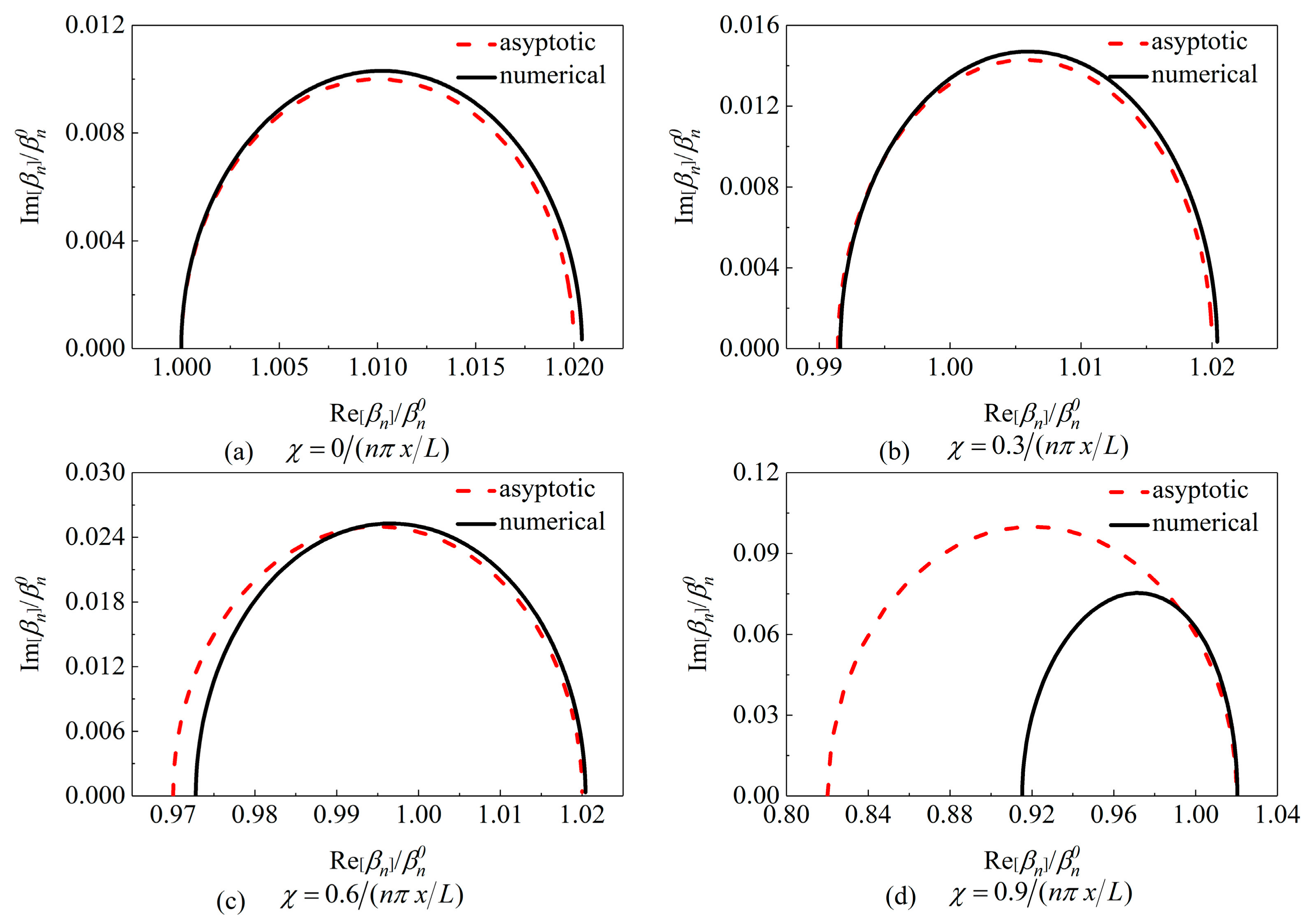
3.4. Comparison of Asymptotic and Numerical Solutions

Figure 2 shows the comparison of asymptotic and numerical complex wavenumbers of a cable with two symmetric identical IMDs for various inertial masses. Two IMDs are assumed to be respectively installed at distances x 1 of 1%L and x 2 of 99%L from the left end of the cable, i.e., x = x 1 = x 2 * = L x 2 = 1 % L . When inertial masses remain constant and damping coefficients of two IMDs increase from zero to infinity, the loci, which nearly trace a semicircular contour, start from the undamped wavenumber and finally attach to the real axis. According to Equation (12), the damping properties result from the imaginary part of the wavenumber. Maximum supplemental modal damping can be obtained at the top point of the semicircle [17]. The diameter of the loci is quite small but increases with the increase of the inertial masses of IMDs, indicating that two symmetric identical IMDs have slight influences on the damped frequency of the cable and can achieve higher supplemental modal damping ratios than traditional VDs. By comparing asymptotic and numerical complex wavenumbers, it is seen that two results coincide well with each other for small or moderate inertial mass ( χ 0.6 / ( n π x / L ) ) adopted in the IMDs. Nevertheless, the results deviate significantly from each other when the big inertial mass ( χ = 0.9 / ( n π x / L ) ) shown in Figure 2d is adopted. Hence, solutions via numerical iteration are used to accurately predict the maximum supplemental modal damping ratio of the cable and corresponding optimal damper size of the IMD in the following discussions.

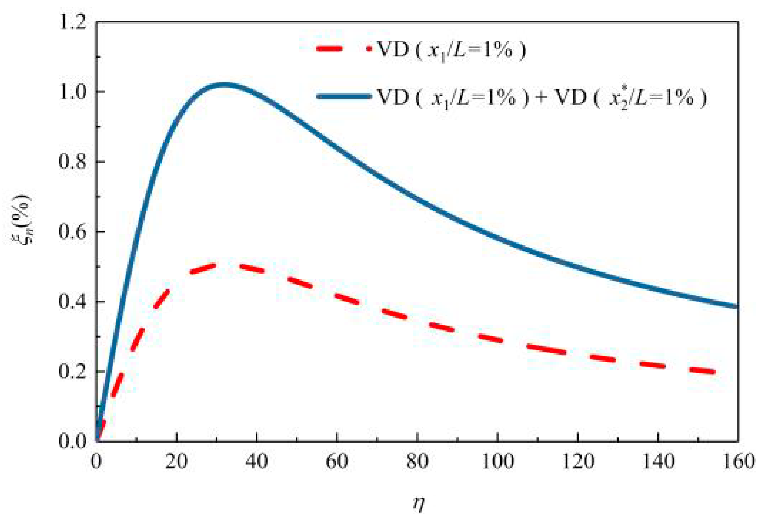
3.5. Parametric Studies

Figure 3 presents the supplemental modal damping ratio of a cable with two symmetric identical VDs versus damping coefficients. For the convenience of comparisons, the results of a cable with a single VD are also shown. It is observed that symmetrically attaching two VDs on the opposite end of a cable is favorable to increasing the maximum supplemental damping ratio of the cable, and its maximum supplemental modal damping ratio is asymptotically the sum of contributions from each VD separately. The findings above are quite consistent with those reported in previous studies [76,77].
Figure 4 presents the supplemental modal damping ratio of a cable with two symmetric identical IMDs or a single IMD versus damping coefficients for various inertial masses. It is clear that two opposite IMDs can provide superior control performance to the cable over a single IMD. Figure 5 directly compares the maximum supplemental modal damping ratio of a cable equipped with a single IMD or two symmetric identical IMDs. For two symmetric identical IMDs with small or medium inertial mass, similarly to the case of two symmetric identical VDs, the maximum achievable supplemental damping ratio is approximately doubled with that provided by a single IMD. It indicates that two opposite IMDs are almost independent from each other. This finding may explain why the optimal damping coefficients of the IMDs for both the single configuration and two-symmetric configuration are similar to each other in magnitude, as shown in Figure 4. Moreover, the maximum achievable supplemental modal damping ratio of a cable provided by two symmetric identical IMDs is larger than that provided by a single IMD or two symmetric identical VDs.

4. Two IMDs at the Same End

4.1. The Wavenumber Equation

When two IMDs are installed at the same end of the cable, substituting Equation (8) into Equation (7) and rearranging terms gives the following expression relating to x 1 and x 2 :
tan β L = A 2 + i B 2 C 2 + i D 2 ,
A 2 = χ 1 sin 2 β x 1 χ 2 sin 2 β x 2 + ( χ 1 χ 2 η 1 η 2 ) sin β x 1 sin β x 2 sin β ( x 2 x 1 ) ,
B 2 = η 1 sin 2 β x 1 + η 2 sin 2 β x 2 ( χ 1 η 2 + χ 2 η 1 ) sin β x 1 sin β x 2 sin β ( x 2 x 1 ) ,
C 2 = 1 χ 1 sin β x 1 cos β x 1 χ 2 sin β x 2 cos β x 2 + ( χ 1 χ 2 η 1 η 2 ) sin β x 1 cos β x 2 sin β ( x 2 x 1 )
D 2 = η 1 sin β x 1 cos β x 1 + η 2 sin β x 2 cos β x 2 ( χ 1 η 2 + χ 2 η 1 ) sin β x 1 cos β x 2 sin β ( x 2 x 1 )

4.2. Asymptotic Solution

Similarly to the case of two opposite IMDs, assuming two IMDs locations x 1 , x 2 L and the wave number β n of the damped cable to be small perturbations from β n 0 , Equation (16) can be simplified as:
β n L n π + β n 0 E 2 + i F 2 G 2 + i H 2 ,
E 2 = b 1 ¯ x 1 b 2 ¯ x 2 + ( b 1 ¯ b 2 ¯ c 1 ¯ c 2 ¯ ) ( x 2 x 1 ) ,
F 2 = c 1 ¯ x 1 + c 2 ¯ x 2 ( b 1 ¯ c 2 ¯ + b 2 ¯ c 1 ¯ ) ( x 2 x 1 ) ,
G 2 = 1 b 1 ¯ b 2 ¯ + ( b 1 ¯ b 2 ¯ c 1 ¯ c 2 ¯ ) ( 1 x 1 / x 2 ) ,
H 2 = c 1 ¯ + c 2 ¯ ( b 1 ¯ c 2 ¯ + b 2 ¯ c 1 ¯ ) ( 1 x 1 / x 2 ) .
From Equations (12) and (17), the asymptotic modal damping ratio of a cable with two IMDs at the same end can be obtained as:
ξ n Im [ Δ β n ] β n 0 = F 2 G 2 E 2 H 2 ( G 2 ) 2 + ( H 2 ) 2 .

4.3. Numerical Solution

Similarly to the case of two opposite IMDs, Equation (16) can be solved for the wavenumber using the fixed-point iteration. Starting from the undamped wavenumber β n 0 , the iterative scheme is given by:
β n k + 1 L = n π + arctan A ¯ 2 + i B ¯ 2 C ¯ 2 + i D ¯ 2 ,
A ¯ 2 = χ 1 sin 2 β n k x 1 χ 2 sin 2 β n k x 2 + ( χ 1 χ 2 η 1 η 2 ) sin β n k x 1 sin β n k x 2 sin β n k ( x 2 x 1 ) ,
B ¯ 2 = η 1 sin 2 β n k x 1 + η 2 sin 2 β n k x 2 ( χ 1 η 2 + χ 2 η 1 ) sin β n k x 1 sin β n k x 2 sin β n k ( x 2 x 1 ) ,
C ¯ 2 = 1 χ 1 sin β n k x 1 cos β n k x 1 χ 2 sin β n k x 2 cos β n k x 2 + ( χ 1 χ 2 η 1 η 2 ) sin β n k x 1 cos β n k x 2 sin β n k ( x 2 x 1 )
D ¯ 2 = η 1 sin β n k x 1 cos β n k x 1 + η 2 sin β n k x 2 cos β n k x 2 ( χ 1 η 2 + χ 2 η 1 ) sin β n k x 1 cos β n k x 2 sin β n k ( x 2 x 1 )
After solving numerically for the wavenumber, the supplemental modal damping ratio of a cable with two IMDs at the same end can be determined from Equation (12).

4.4. Comparison of Asymptotic and Numerical Solutions

Figure 6 shows the comparison of asymptotic and numerical complex wavenumbers of a cable with two IMDs at the same end for various inertial masses, where two IMDs are installed at distances x 1 of 1%L and x 2 of 2%L from the left end of the cable, i.e., x 1 = 1 % L , x 2 = 2 % L . Seeing that two IMDs are usually identical, some simplifications in the notation are introduced, i.e., b 1 = b 2 = b , χ 1 = χ 2 = χ , c 1 = c 2 = c , and η 1 = η 2 = η . Similar to the case of two opposite IMDs, the loci start from the undamped wavenumber along a semicircular contour and finally attach to the real axis when damping coefficients of the IMDs increase from zero to infinity, and the effect of two IMDs installed at the same end of the cable on the cable frequency is also not significant. For a cable with two IMDs at the same end, although the asymptotic complex wavenumber agrees well with the numerical solution when the small inertial mass ( χ 0.3 / ( n π x 2 / L ) ) is used, it will lose accuracy when moderate or large inertial mass ( 0.6 / ( n π x 2 / L ) χ 0.9 / ( n π x 2 / L ) ) is adopted. Compared to the case of two opposite IMDs, prediction accuracies of the asymptotic solution are found to be relatively poor when two IMDs are installed at the same end of the cable. Hence, numerical results are used for the following parametric study.

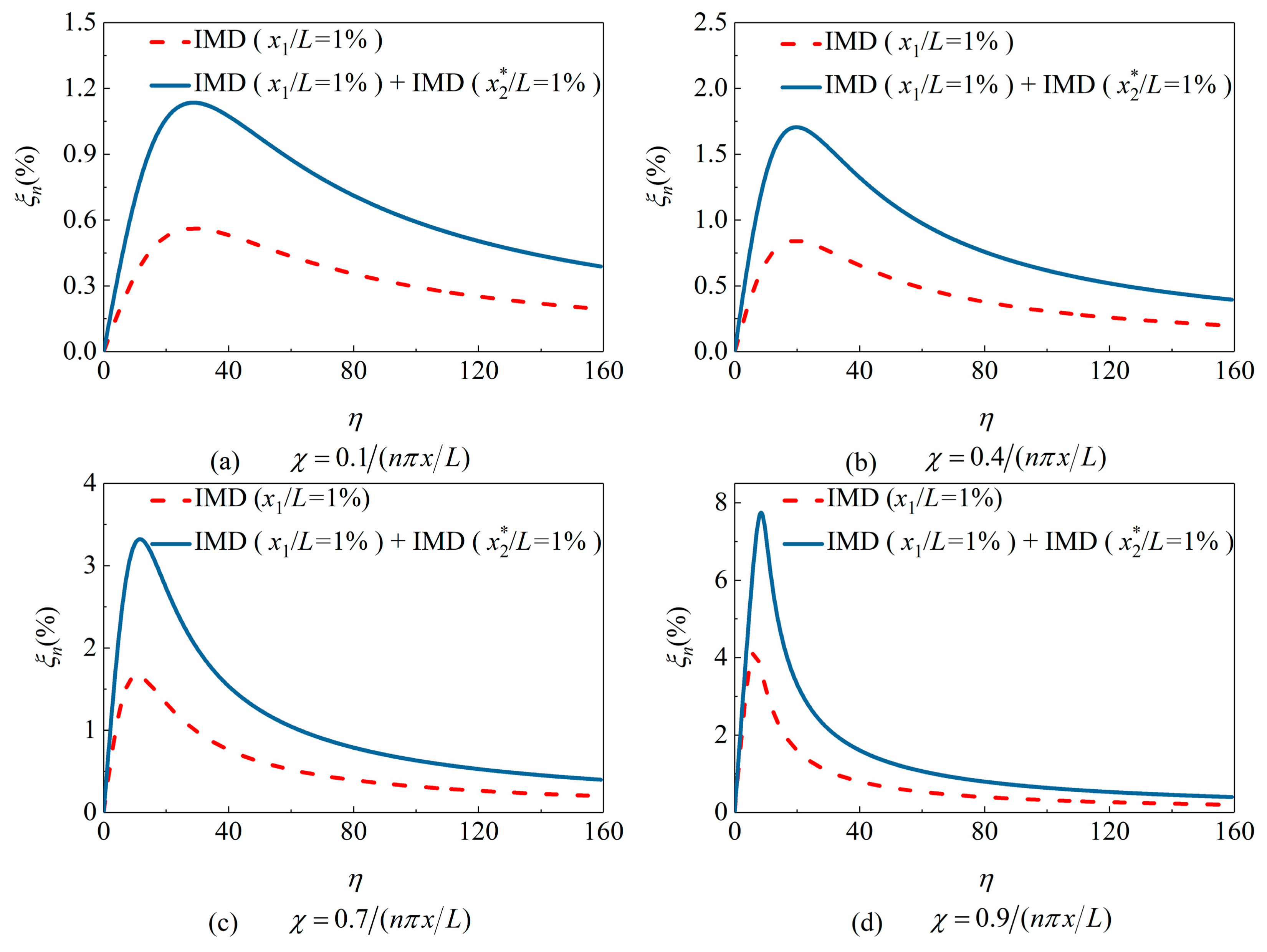
4.5. Parametric Studies

Figure 7 presents the supplemental modal damping ratio of a cable with two identical VDs at the same end or a single VD versus damping coefficients. It is observed that attaching two VDs at the same ends of the cable may help to reduce the damper size but cannot increase the maximum supplemental modal damping ratio. Moreover, its maximum modal damping ratio is slightly smaller than that provided by a single VD at the further distance. These observations are in agreement with previous findings [76,77].
Figure 8 presents the supplemental modal damping ratio of a cable with two identical IMDs at the same end or a single IMD versus damping coefficients of the IMD. If two IMDs with relatively small or big inertial masses ( χ 0.1 / ( n π x 2 / L ) or χ = 0.9 / ( n π x 2 / L ) ) are installed at the same end of the cable, similarly to the case of two VDs at the same end of a cable, there is no advantage of increasing the maximum modal damping ratio over that of a single IMD. However, if moderate inertial mass ( 0.4 / ( n π x 2 / L ) χ 0.7 / ( n π x 2 / L ) ) of the IMD is used, it is interesting to observe that two IMDs at the same end can lead to smaller optimum damping coefficients and larger maximum supplemental modal damping ratios than that of a single IMD at a bigger distance.
The maximum achievable supplemental modal damping ratios of a cable equipped with a single IMD and two IMDs at the same end are directly compared in Figure 9. It is worth noting that the maximum supplemental modal damping ratio provided by two IMDs is higher than the sum of contributions from each IMD when inertial mass χ = 0.7 / ( n π x 2 / L ) is used. Though the strategy of two opposite IMDs has demonstrated that it can provide superior control performance, installing a damper at cable-tower anchorage is difficult and inconvenient. Thus, attaching two IMDs with appropriate inertial mass installed at the same end of the cable seems to be more promising for practical application.

5. Conclusions

In this paper, the combined damping effect of two discrete IMDs on a stay cable, either on the opposite end or the same end, was theoretically investigated in comparison with a single IMD, especially for the single-mode cable vibration control. Results showed that the maximum supplemental modal damping ratio of a cable provided by two opposite IMDs with small or moderate inertial mass is approximately the sum of contributions from each IMD. However, damping performances of the cable with two opposite IMDs will be reduced when the IMDs adopt relatively large inertial mass, in which the superposition effect of each IMD gets weak. As for a cable with two IMDs at the same end, the maximum modal damping ratio of the cable is smaller than that of a single IMD at the further distance when the IMDs adopt relatively small or large inertial mass. Fortunately, when the inertial mass of the IMD is appropriate, attaching two IMDs at the same end of the cable is able to obtain a larger maximum modal damping ratio than that of a single IMD at a bigger distance, which is even more than the sum of contributions from each IMD. Generally, attaching two opposite IMDs on a cable has shown better control performance than two IMDs at the same end. However, installing a damper at cable-tower anchorage is difficult and inconvenient. As an alternative, attaching two IMDs with appropriate inertial mass at the same end of a cable seems to be more promising for practical application. However, it is still necessary to explore the performance of two IMDs for the multimode cable vibration control, especially for super-long cables, which will be our consideration for further study.

Author Contributions

Z.W., F.Y., and H.G. conceived the idea of this research; Z.W. and F.Y. wrote the paper; H.G. reviewed and revised the paper.

Funding

The research was financially supported by the National Natural Science Foundation of China (Grant No. 51878274).

Conflicts of Interest

The authors declare no conflict of interest.

References

  1. Mao, J.X.; Wang, H.; Feng, D.M.; Tao, T.Y.; Zheng, W.Z. Investigation of dynamic properties of long-span cable-stayed bridges based on one-year monitoring data under normal operating condition. Struct. Control Health Monit. 2018, 25, e2146. [Google Scholar] [CrossRef]
  2. Zhou, H.J.; Xu, Y.L. Wind-rain-induced vibration and control of stay cables in a cable-stayed bridge. Struct. Control Health Monit. 2007, 14, 1013–1033. [Google Scholar] [CrossRef]
  3. Wang, Z.H.; Chen, Z.Q.; Gao, H.; Wang, H. Development of a self-powered magnetorheological damper system for cable vibration control. Appl. Sci. 2018, 8, 118. [Google Scholar] [CrossRef]
  4. Kleissl, K.; Georgakis, C.T. Comparison of the aerodynamics of bridge cables with helical fillets and a pattern-indented surface. J. Wind Eng. Ind. Aerod. 2012, 104, 166–175. [Google Scholar] [CrossRef]
  5. He, X.H.; Cai, C.; Wang, Z.J.; Jing, H.Q.; Chen, Z.Q. Experimental verification of the effectiveness of elastic cross cross-ties in suppressing wake wake-induced vibrations of staggered stay cables. Eng. Struct. 2018, 167, 151–165. [Google Scholar] [CrossRef]
  6. Pacheco, B.M.; Fujino, Y.; Sulekh, A. Estimation curve for modal damping in stay cables with viscous damper. J. Struct. Eng. 1993, 119, 1961–1979. [Google Scholar] [CrossRef]
  7. Xu, Y.L.; Zhou, H.J. Damping cable vibration for a cable-stayed bridge using adjustable fluid dampers. J. Sound Vib. 2007, 306, 349–360. [Google Scholar] [CrossRef]
  8. Mekki, O.B.; Auricchio, F. Performance evaluation of shape-memory-alloy superelastic behavior to control a stay cable in cable-stayed bridges. Int. J. Non-Lin. Mech. 2011, 46, 470–477. [Google Scholar] [CrossRef]
  9. Soltane, S.; Montassar, S.; Ben Mekki, O.; El Fatmi, R. A hysteretic Bingham model for MR dampers to control cable vibrations. J. Mech. Mater. Struct. 2015, 10, 195–206. [Google Scholar] [CrossRef]
  10. Miyata, T.; Yamada, H.; Hojo, T. Experimental study on aerodynamic characteristics of cables with patterned surface. J. Struct. Eng. 1994, 40, 1065–1076. [Google Scholar]
  11. Caracoglia, L.; Jones, N.P. In-plane dynamic behavior of cable networks. Part 2: Prototype prediction and validation. J. Sound Vib. 2005, 279, 993–1014. [Google Scholar] [CrossRef]
  12. Krenk, S. Vibration of a taut cable with an external damper. J. Appl. Mech. 2000, 67, 772–776. [Google Scholar] [CrossRef]
  13. Xu, Y.L.; Yu, Z. Vibration of inclined sag cables with oil dampers in cable stayed bridges. J. Bridge Eng. 1998, 3, 194–203. [Google Scholar] [CrossRef]
  14. Krenk, S.; Nielsen, S.R.K. Vibrations of a shallow cable with a viscous damper. Proc. R. Soc. Lond. A 2002, 458, 339–357. [Google Scholar] [CrossRef]
  15. Hoang, N.; Fujino, Y. Analytical study on bending effects in a stay cable with a damper. J. Eng. Mech. 2007, 133, 1241–1246. [Google Scholar] [CrossRef]
  16. Main, J.A.; Jones, N.P. Vibration of tensioned beams with intermediate damper. II: Damper near a support. J. Eng. Mech. 2007, 133, 379–388. [Google Scholar] [CrossRef]
  17. Krenk, S.; Høgsberg, J.R. Damping of cables by a transverse force. J. Eng. Mech. 2005, 131, 340–348. [Google Scholar] [CrossRef]
  18. Huang, Z.; Jones, N.P. Damping of taut-cable systems: Effects of linear elastic spring support. J. Eng. Mech. 2011, 137, 512–518. [Google Scholar] [CrossRef]
  19. Tabatabai, H.; Mehrabi, A.B. Design of mechanical viscous dampers for stay cables. J. Bridge Eng. 2000, 5, 114–123. [Google Scholar] [CrossRef]
  20. Fujino, Y.; Hoang, N. Design formulas for damping of a stay cable with a damper. J. Struct. Eng. 2008, 134, 269–278. [Google Scholar] [CrossRef]
  21. Cheng, S.H.; Darivandi, N.; Ghrib, F. The design of an optimal viscous damper for a bridge stay cable using energy-based approach. J. Sound Vib. 2010, 329, 4689–4704. [Google Scholar] [CrossRef]
  22. Fournier, J.A.; Cheng, S.H. Impact of damper stiffness and damper support stiffness on the efficiency of a linear viscous damper in controlling stay cable vibrations. J. Bridge Eng. 2014, 19, 04013022. [Google Scholar] [CrossRef]
  23. Javanbakht, M.; Cheng, S.H.; Ghrib, F. Control-oriented model for the dynamic response of a damped cable. J. Sound Vib. 2019, 442, 249–267. [Google Scholar] [CrossRef]
  24. Li, H.; Liu, M.; Ou, J.P. Negative stiffness characteristics of active and semi-active control systems for stay cables. Struct. Control Health Monit. 2008, 15, 120–142. [Google Scholar] [CrossRef]
  25. Iemura, H.; Pradono, M.H. Advances in the development of pseudo-negative-stiffness dampers for seismic response control. Struct. Control Health Monit. 2009, 16, 784–799. [Google Scholar] [CrossRef]
  26. Johnson, E.A.; Christenson, R.E.; Spencer, B.F. Semiactive damping of cables with sag. Comput. Aided Civ. Inf. 2003, 18, 132–146. [Google Scholar] [CrossRef]
  27. Duan, Y.F.; Ni, Y.Q.; Ko, J.M. State-derivative feedback control of cable vibration using semiactive magnetorheological dampers. Comput. Aided Civ. Inf. 2005, 20, 431–449. [Google Scholar] [CrossRef]
  28. Duan, Y.F.; Ni, Y.Q.; Zhang, H.M.; Spencer, B.F.; Ko, J.M.; Fang, Y. Design formulas for vibration control of taut cables using passive MR dampers. Smart Struct. Syst. 2019, 23, 521–536. [Google Scholar]
  29. Huang, H.W.; Liu, T.T.; Sun, L.M. Multi-mode cable vibration control using MR damper based on nonlinear modeling. Smart Struct. Syst. 2019, 23, 565–577. [Google Scholar]
  30. Chen, Z.Q.; Wang, X.Y.; Ko, J.M.; Ni, Y.Q.; Spencer, B.F.; Yang, G. MR damping system for mitigating wind-rain induced vibration on Dongting Lake Cable-Stayed Bridge. Wind Struct. 2004, 7, 293–304. [Google Scholar] [CrossRef]
  31. Li, H.; Liu, M.; Li, J.H.; Guan, X.C.; Ou, J.P. Vibration control of stay cables of Shandong Binzhou Yellow River Highway Bridge by using magnetorheological fluid dampers. J. Bridge Eng. 2007, 12, 401–409. [Google Scholar] [CrossRef]
  32. Weber, F.; Distl, H. Amplitude and frequencyindependent cable damping of Sutong Bridge and Russky Bridge by magnetorheological dampers. Struct. Control Health Monit. 2015, 22, 237–254. [Google Scholar] [CrossRef]
  33. Chen, L.; Sun, L.M.; Nagarajaiah, S. Cable with discrete negative stiffness device and viscous damper: Passive realization and general characteristics. Smart Struct. Syst. 2015, 15, 627–643. [Google Scholar] [CrossRef]
  34. Zhou, P.; Li, H. Modeling and control performance of a negative stiffness damper for suppressing stay cable vibrations. Struct. Control Health Monit. 2016, 23, 764–782. [Google Scholar] [CrossRef]
  35. Shi, X.; Zhu, S.Y. Magnetic negative stiffness dampers. Smart Mater. Struct. 2015, 24, 072002. [Google Scholar] [CrossRef]
  36. Shi, X.; Zhu, S.Y.; Li, J.Y.; Spencer, B.F. Dynamic behavior of stay cables with passive negative stiffness dampers. Smart Mater. Struct. 2016, 25, 75044. [Google Scholar] [CrossRef]
  37. Shi, X.; Zhu, S.Y.; Nagarajaiah, S. Performance comparison between passive negative stiffness damper and active control in cable vibration mitigation. J. Bridge Eng. 2017, 22, 04017054. [Google Scholar] [CrossRef]
  38. Shi, X.; Zhu, S.Y.; Spencer, B.F. Experimental study on passive negative stiffness damper for cable vibration mitigation. J. Eng. Mech. 2017, 143, 04017070. [Google Scholar] [CrossRef]
  39. Javanbakht, M.; Cheng, S.H.; Ghrib, F. Refined damper design formula for a cable equipped with a positive or negative stiffness damper. Struct. Control Health. Monit. 2018, 25, e2236. [Google Scholar] [CrossRef]
  40. Smith, M.C. Synthesis of mechanical networks: The inerter. IEEE Ttans. Automat. Control 2002, 47, 1648–1662. [Google Scholar] [CrossRef]
  41. Ikago, K.; Saito, K.; Inoue, N. Seismic control of single-degree-of-freedom structure using tuned viscous mass damper. Earthq. Eng. Struct. Dyn. 2012, 41, 453–474. [Google Scholar] [CrossRef]
  42. Takewaki, I.; Murakami, S.; Yoshitomi, S.; Tsuji, M. Fundamental mechanism of earthquake response reduction in building structures with inertial dampers. Struct. Control Health Monit. 2012, 19, 590–608. [Google Scholar] [CrossRef]
  43. Lazar, I.F.; Neild, S.A.; Wagg, D.J. Using an inerter-based device for structural vibration suppression. Earthq. Eng. Struct. Dyn. 2014, 43, 1129–1147. [Google Scholar] [CrossRef]
  44. Nakamura, Y.; Fukukita, A.; Tamura, K.; Matsuoka, T.; Hiramoto, K.; Sunakoda, K. Seismic response control using electro-magnetic inertial mass damper. Earthq. Eng. Struct. Dyn. 2014, 43, 507–527. [Google Scholar] [CrossRef]
  45. Makris, N.; Kampas, G. Seismic protection of structures with supplemental rotational inertia. J. Eng. Mech. 2016, 142, 04016089. [Google Scholar] [CrossRef]
  46. De Domenico, D.; Ricciardi, G. An enhanced base isolation system equipped with optimal tuned mass damper inerter (TMDI). Earthq. Eng. Struct. Dyn. 2018, 47, 1169–1192. [Google Scholar] [CrossRef]
  47. De Domenico, D.; Deastra, P.; Ricciardi, G.; Sims, N.D.; Wagg, D.J. Novel fluid inerter based tuned mass dampers for optimised structural control of base-isolated buildings. J. Frankl. Inst. 2019, 356, 7626–7649. [Google Scholar] [CrossRef]
  48. De Domenico, D.; Ricciardi, G. Improving the dynamic performance of base-isolated structures via tuned mass damper and inerter devices: A comparative study. Struct. Control Health Monit. 2018, 25, e2234. [Google Scholar] [CrossRef]
  49. De Domenico, D.; Ricciardi, G. Optimal design and seismic performance of tuned mass damper inerter (TMDI) for structures with nonlinear base isolation systems. Earthq. Eng. Struct. Dyn. 2018, 47, 2539–2560. [Google Scholar]
  50. Javidialesaadi, A.; Wierschem, N.E. Three-element vibration absorber–inerter for passive control of single-degree-of-freedom structures. J. Vib. Acoust. 2018, 140, 061007. [Google Scholar] [CrossRef]
  51. Pan, C.; Zhang, R.F. Design of structure with inerter system based on stochastic response mitigation ratio. Struct. Control Health Monit. 2018, 25, e2169. [Google Scholar] [CrossRef]
  52. Xu, K.; Bi, K.M.; Han, Q.; Li, X.P.; Du, X.L. Using tuned mass damper inerter to mitigate vortex-induced vibration of long-span bridges: Analytical study. Eng. Struct. 2019, 182, 101–111. [Google Scholar] [CrossRef]
  53. Huang, Z.W.; Hua, X.G.; Chen, Z.Q.; Niu, H.W. Performance evaluation of inerter-based damping devices for structural vibration control of stay cables. Smart Struct. Syst. 2019, 23, 615–626. [Google Scholar]
  54. Luo, J.; Macdonald, J.H.; Jiang, J.Z. Identification of optimum cable vibration absorbers using fixed-sized-inerter layouts. Mech. Mach. Theory 2019, 140, 292–304. [Google Scholar] [CrossRef]
  55. Luo, J.N.; Jiang, J.Z.; Macdonald, J.H.G. Cable vibration suppression with inerter-based absorbers. J. Eng. Mech. 2019, 145, 04018134. [Google Scholar] [CrossRef]
  56. Sun, H.X.; Zuo, L.; Wang, X.Y.; Peng, J.; Wang, W.X. Exact H2 optimal solutions to inerter-based isolation systems for building structures. Struct. Control Health Monit. 2019, 26, e2357. [Google Scholar] [CrossRef]
  57. Wang, Z.H.; Gao, H.; Wang, H.; Chen, Z.Q. Development of stiffness-adjustable tuned mass dampers for frequency retuning. Adv. Struct. Eng. 2019, 22, 473–485. [Google Scholar] [CrossRef]
  58. Zhang, R.F.; Zhao, Z.P.; Dai, K.S. Seismic response mitigation of a wind turbine tower using a tuned parallel inerter mass system. Eng. Struct. 2019, 180, 29–39. [Google Scholar] [CrossRef]
  59. Zhu, H.P.; Li, Y.M.; Shen, W.A.; Zhu, S.Y. Mechanical and energy-harvesting model for electro-magnetic inertial mass dampers. Mech. Syst. Signal Process. 2019, 120, 203–220. [Google Scholar] [CrossRef]
  60. Lu, L.; Duan, Y.F.; Spencer, B.F.; Lu, X.L.; Zhou, Y. Inertial mass damper for mitigating cable vibration. Struct. Control Health Monit. 2017, 24, e1986. [Google Scholar] [CrossRef]
  61. Cu, V.H.; Han, B.; Pham, D.H.; Yan, W.T. Free vibration and damping of a taut cable with an attached viscous mass damper. KSCE J. Civ. Eng. 2018, 22, 1792–1802. [Google Scholar] [CrossRef]
  62. Shi, X.; Zhu, S.Y. Dynamic characteristics of stay cables with inerter dampers. J. Sound Vib. 2018, 423, 287–305. [Google Scholar] [CrossRef]
  63. Wang, Z.H.; Gao, H.; Xu, Y.W.; Chen, Z.Q.; Wang, H. Impact of cable sag on the efficiency of inertial mass damper in controlling stay cable vibrations. Smart Struct. Syst. 2019, 24, 83–94. [Google Scholar]
  64. Wang, Z.H.; Yue, F.F.; Wang, H.; Gao, H.; Fan, B.Q. Refined study on free vibration of a cable with an inertial mass damper. Appl. Sci. 2019, 9, 2271. [Google Scholar] [CrossRef]
  65. Wang, Z.H.; Xu, Y.W.; Gao, H.; Chen, Z.Q.; Xu, K.; Zhao, S.B. Vibration control of a stay cable with a rotary electromagnetic inertial mass damper. Smart Struct. Syst. 2019, 23, 627–639. [Google Scholar]
  66. Lazar, I.F.; Neild, S.A.; Wagg, D.J. Vibration suppression of cables using tuned inerter dampers. Eng. Struct. 2016, 122, 62–71. [Google Scholar] [CrossRef] [Green Version]
  67. Sun, L.M.; Hong, D.X.; Chen, L. Cables interconnected with tuned inerter damper for vibration mitigation. Eng. Struct. 2017, 151, 57–67. [Google Scholar] [CrossRef]
  68. Caracoglia, L.; Jones, N.P. Passive hybrid technique for the vibration mitigation of systems of interconnected stays. J. Sound Vib. 2007, 307, 849–864. [Google Scholar] [CrossRef]
  69. Caracoglia, L.; Zuo, D. Effectiveness of cable networks of various configurations in suppressing stay-cable vibration. Eng. Struct. 2009, 31, 2851–2864. [Google Scholar] [CrossRef]
  70. Zhou, H.J.; Sun, L.M.; Xing, F. Free vibration of taut cable with a damper and a spring. Struct. Control Health Monit. 2014, 21, 996–1014. [Google Scholar] [CrossRef]
  71. Zhou, H.J.; Yang, X.; Sun, L.M.; Xing, F. Free vibrations of a two-cable network with near-support dampers and a cross-link. Struct. Control Health Monit. 2015, 22, 1173–1192. [Google Scholar] [CrossRef]
  72. Ahmad, J.; Cheng, S.; Ghrib, F. Efficiency of an external damper in two-cable hybrid systems. J. Bridge Eng. 2017, 23, 04017138. [Google Scholar] [CrossRef]
  73. Ahmad, J.; Cheng, S.H.; Ghrib, F. Combined effect of external damper and cross-tie on the modal response of hybrid two-cable networks. J. Sound Vib. 2018, 417, 132–148. [Google Scholar] [CrossRef]
  74. Cu, V.H.; Han, B. A stay cable with viscous damper and tuned mass damper. Aust. J. Struct. Eng. 2015, 16, 316–323. [Google Scholar] [CrossRef]
  75. Xu, Y.L.; Yu, Z. Mitigation of three-dimensional vibration of inclined sag cable using discrete oil dampers—II. Application. J. Sound Vib. 1998, 214, 675–693. [Google Scholar] [CrossRef]
  76. Caracoglia, L.; Jones, N.P. Damping of taut-cable systems: Two dampers on a single stay. J. Eng. Mech. 2007, 133, 1050–1060. [Google Scholar] [CrossRef]
  77. Hoang, N.; Fujino, Y. Combined damping effect of two dampers on a stay cable. J. Bridge Eng. 2008, 13, 299–303. [Google Scholar] [CrossRef]
Figure 1. The taut cable with two discrete inertial mass dampers.
Applsci 09 03919 g001
Figure 2. Comparison of asymptotic and numerical complex wavenumbers of a cable with two symmetric identical inertial mass dampers (IMDs) ( x = x 1 = x 2 * = 1 % L ).
Applsci 09 03919 g002
Figure 3. The supplemental modal damping ratio curve of a cable with a single viscous damper (VD) or two symmetric identical VDs ( x = x 1 = x 2 * = 1 % L ).
Applsci 09 03919 g003
Figure 4. The supplemental modal damping ratio curve of a cable with a single IMD or two symmetric identical IMDs ( x = x 1 = x 2 * = 1 % L ).
Applsci 09 03919 g004
Figure 5. The maximum achievable supplemental modal damping ratio of a cable equipped with a single IMD or two symmetric identical IMDs ( x = x 1 = x 2 * = 1 % L ).
Applsci 09 03919 g005
Figure 6. Comparison of asymptotic and numerical complex wavenumbers of a cable with two identical IMDs at the same end ( x 1 = 1 % L , x 2 = 2 % L ).
Applsci 09 03919 g006
Figure 7. The modal damping ratios curves of a cable equipped with a single VD or two identical VDs at the same end ( x 1 = 1 % L , x 2 = 2 % L ).
Applsci 09 03919 g007
Figure 8. The modal damping ratios curves of a cable equipped with a single IMD or two identical IMDs at the same end ( x 1 = 1 % L , x 2 = 2 % L ).
Applsci 09 03919 g008
Figure 9. The maximum achievable supplemental modal damping ratio of a cable equipped with a single IMD or two identical IMDs at the same end ( x 1 = 1 % L , x 2 = 2 % L ).
Applsci 09 03919 g009

