Dome Roof Fall Geohazards of Full-Seam Chamber with Ultra-Large Section in Coal Mine


Abstract
:Featured Application
Abstract
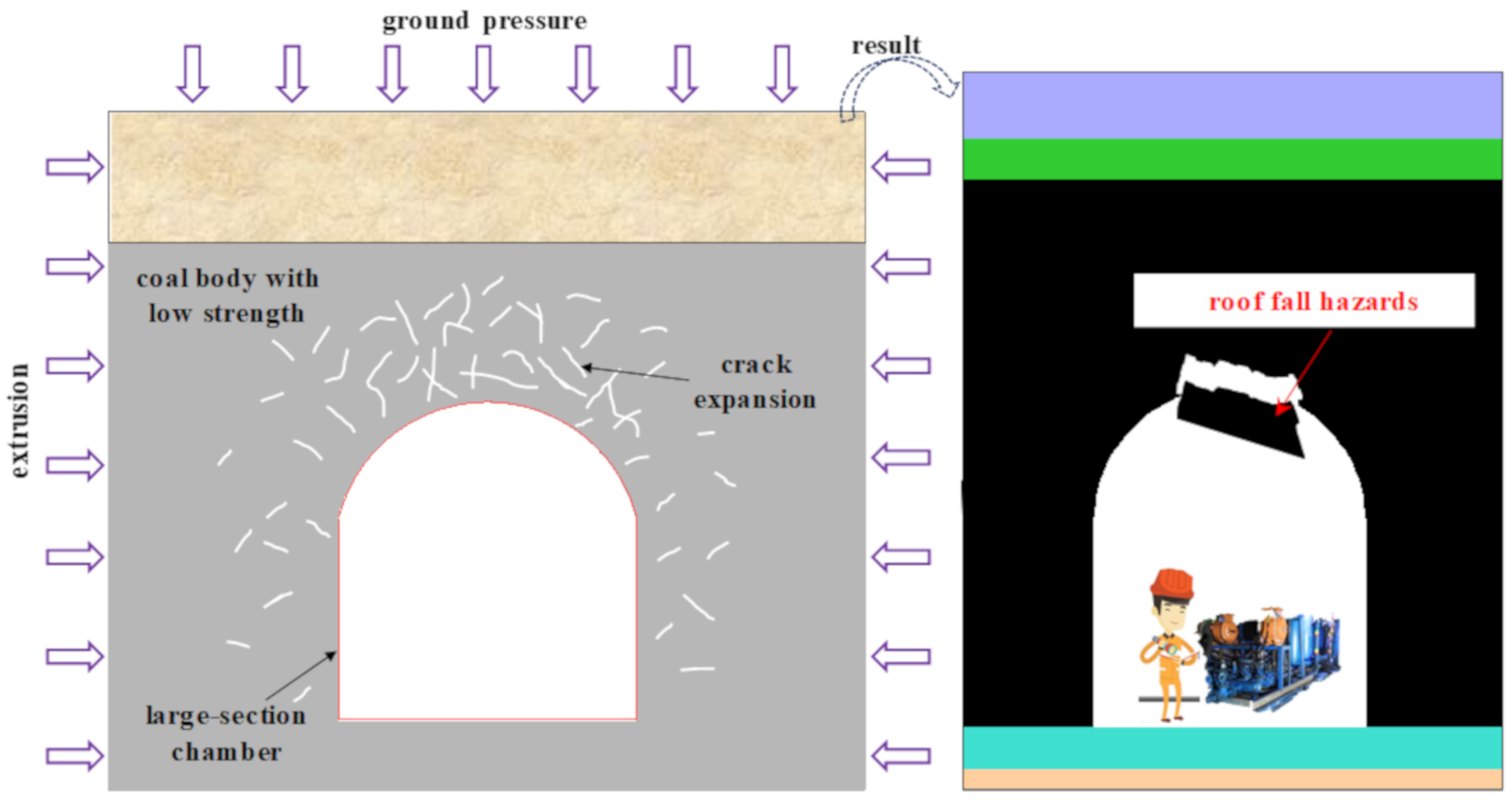
1. Introduction
2. Engineering Background
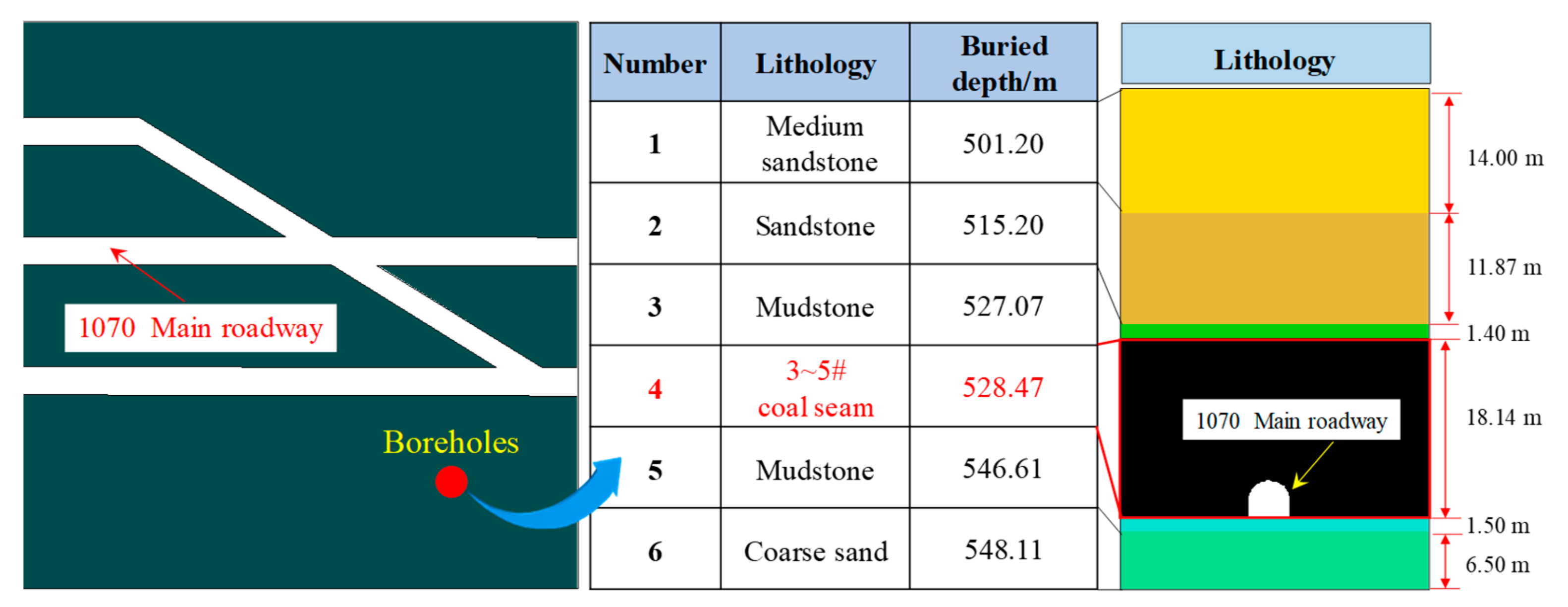
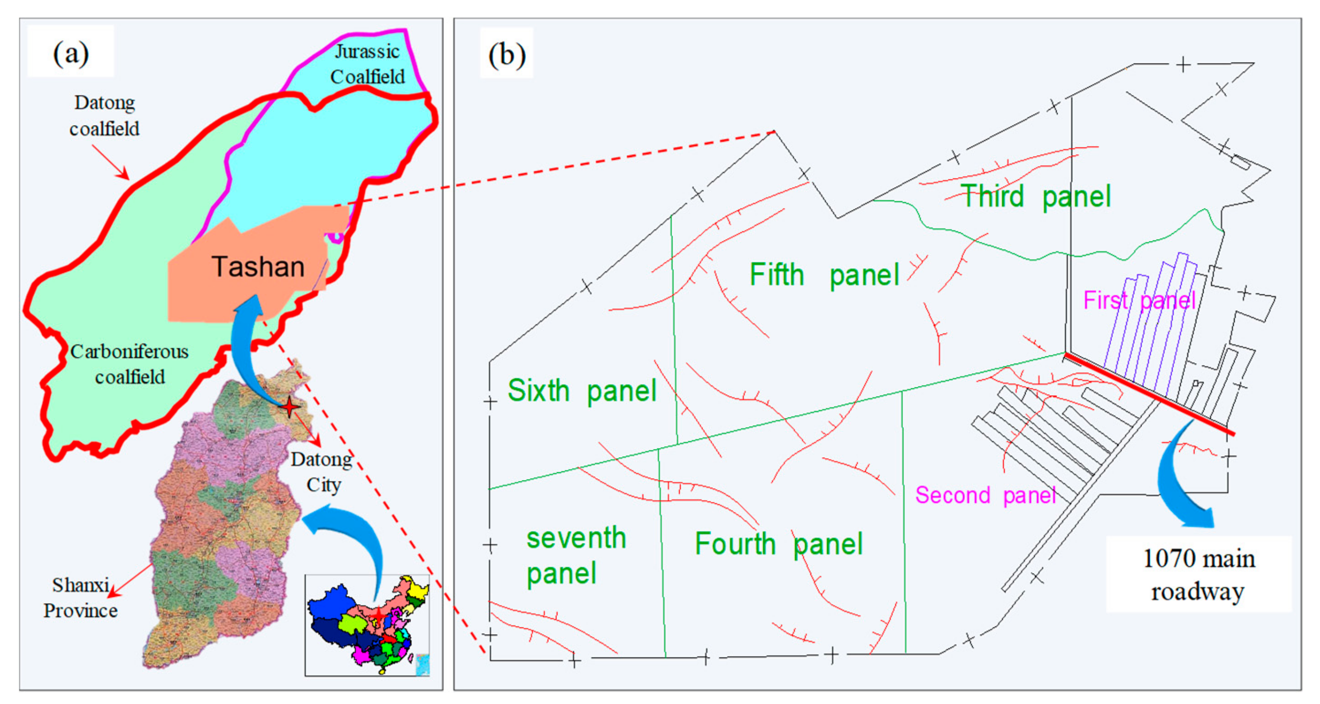
2.1. Geological Conditions
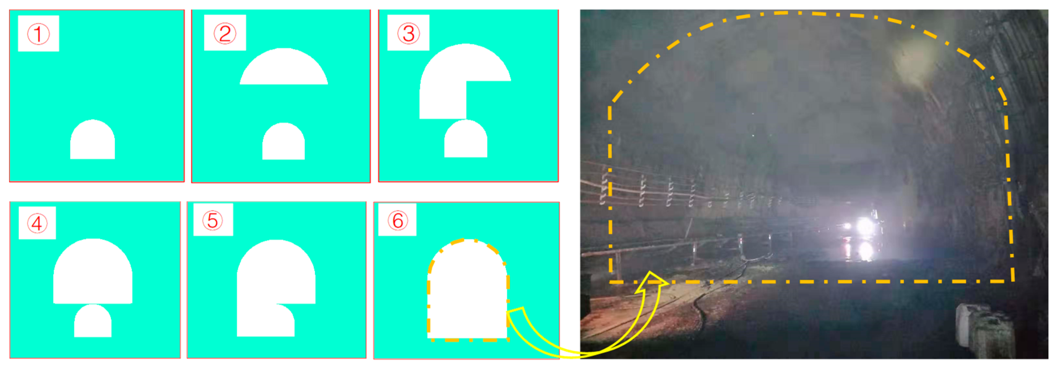
2.2. Chamber Excavation Plan
3. Numerical Model
3.1. Stope Rock Mass Strength
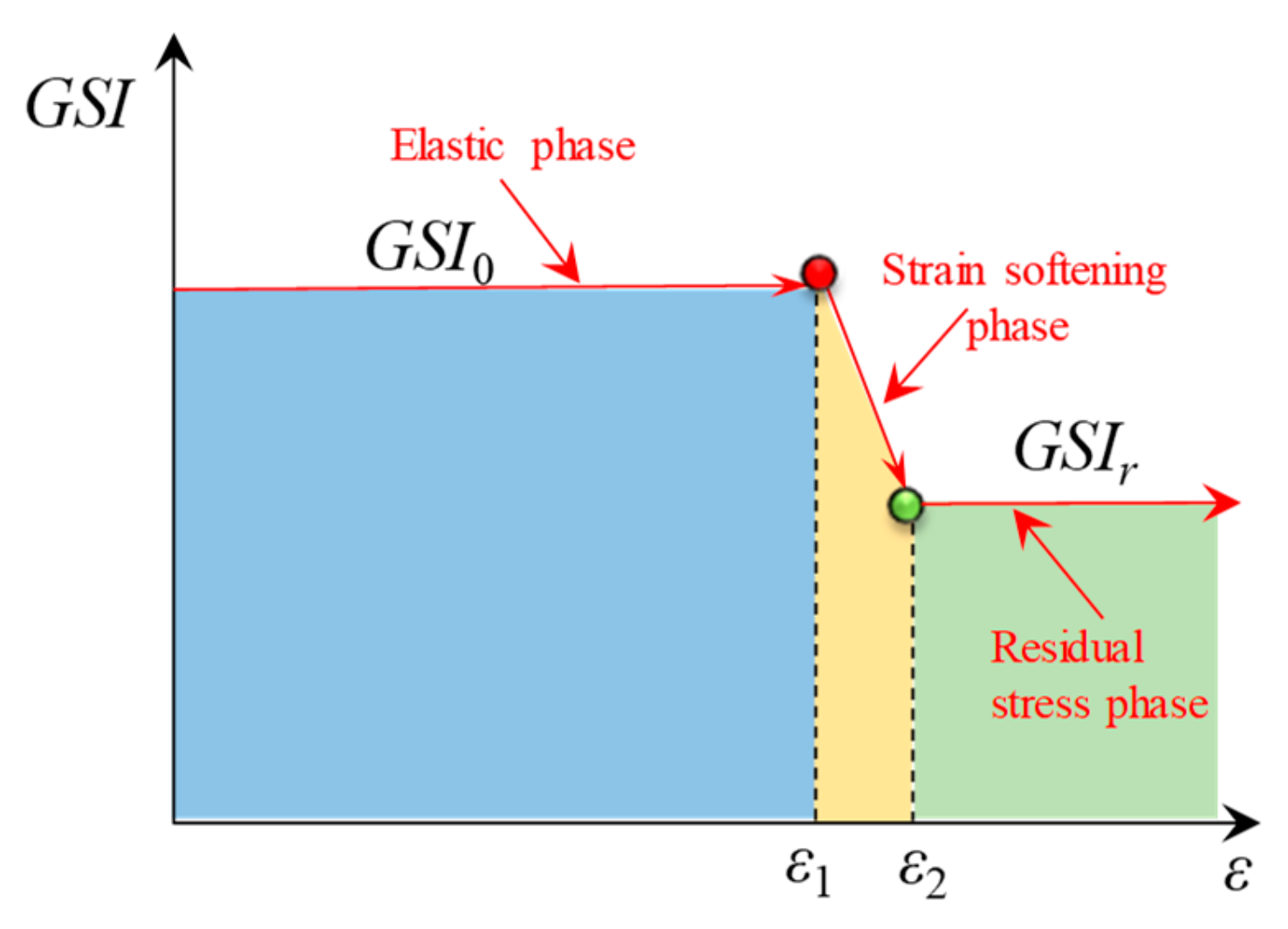
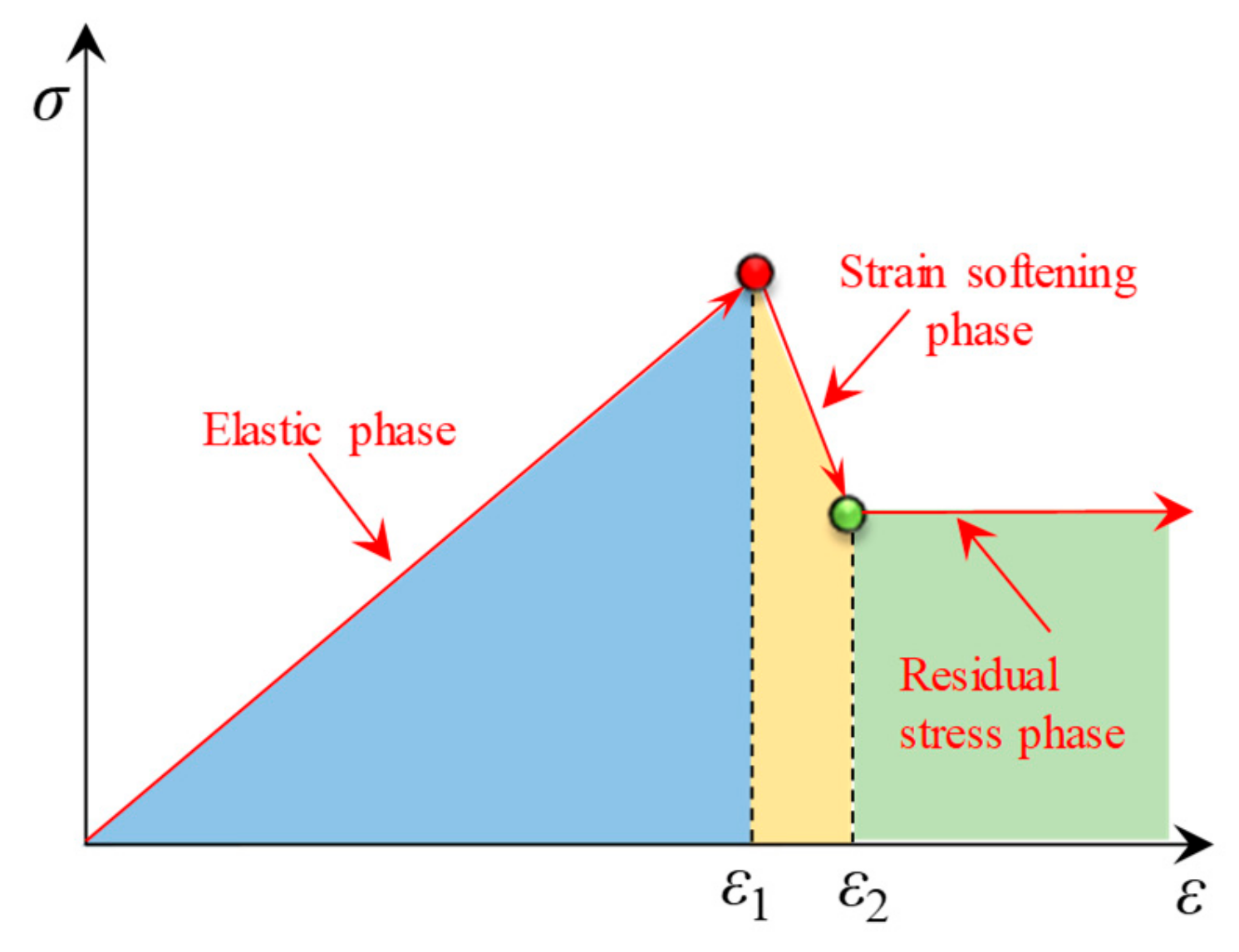
3.2. Hoek-Brown Strain Softening Model
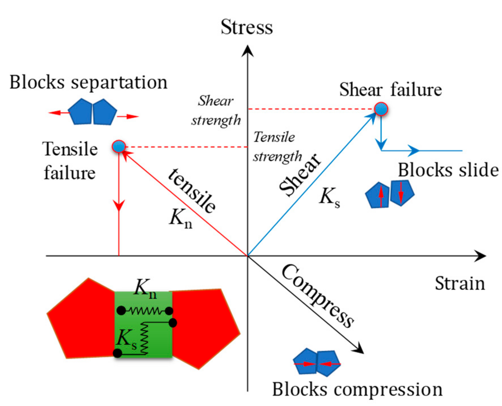
3.3. Fracture Slip and Open Model
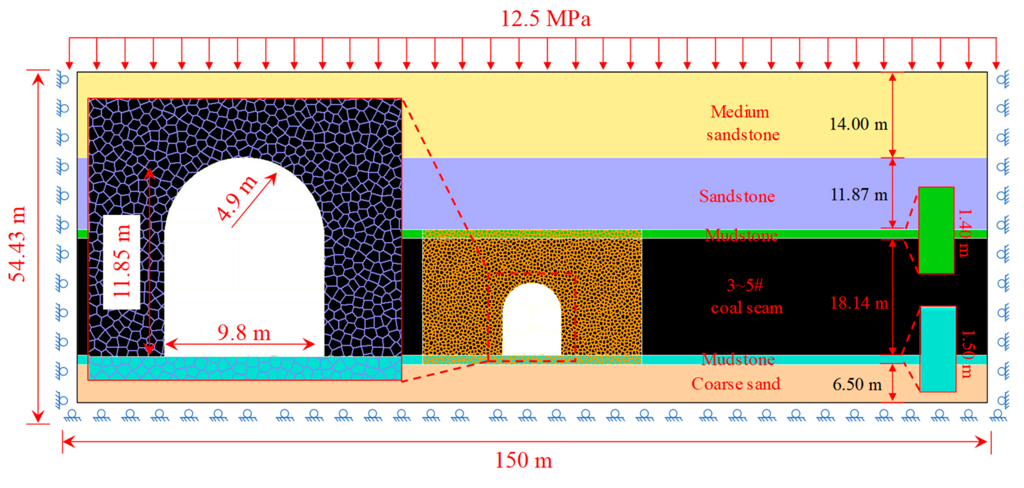
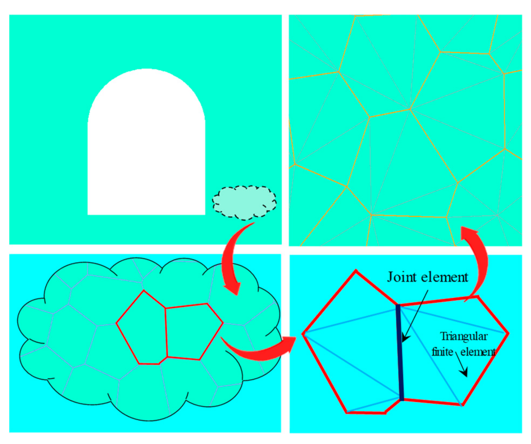
3.4. Model Establishment
3.5. Model Verification
4. Dome Roof fall Mechanism
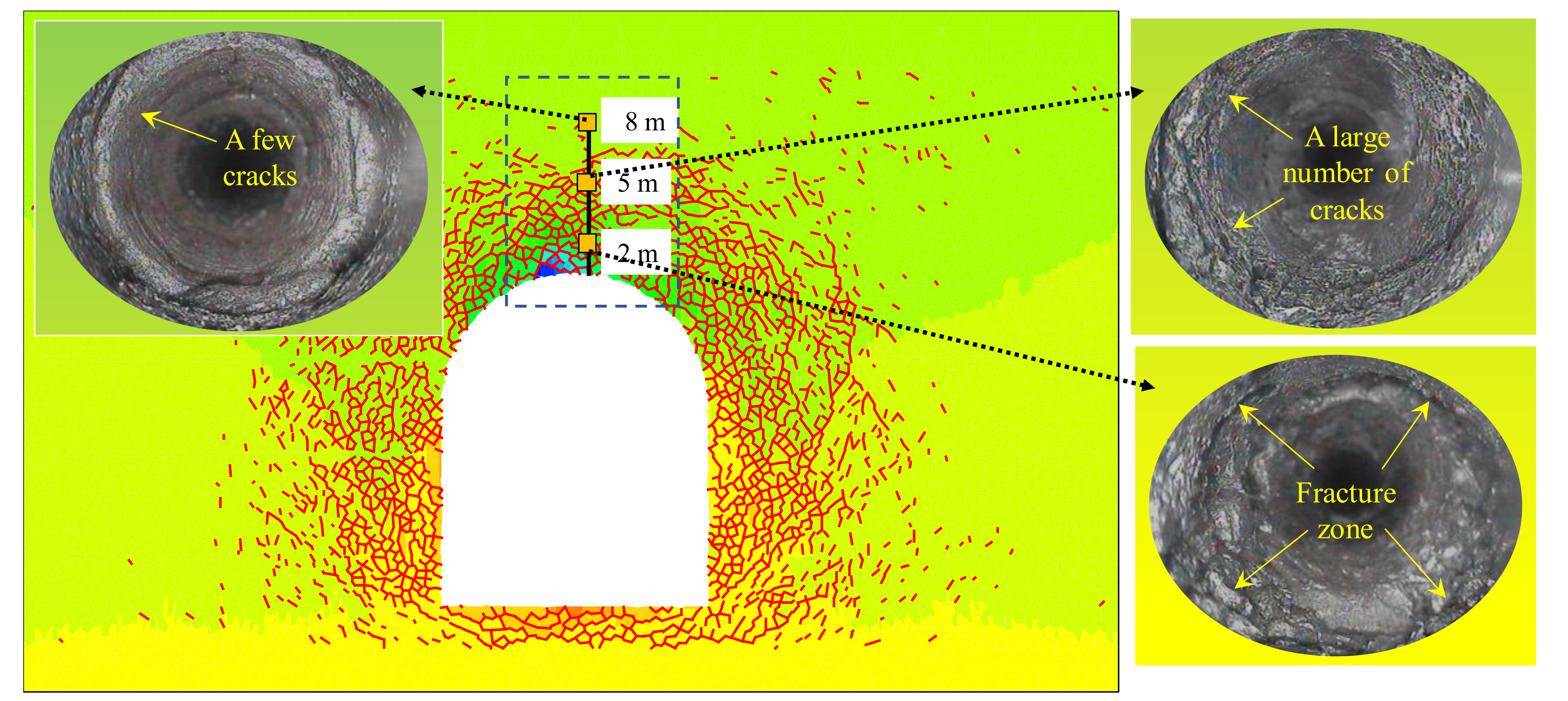
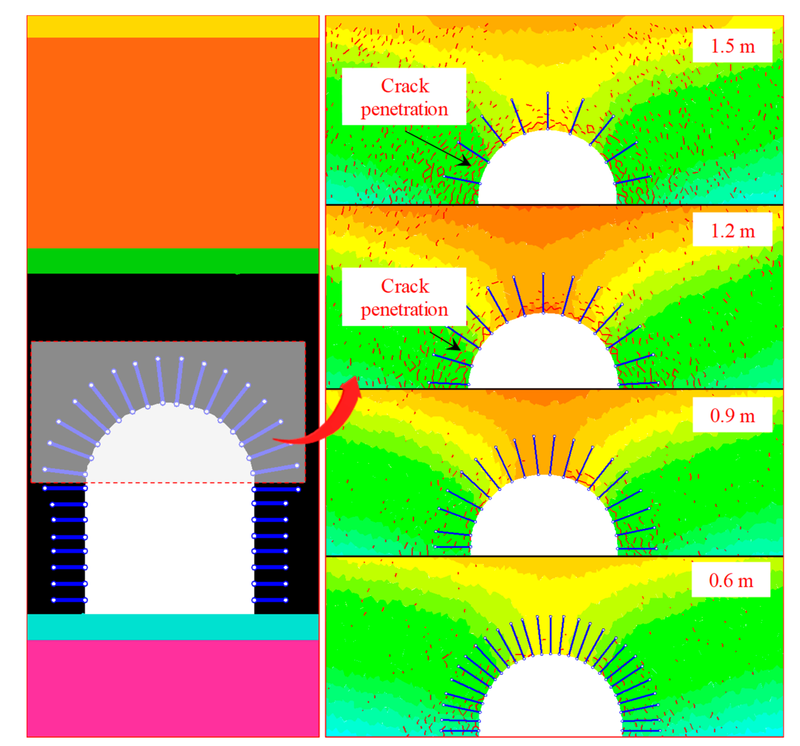
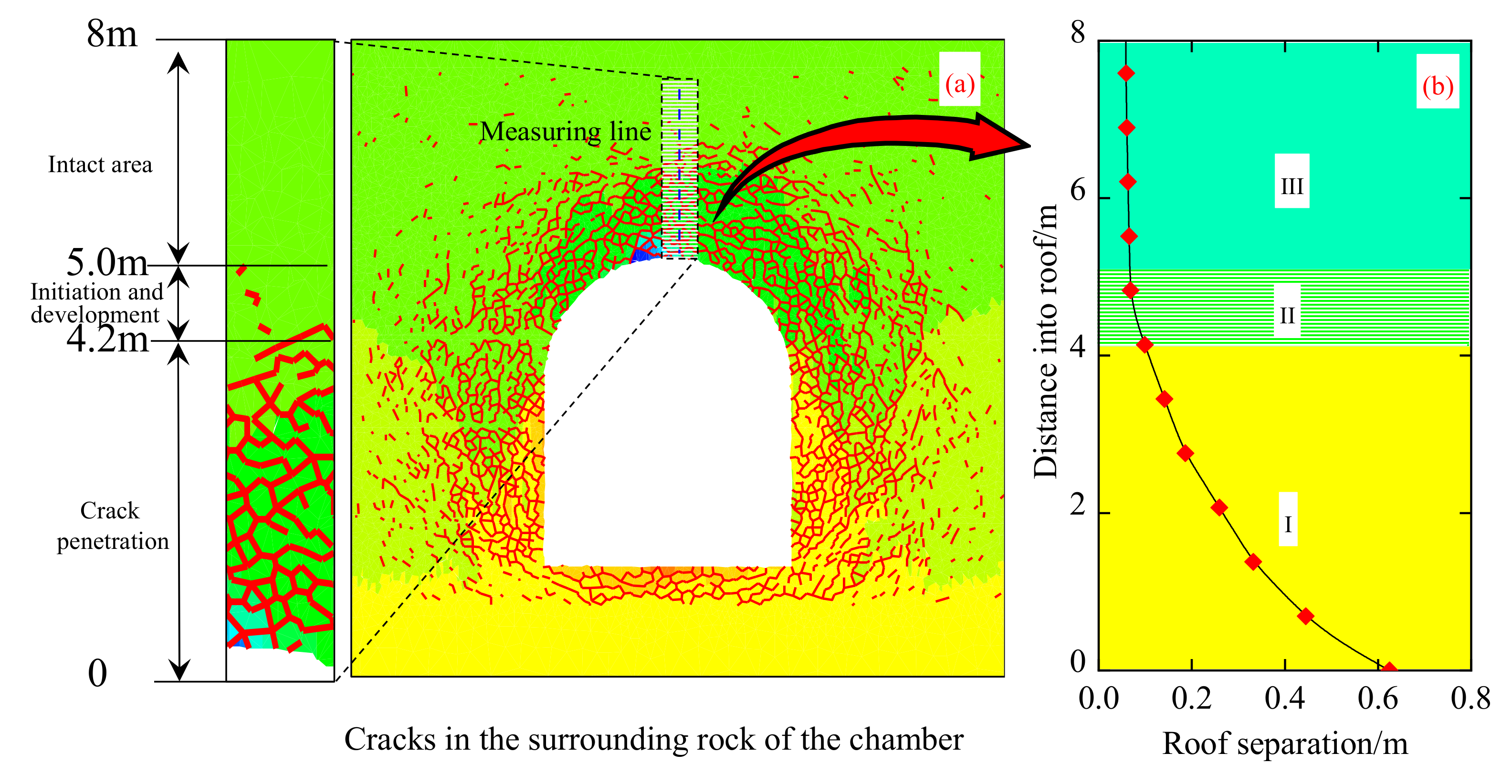
4.1. Relationship Between Separation and the Crack Development
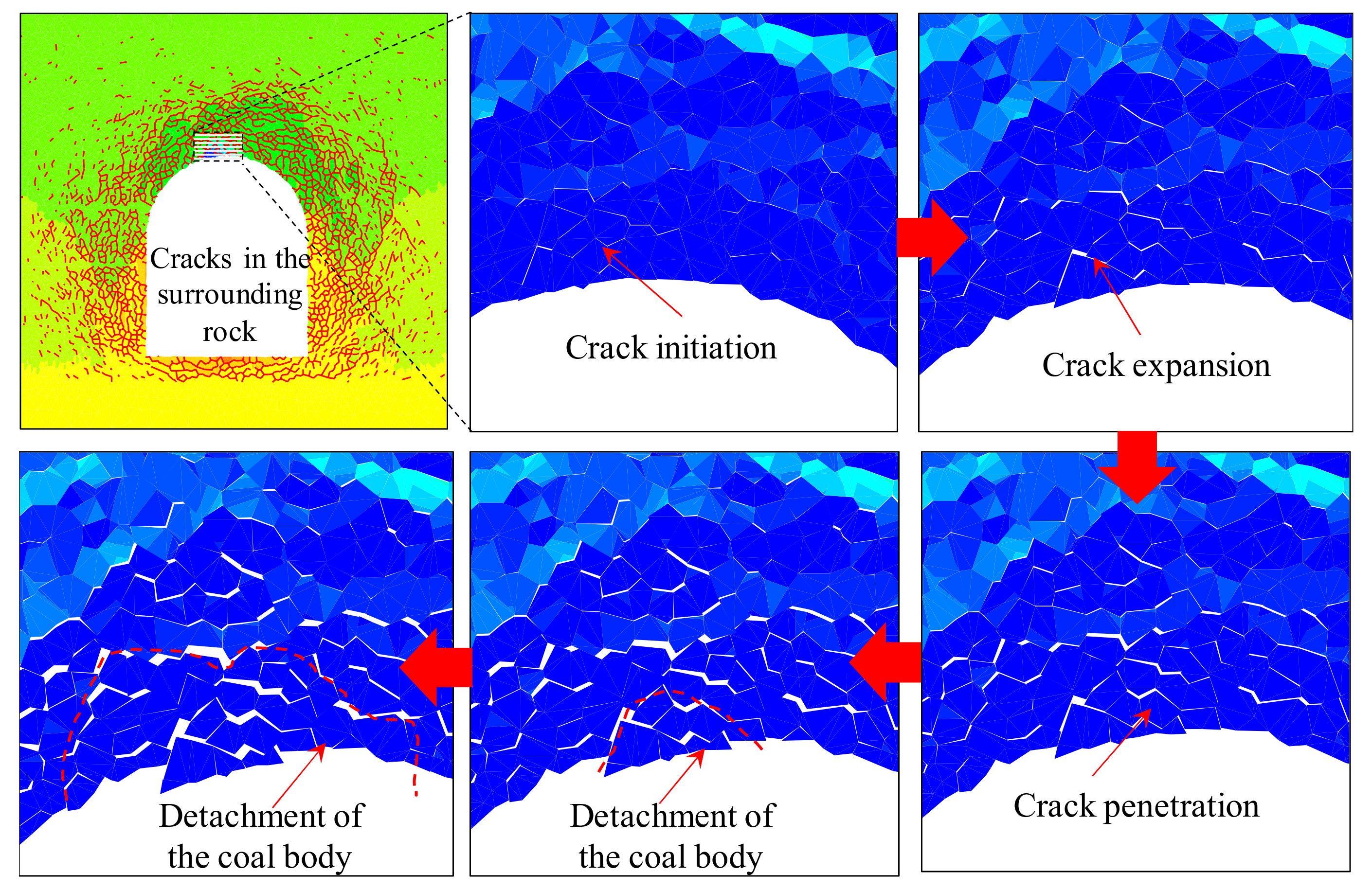
4.2. Roof fall Mechanism of the Chamber
5. Control Technology of Roof Fall
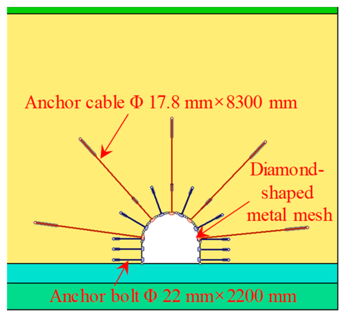
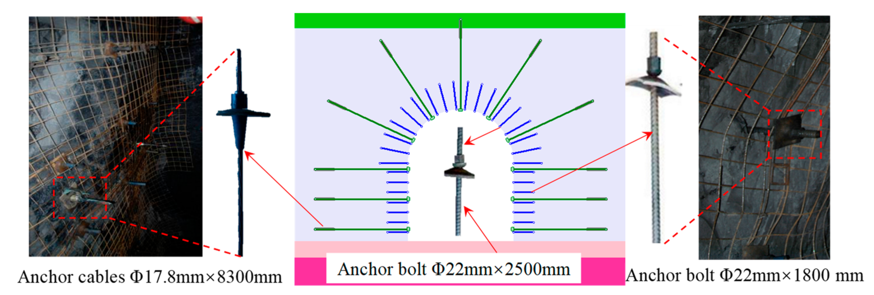
5.1. Parameters of Anchor Bolt and Cable
5.2. Grouting Reinforcement Technology
5.2.1. Grouting Fluid Permeation Diffusion Equation
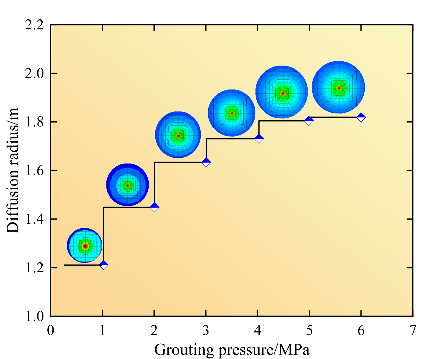
5.2.2. Grouting Slurry Permeation and Diffusion Law
5.3. Chamber Dome Control Effect
6. Engineering Application
6.1. Chamber Support Scheme
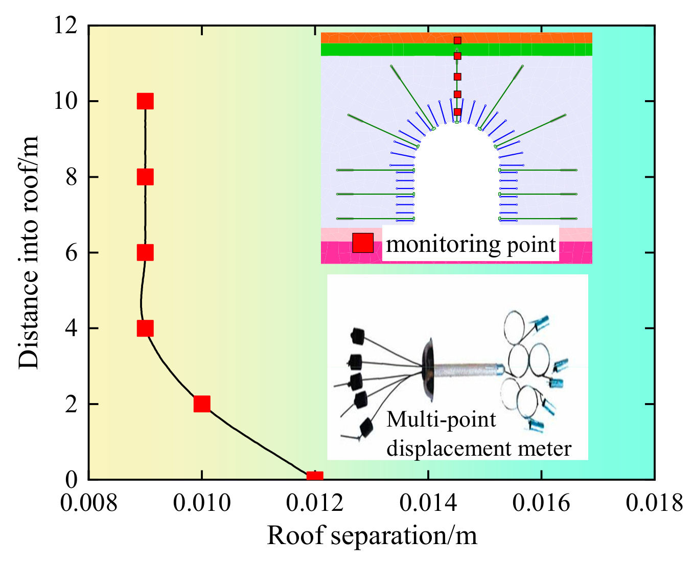
6.2. Chamber Deformation Measurement
7. Conclusions
- (1)
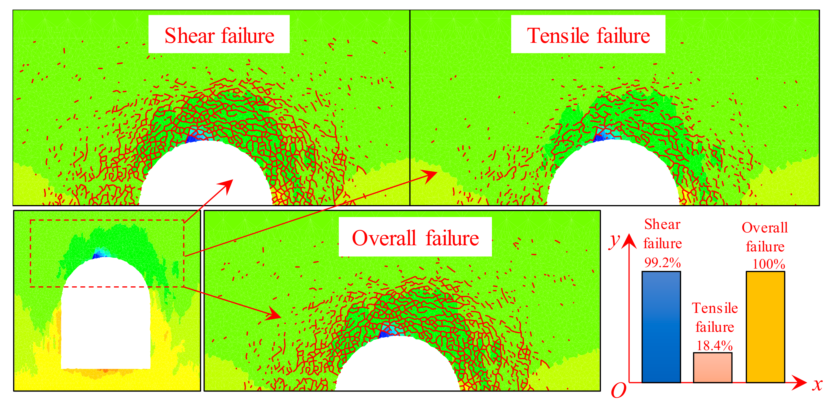
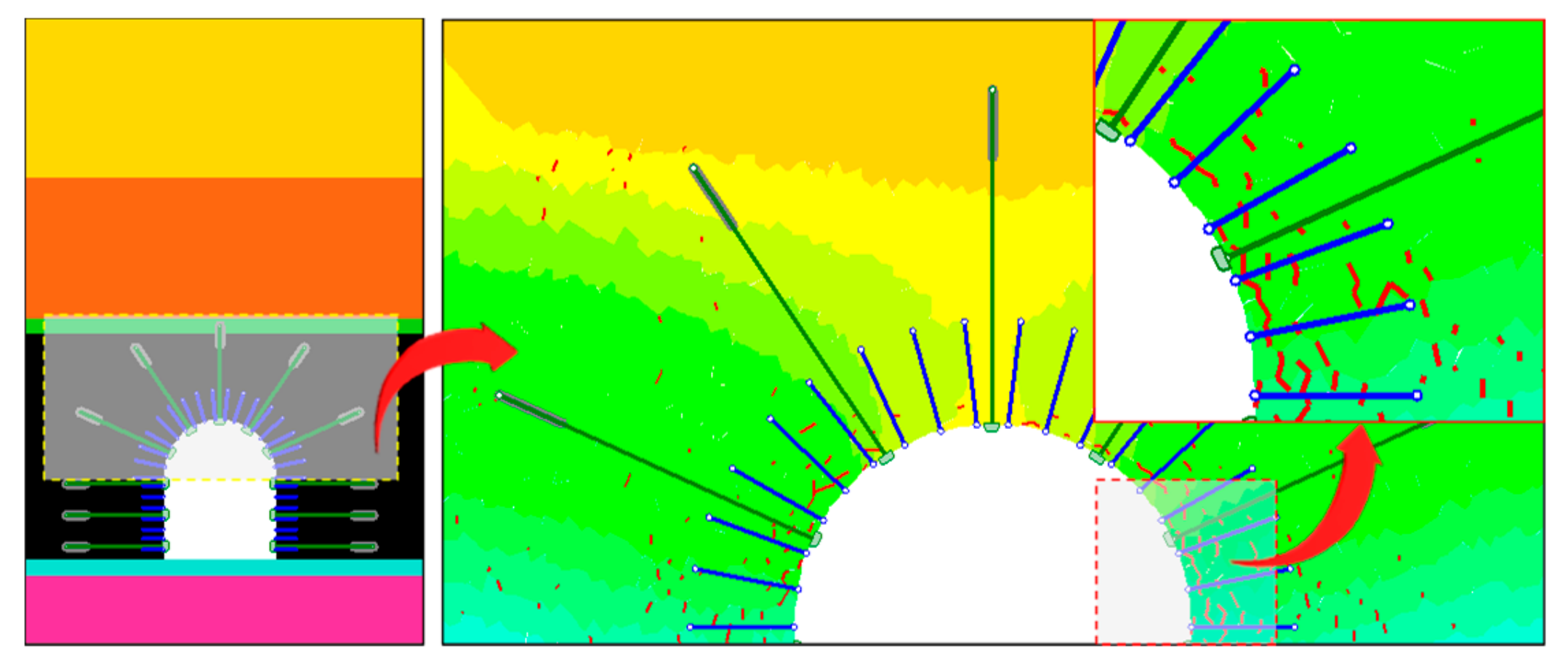
- After excavation, the chamber dome suffers from shear failure, and forming a large number of cracks. In the crack penetration area, the bearing capacity of the chamber dome is significantly reduced and the roof separation is sharply increased. In the crack penetration area, when the crack is connected with the chamber surface, under the effect of the ground pressure, the coal body is separated from the chamber dome and roof fall hazard occurs.
- (2)
- According to the roof fall mechanism of the chamber dome, it was concluded that improving the shear strength of surrounding rock and reducing the penetration of cracks are the main ways to control the roof fall hazard. With the concepts, the pre-tightening force, spacing and length of the anchor bolt and cable, grouting pressure and diffusion radius of the grouting slurry were optimized.
- (3)
- The optimized parameters of anchor bolt, anchor cable and grouting were applied to the strap joint chamber of Tashan Coal Mine. The maximum roof separation of chamber dome is only 0.012 m. The surrounding rock control effect is great, and no roof fall occurs.
Author Contributions
Funding
Acknowledgments
Conflicts of Interest
References
- Leng, X.J.; Li, E.Q.; Liu, J.W.; Li, W.G. The Basic Problems about Fully-Mechanized Top-Coal Caving System. In Applied Mechanics and Materials; Trans Tech Publications: Stafa-Zurich, Switzerland, 2013; pp. 256–259. [Google Scholar]
- Zhao, Y.; Chen, C. Analysis of Guiding Gas Outburst by Roof Fall and Top coal Caving; Coal Industry Publishing House: Beijing, China, 2008. [Google Scholar]
- Duncan, G.; Sobey, G.; Clarke, T. Top coal caving longwall maximizes thick seam recovery - Austar’s longwall system offers opportunities in seams thicker than 4.5 meters. Eng. Min. J. 2007, 208, 50–56. [Google Scholar]
- Fu, Q.; Wu, J. DEM Study of the Drawing Law in Longwall Top-Coal Caving Mining, Computer Applications in the Minerals Industries; Balkema: Leiden, The Netherlands, 2001; pp. 283–286. [Google Scholar]
- Li, Z.H.; Hua, X.Z.; Zhu, R.J.; Zhou, D.S. Numerical Simulation of Strata Behavior in Super-Long and Large Mining Height Working Face. Adv. Mater. Res. 2013, 634, 3428–3432. [Google Scholar] [CrossRef]
- Şimşir, F.; Ozfirat, M.K. Determination of the most effective longwall equipment combination in longwall top coal caving (LTCC) method by simulation modelling. Int. J. Rock Mech. Min. Sci. 2008, 45, 1015–1023. [Google Scholar] [CrossRef]
- Yang, S.Q.; Chen, M.; Jing, H.W.; Chen, K.F.; Meng, B. A case study on large deformation failure mechanism of deep soft rock roadway in Xin’An coal mine, China. Eng. Geol. 2016, 217, 89–101. [Google Scholar] [CrossRef]
- Zhu, Y.P.; Song, X.R. Stress Analysis about Flat Ratio and Surrounding Rock of Large Section Highway Tunnel. Appl. Mech. Mater. 2013, 368, 1404–1409. [Google Scholar] [CrossRef]
- Lu, G.L.; Wang, C.; Jiang, Y.D.; Wang, H.W. Roadway Supporting Technology in Fully Mechanized Workface with Large Mining Height of Specially Thick Coal Seam in Datong Mining Area. Appl. Mech. Mater. 2012, 204, 1611–1616. [Google Scholar] [CrossRef]
- Kang, H.; Lin, J.; Fan, M. Investigation on support pattern of a coal mine roadway within soft rocks—A case study. Int. J. Coal Geol. 2015, 140, 31–40. [Google Scholar] [CrossRef]
- Yan, H.; He, F.L.; Yang, T.; Li, L.Y.; Zhang, S.B.; Zhang, J.X. The mechanism of bedding separation in roof strata overlying a roadway within a thick coal seam: A case study from the Pingshuo Coalfield, China. Eng. Fail. Anal. 2015, 62, 75–92. [Google Scholar] [CrossRef]
- Mahdevari, S.; Shahriar, K.; Sharifzadeh, M.; Tannant, D.D. Stability prediction of gate roadways in longwall mining using artificial neural networks. Neural Comput. Appl. 2016, 28, 3537–3555. [Google Scholar] [CrossRef]
- Zhao, Y.; Zhang, N.; Si, G. A Fiber Bragg Grating-Based Monitoring System for Roof Safety Control in Underground Coal Mining. Sensors 2016, 16, 1759. [Google Scholar] [CrossRef]
- Bai, Q.-S.; Tu, S.-H. Failure analysis of a large span longwall drift under water-rich roofs and its control techniques. Eng. Fail. Anal. 2016, 67, 15–32. [Google Scholar] [CrossRef]
- Bai, Q.-S.; Tu, S.-H.; Zhang, C.; Zhu, D. Discrete element modeling of progressive failure in a wide coal roadway from water-rich roofs. Int. J. Coal Geol. 2016, 167, 215–229. [Google Scholar] [CrossRef]
- Coggan, J.; Gao, F.Q.; Stead, D.; Elmo, D. Numerical modelling of the effects of weak immediate roof lithology on coal mine roadway stability. Int. J. Coal. Geol. 2011, 90, 100–109. [Google Scholar] [CrossRef]
- Islam, M.R.; Shinjo, R. Numerical simulation of stress distributions and displacements around an entry roadway with igneous intrusion and potential sources of seam gas emission of the Barapukuria coal mine, NW Bangladesh. Int. J. Coal Geol. 2009, 78, 249–262. [Google Scholar] [CrossRef]
- Jiang, L.; Mitri, H.S.; Ma, N.; Zhao, X. Effect of foundation rigidity on stratified roadway roof stability in underground coal mines. Arab. J. Geosci. 2015, 9, 9. [Google Scholar] [CrossRef]
- Jiao, Y.Y.; Song, L.; Wang, X.Z.; Adoko, A.C. Improvement of the U-shaped steel sets for supporting the roadways in loose thick coal seam. Int. J. Rock. Mech. Min. 2012, 60, 19–25. [Google Scholar] [CrossRef]
- Ju, J.F.; Xu, J.L.; Zhu, W.B. Longwall chock sudden closure incident below coal pillar of adjacent upper mined coal seam under shallow cover in the Shendong coalfield. Int. J. Rock. Mech. Min. 2015, 77, 192–201. [Google Scholar] [CrossRef]
- Peng, R.; Meng, X.; Zhao, G.; Li, Y.; Zhu, J. Experimental research on the structural instability mechanism and the effect of multi-echelon support of deep roadways in a kilometre-deep well. PLoS ONE 2018, 13, e0192470. [Google Scholar] [CrossRef]
- Vižintin, G.; Mayer, J.; Lajlar, B.; Vukelić, Ž. Rock burst dependency on the type of steel arch support in the Velenje mine. Mater. Technol. 2017, 51, 11–18. [Google Scholar] [CrossRef]
- Cai, M.; Kaiser, P.K.; Tasaka, Y.; Minami, M. Determination of residual strength parameters of jointed rock masses using the GSI system. Int. J. Rock. Mech. Min. 2006, 44, 247–265. [Google Scholar] [CrossRef]
- Barton, N. A model study of rock-joint deformation. Int. J. Rock Mech. Min. Sci. Geéomeéch. Abstr. 1972, 9, 579–582. [Google Scholar] [CrossRef]
- Huang, Y.; Wang, L.; Lu, Y. Study on the law of slurry diffusion within roadway surrounding rock during the whole section bolt-grouting process. J. Min. Saf. Eng. 2015, 32, 240–246. [Google Scholar]


© 2019 by the authors. Licensee MDPI, Basel, Switzerland. This article is an open access article distributed under the terms and conditions of the Creative Commons Attribution (CC BY) license (http://creativecommons.org/licenses/by/4.0/).
Share and Cite
Gao, R.; Xia, H.; Fang, K.; Zhang, C. Dome Roof Fall Geohazards of Full-Seam Chamber with Ultra-Large Section in Coal Mine. Appl. Sci. 2019, 9, 3891. https://doi.org/10.3390/app9183891
Gao R, Xia H, Fang K, Zhang C. Dome Roof Fall Geohazards of Full-Seam Chamber with Ultra-Large Section in Coal Mine. Applied Sciences. 2019; 9(18):3891. https://doi.org/10.3390/app9183891
Chicago/Turabian StyleGao, Rui, Hongchun Xia, Kun Fang, and Chunwang Zhang. 2019. "Dome Roof Fall Geohazards of Full-Seam Chamber with Ultra-Large Section in Coal Mine" Applied Sciences 9, no. 18: 3891. https://doi.org/10.3390/app9183891
APA StyleGao, R., Xia, H., Fang, K., & Zhang, C. (2019). Dome Roof Fall Geohazards of Full-Seam Chamber with Ultra-Large Section in Coal Mine. Applied Sciences, 9(18), 3891. https://doi.org/10.3390/app9183891