Article

Experimental and CFD Simulation Studies on Bell-Type Air Nozzles of CFB Boilers

State Key Laboratory of Multiphase Flow in Power Engineering, School of Energy and Power Engineering, Xi’an Jiaotong University, Xi’an 710049, China
*
Author to whom correspondence should be addressed.
Appl. Sci. 2019, 9(18), 3805; https://doi.org/10.3390/app9183805
Submission received: 7 August 2019 / Revised: 31 August 2019 / Accepted: 6 September 2019 / Published: 11 September 2019
(This article belongs to the Section Applied Industrial Technologies)

Abstract

:
In this paper, a new bell-type air nozzle, which overcomes the structural defects of traditional bell-type air nozzles, is proposed and validated by cold test and numerical simulation. The pressure drop characteristic of the new bell-type air nozzle is measured. Furthermore, the causes of cover outlet abrasion and blockage, inner tube fracture, and irregular resistance change in traditional bell-type air nozzles applied in circulating fluidized bed (CFB) boilers are analyzed. Then, the performance of the new bell-type air nozzle is evaluated in a real CFB boiler, which is operated under regular working conditions. The results show that the new bell-type air nozzle has stronger anti-wear ability, excellent resistance characteristics, longer service life, and easier maintenance.

1. Introduction

As a mature clean coal power generation technology, the circulating fluidized bed (CFB) boiler has become increasingly applied worldwide [1,2,3,4,5]. The air nozzle is one of the main components of a CFB boiler [6,7]. The structure and arrangement of the air nozzle have a significant impact on the flow in the furnace. Irrational design of air nozzles could lead to operating accidents, such as bad fluidization [8,9,10] or bed material blocking [11,12]. Therefore, reasonable air nozzle structure and pressure drop are essential to keep the CFB boiler operating well [13].
The bell-type air nozzle is a structure adopted in CFB boilers [14,15,16]. Compared with pig-tail air nozzles, the bell-type air nozzle has a low pressure drop and low energy consumption. When compared with the arrowhead air nozzle, the bell-type air nozzle is not inclined to cause abrasion and slag leakage [17,18]. Since the pressure drop of the bell-type air nozzle can be adjusted through the structure of the inner tube and cover, the convenience of the design is increased. In addition, the number of bell-type air nozzles is less than that of arrowhead air nozzles or pig-tail air nozzles for a certain air inlet area of CFB boilers. Consequently, less labor is required for nozzle installation and maintenance [19]. Although the bell-type air nozzle has stable performance and obvious technical advantages compared with pig-tail and arrowhead air nozzles, the following problems still exist in the process of application: outlet abrasion, cover blockage, and inner tube fracture. Therefore, more in-depth research and optimization of the air nozzle is necessary.
Depypere et al. [20] studied unequal airflow inside the plenum of a distributor. computational fluid dynamics (CFD) was used as a design tool to obtain a more homogeneous airflow towards the distributor. Dhotre et al. [21] performed a numerical simulation on the bubble column, and a chamber configuration to study the inlet nozzle size and its location, opening area, and hole diameter. Hughes et al. [22] revealed that uneven airflow in an inlet duct would result in uneven distribution in the windbox and distributor. Tong et al. [23] analyzed the influence of exit ports of a distributor in a manifold system of identical outflows through numerical simulation. The results of Bhasker et al. [24] further indicated that the recirculation flow in the windbox channel and distributed plate nozzle is the main cause of uneven distribution. Sekret et al. [25] found that considerable vertical and horizontal pressure gradients occurred in the primary air grid region, which caused the bed material to flow into the nozzle discharge channels, or even into the windbox. Consequently, Mirek et al. [26] designed a new arrowhead air nozzle that solved the bed material backflow problem of 460 MW CFB boilers.
However, there is very limited research work on bell-type air nozzles in the relevant literature. In this paper, the pressure drop and flow characteristics of bell-type air nozzles are studied by cold-state experiments and numerical simulations. The designed bell-type air nozzle has favorable pressure drop characteristics and strong anti-wear ability. The engineering application results show that the new bell-type air nozzle ensures the safe and stable operation of CFB boilers.

2. Experimental Research

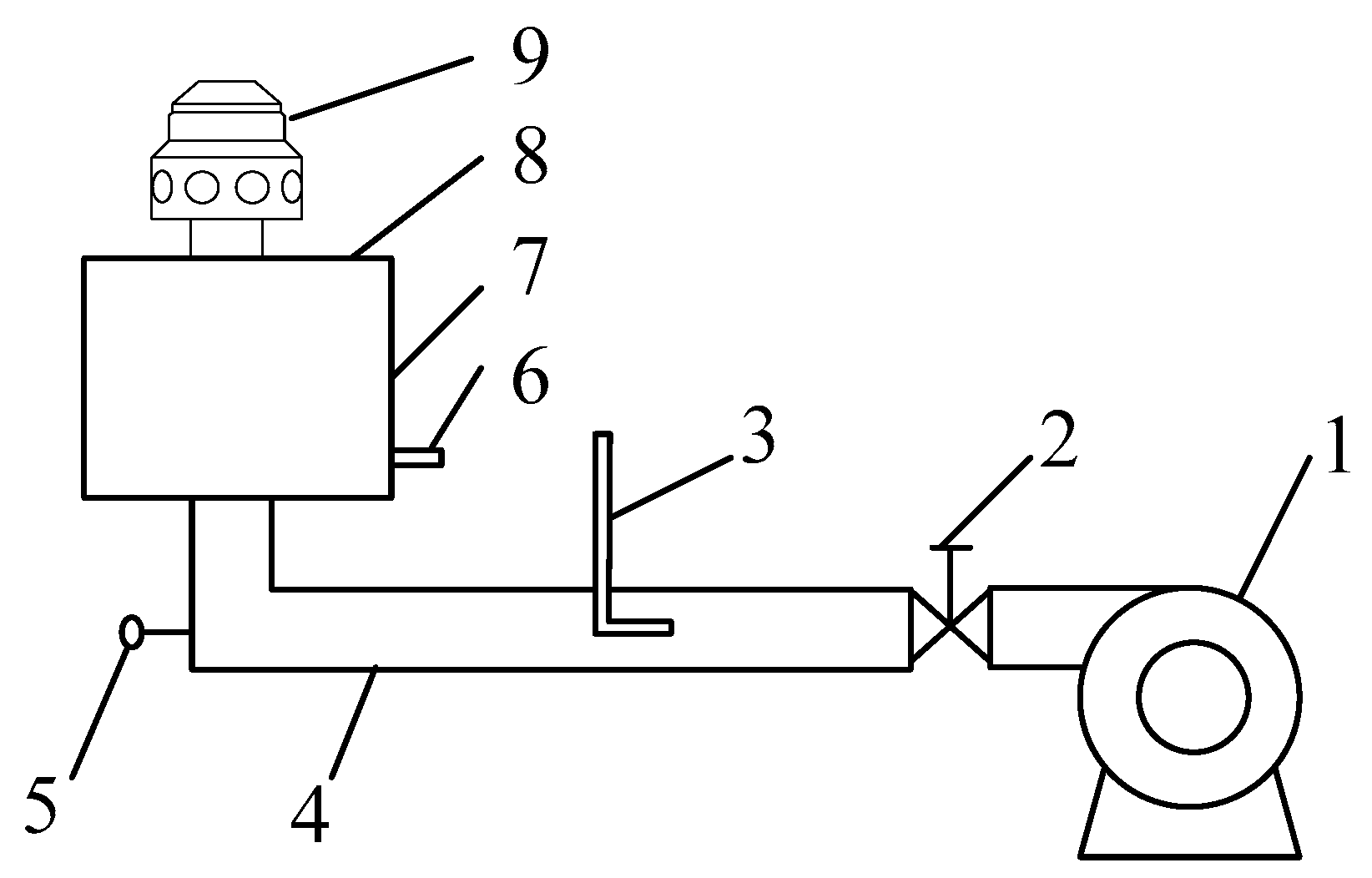
2.1. Cold-State Experiment Rig

In order to better grasp the pressure drop characteristics of bell-type air nozzles, a cold-state experiment rig for the air nozzle was built (as shown in Figure 1). The test rig was mainly composed of a fan, an air flow regulating device, an air flow measuring device, an air duct, a temperature measuring device, an air pressure measuring device, a wind box, a distributor, and an air nozzle.

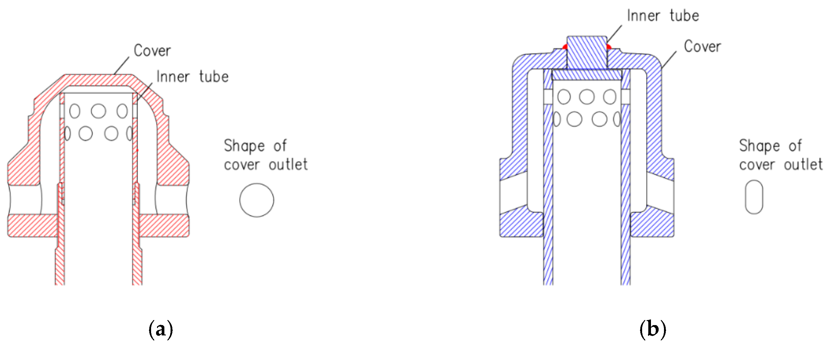
2.2. Structure of Air Nozzles

The pressure drop characteristics of traditional bell-type air nozzles (nozzle A) and the newly-designed bell-type air nozzle (nozzle B) at different air flows were tested by the test rig. The shape, structure, and size of the two air nozzles are shown in Figure 2 and Table 1.
Nozzle A comprised two parts: a cover and an inner tube (as shown in Figure 2a). Its design concept was to adopt the orifice’s structure for the upper part of the inner tube, and outlets on the lower part of the outside cover. Thus, the pressure drop of the air nozzle was mainly formed at the orifices of the inner tube, so that the air nozzle will possess reasonable pressure drop characteristics. Since the outlets on the cover were relatively large, and the air velocity here was relatively slow, it facilitated a reduction in the abrasion of the air nozzle.
The structure of nozzle B is shown in Figure 2b, which replaced the screw threaded connection of nozzle A by top welding and the fixing method. Nozzle B could select a lower outlet velocity in cover than nozzle A, so as to reduce the abrasion of the air nozzle. At the same time, the outlets of the cover were oval structured and inclined downward, which can not only reduce the mutual influence between adjacent air nozzles, but also facilitate the coarse particle flow, such as stones and coal, to avoid blocking.
Since nozzle A is an air nozzle structure that is actually used in engineering, three representative nozzles (A1–A3) were obtained from the site of the cold-state experiment rig: nozzle A1 with large abrasion of outlet holes on the outer cover, nozzle A2 with blocked holes in the outer cover, and nozzle A3 with a gap between the top and outer cover in the deformed inner tube. The three kinds of nozzles are shown in Figure 3.

3. Numerical Simulation

3.1. Numerical Method

The object of this study was to investigate the pressure drop characteristic of bell-type air nozzles. CFD simulations were conducted using the Fluent software (ANSYS Inc., Pittsburgh, PA, USA). Actual operating conditions and properties of CFB boilers were adopted to simulate the flow of the air nozzles. Because the standard k-ε turbulence model adopts the isotropic assumption, the simulation results greatly deviated from the experimental values. The calculation results of the Reynolds Stress Model were difficult to converge. The renormalization group (RNG) k-ε model has a greater calculation accuracy. Therefore, the RNG k-ε was used for calculation. The model was developed by Yokhot and Orszag et al. [27,28] using the RNG method based on the standard k-ε model, which is suitable for the simulation of high-speed gas flow [7,14,29,30,31].

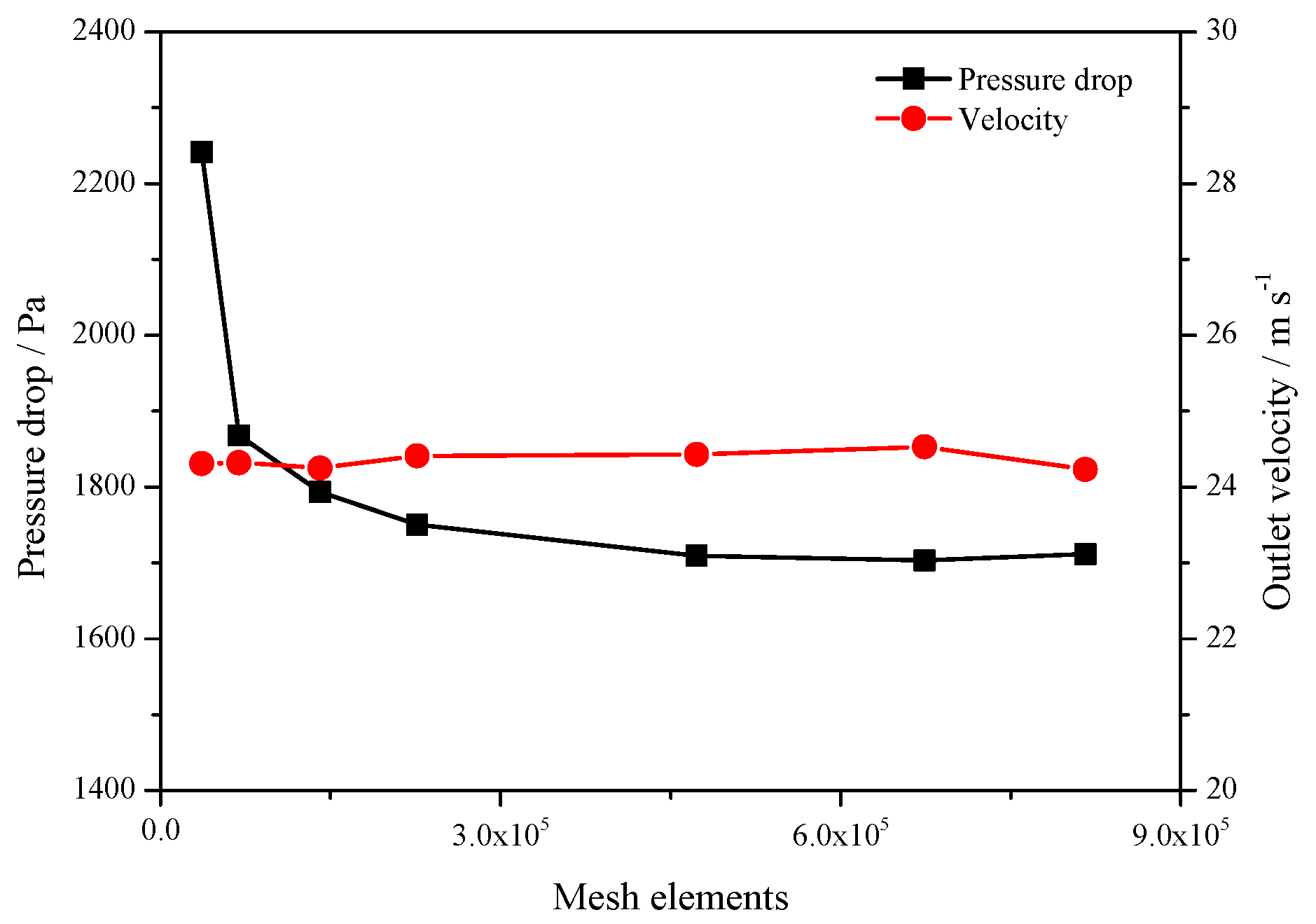
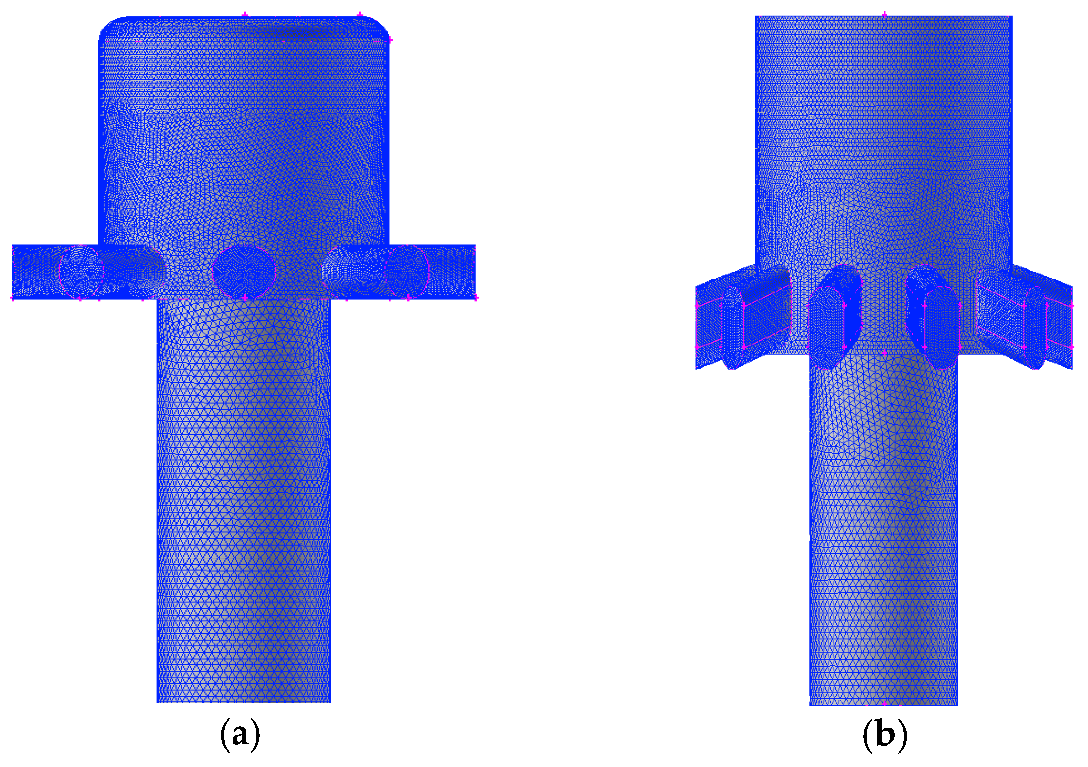
3.2. Computational Mesh

The computational mesh employed an unstructured tetrahedral mesh. In order to adapt large pressure and velocity gradients near small holes of the outer cover and inner tube, a local mesh refinement technique was applied. The mesh number influenced the numerical simulation results, so the mesh independence test was necessary for this study. Seven sets of meshes for nozzle A were generated with mesh from 3.6 × 10⁴ to 8.1 × 10⁵. As shown in Figure 4, the difference in pressure drop and outlet velocity varied little when mesh elements exceeded 6.0 × 10⁵. Finally, the total mesh number of 6.0~8.0 × 10⁵ for the air nozzle is chosen in the following calculations (as shown in Figure 5).

3.3. Boundary Conditions

The pressure and velocity coupling adopted the SIMPLE algorithm, and the momentum and Reynolds stress selected the second order upwind style. In terms of boundary conditions, the velocity inlet and pressure outlet were respectively used for the boundary setting (as shown in Table 2).

4. Results and Discussion

4.1. Cold-State Experiment

Pressure drop [32,33] was the main factor considered when designing and using the air nozzle. The pressure ΔP of the air nozzle during the experiments could be measured by inlet pressure Pinlet and the outlet pressure Poutlet of the air nozzle. It is expressed as follows:
Δ P = P i n l e t P o u t l e t
The pressure drop of the air nozzle was affected by the flow and density of air, and different air nozzle structures also change the pressure drop, which can generally be calculated using Equation (2):
Δ P = 1 2 ζ ρ u 2
ΔP, pressure drop of the air nozzle, Pa.
ζ, resistance coefficient of the air nozzle.
ρ, density of air, kg m−3.
u, inlet velocity of the air nozzle, m s−1.
The resistance coefficient ζ can be determined by the given temperature, pressure, and flow rate of air from Equation (3).
ζ = 2 Δ P ρ u 2 = 2 Δ P ρ 0 273 273 + T 101325 101325 + p ( Q A ) 2
Q, flow rate of air, m3 s−1.
A, inlet area of the air nozzle, m2.
ρ0, density of air in the standard condition, kg m−3.
T, air temperature, °C.
p, ambient pressure, Pa.
Theory suggests that the resistance coefficient of the air nozzle is the same in cold-state and hot-state [7,18]. Therefore, the pressure drop of the air nozzle under hot-state can be calculated from Equation (3).
The test results of resistance coefficients of five air nozzles are shown in Figure 6. It can be seen that the resistance coefficient was basically linear with the inlet velocity of the air nozzle. The average resistance coefficient of nozzle A was 4.482, and the average resistance coefficient of nozzle B was 3.971.
Due to the abrasion of the outer cover outlet in nozzle A1, the outlet diameter of nozzle A generally varied by 22.5 mm. However, outlets on many air nozzles show abrasion after 6 to 10 months, and the diameter of some outlets with abrasion will even reach more than 30~50 mm (as shown in Figure 3a). Due to the increase of the circulation area, the resistance coefficient of nozzle A1 dropped to 3.144. As three outlets in nozzle A2 were blocked (as shown in Figure 3b), the outlet flow area on the outer cover was reduced and the resistance coefficient increased to 5.148. In severe cases, all outlets of the cover were blocked, and the air flows could not pass through. Consequently, the air nozzle lost its function.
The cover and inner tube of nozzle A were installed with screw thread, and there was screw thread deformation and tilting of the inner tube, as the environment in the furnace area is harsh after long-term application. After the inner tube of nozzle A3 was deformed (as shown in Figure 3c), the average resistance coefficient dropped to 3.374 due to the gap (about 5 mm) between the outer cover and inner tube. This difference meant that the cover and the top of the inner tube could not be intimately contacted, and some of the air flowed out from the gap between the cover and the top of the inner tube, changing the pressure drop of the air nozzle (as shown in Figure 7).

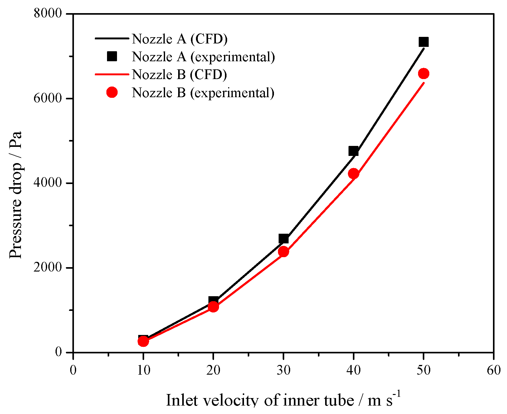
4.2. Simulation Validation

Figure 8 compares the CFD results and cold-state experimental results on pressure drop of nozzle A and nozzle B, and the CFD results were slightly lower than the experimental results. The average deviation of simulation and experimental results of nozzle A was 2.88%, while the average difference of nozzle B was 3.14%, verifying the accuracy of numerical simulation. The cases of nozzle A and nozzle B under 100% load and 30% load were simulated according to the hot-state experiment as shown in Table 3.

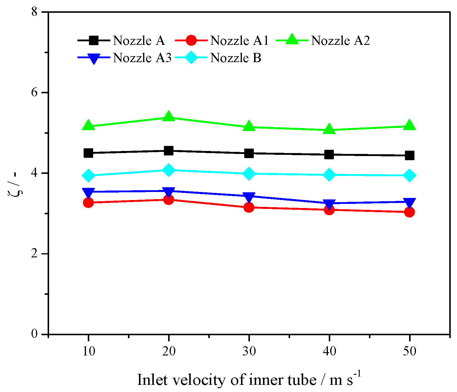
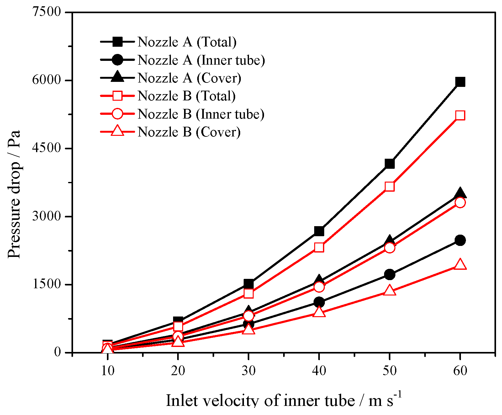
4.3. Pressure Drop Characteristics

The pressure drop of the air nozzle must be compatible with the operating conditions. Excessive pressure drop of the air nozzle under hot-state increases unnecessary energy consumption, while low pressure drop of the air nozzle is likely to cause uneven fluidization, high pressure fluctuations in air plenum, and even slag leakage. The pressure drop change in nozzle A and nozzle B under hot-state was calculated by the CFD method. It can be seen from Figure 9 that the pressure drop in nozzle B was smaller, since the flow area of the outer cover was larger than nozzle A, and the changes in the inner tube showed the opposite trend.
Figure 10 also compares the resistance characteristics of nozzle A and nozzle A3. It can be seen that the airflow from small holes in the inner tube was significantly reduced when there was a gap between the outer cover and inner tube, so that the pressure drop in the inner tube rapidly decreased. The resistance was only 943 Pa at 30% load. In addition, according to the design bed material pressure drop of 5 kPa (30% load), the pressure drop of the air nozzle was only 18.7% of the bed material, which is lower than the recommended value of 20% [7]. The overall resistance data of the air nozzle calculated by numerical simulation show that the pressure drop of the air nozzle decreased when the gap increased, which is consistent with the cold-state experimental results. The above results also explain the reason why some CFB boilers are prone to display slag leakage after replacing the air nozzle. Obviously, the flow area of the inner tube will increase if there is a large gap between the newly replaced air nozzle and original inner tube, and the orifices in the inner tube will not generate sufficient pressure drop. The pressure drop characteristics of a bell-type air nozzle will be destroyed, thus causing a series of problems such as slag leakage. Since there is no gap between the cover and the top of the inner tube in nozzle B, the consistency of pressure drop characteristics of the air nozzle can be guaranteed.
Since the outer cover blockage of air nozzles in CFB boilers is common in the site, the pressure drop and velocity changes after the small holes are blocked in nozzle A and nozzle B under 100% load condition were simulated. It can be seen from Figure 11 that the pressure drop and outlet velocity in nozzle A and nozzle B displayed an increasing trend, but the changes in nozzle B were less than nozzle A. In other words, the operating performance of nozzle B was better than nozzle A as the holes were blocked.

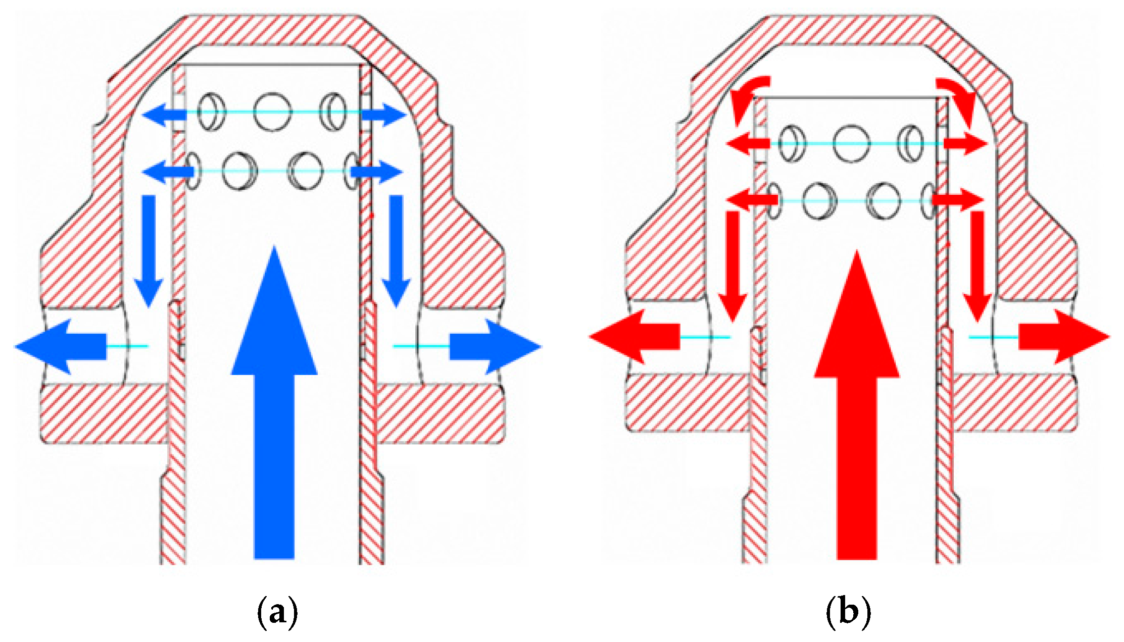
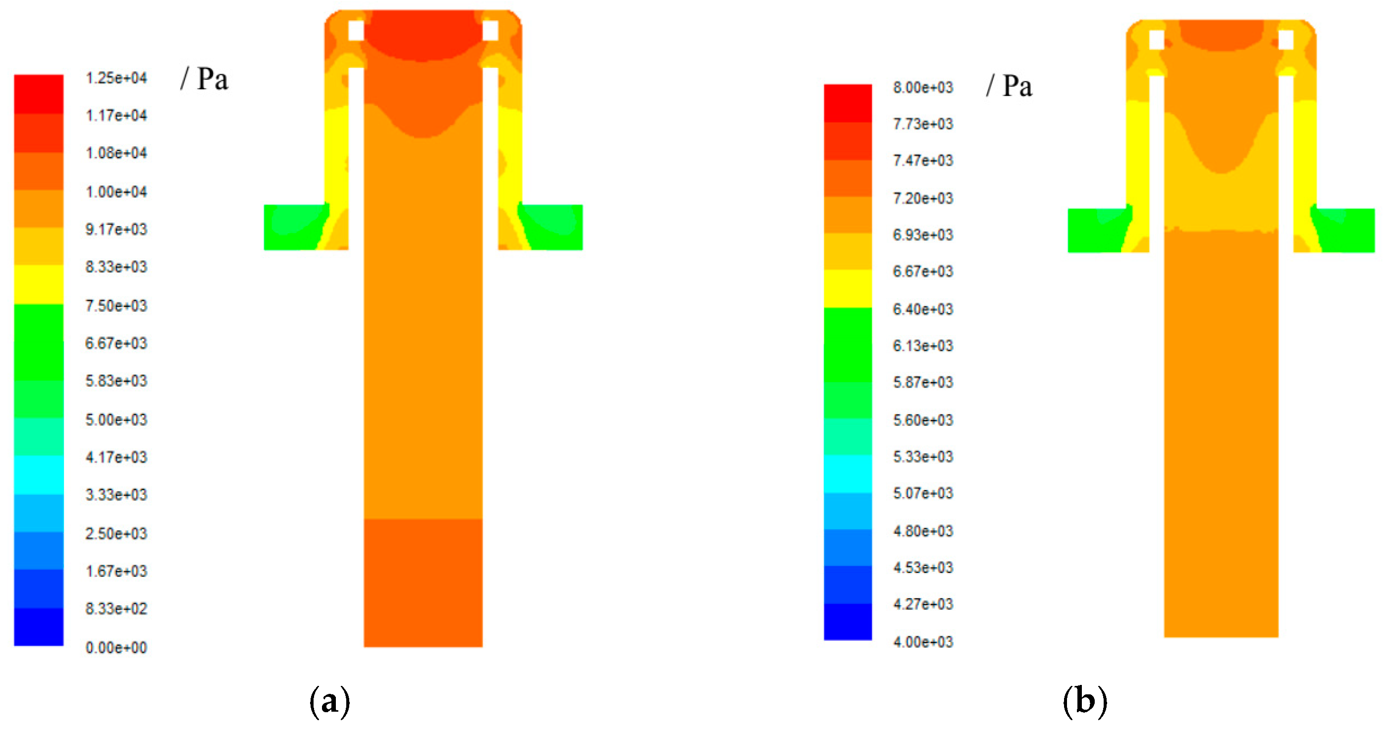
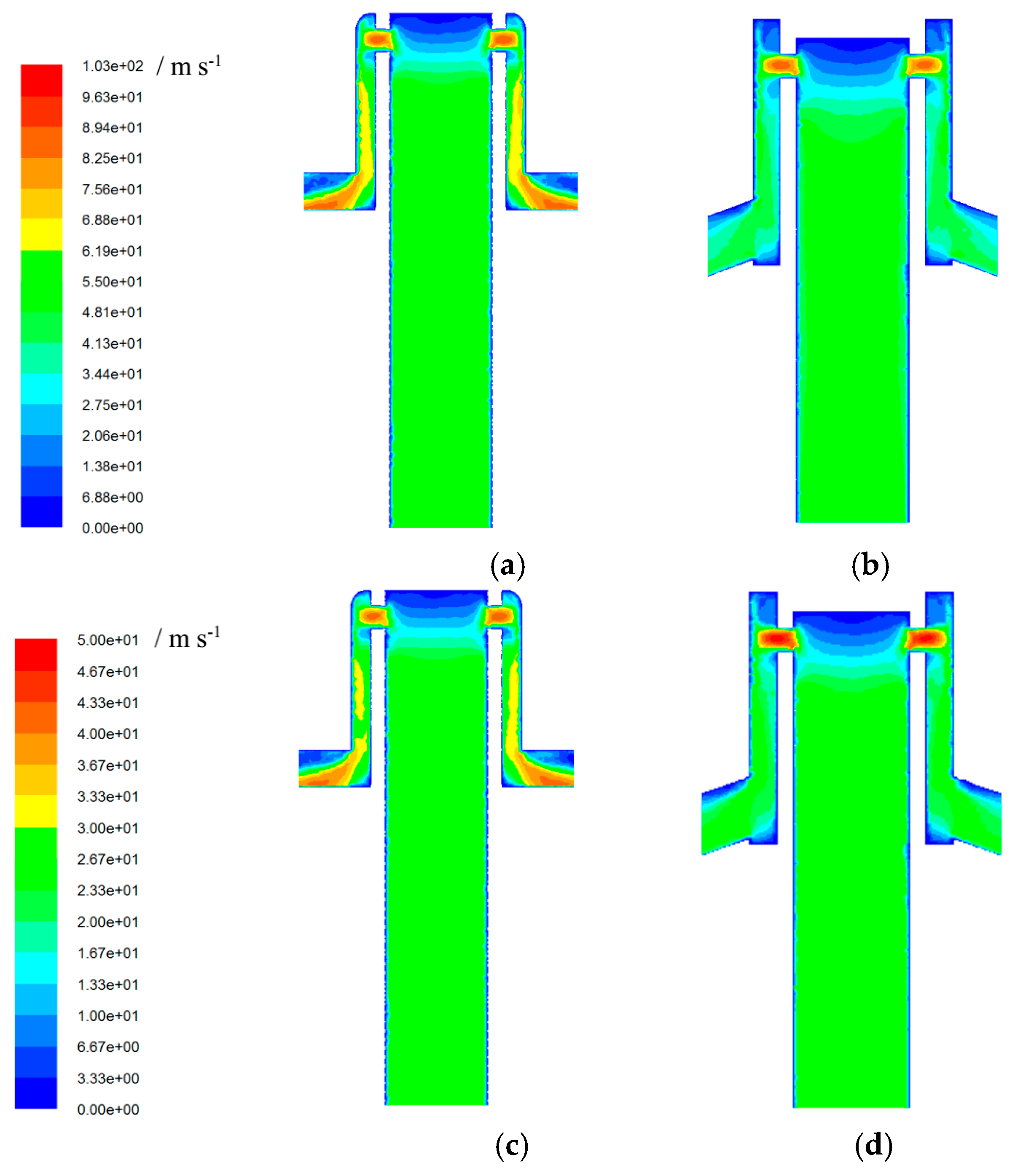
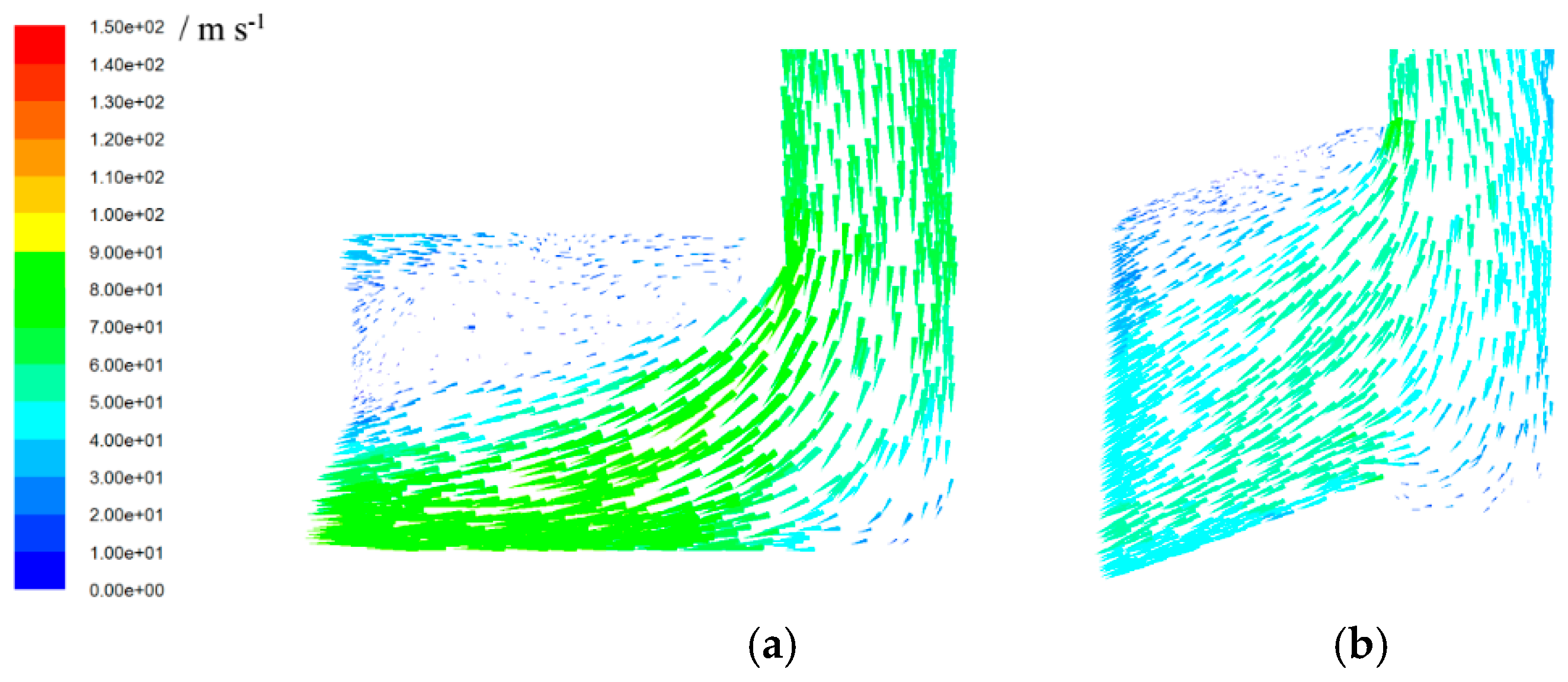
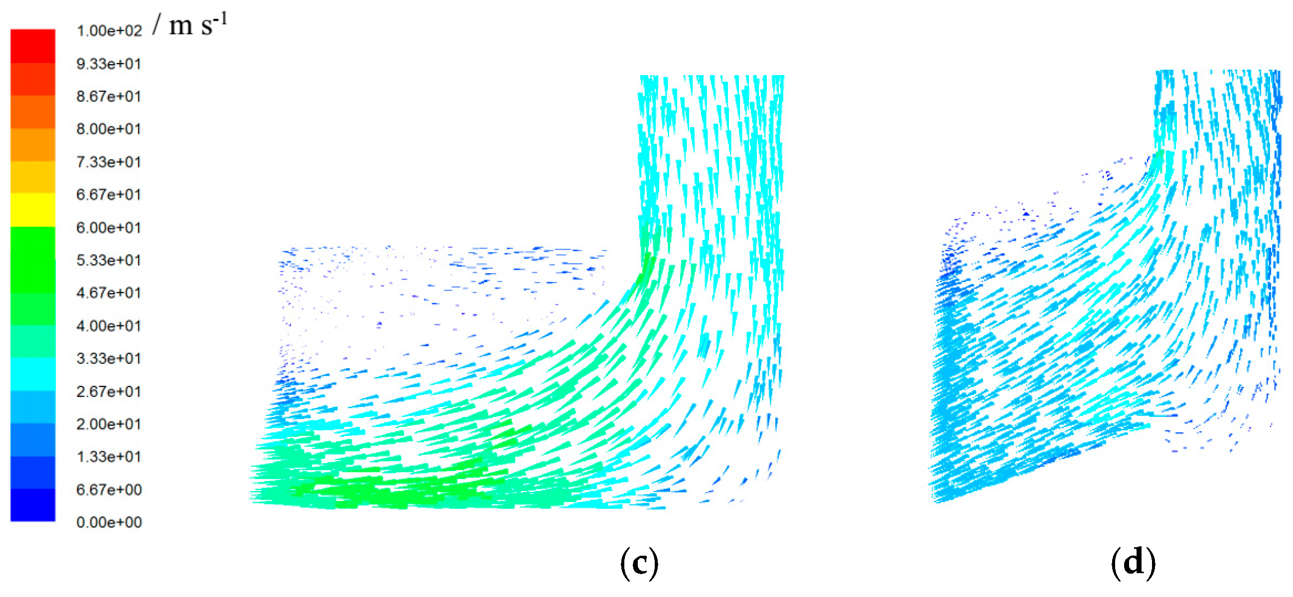
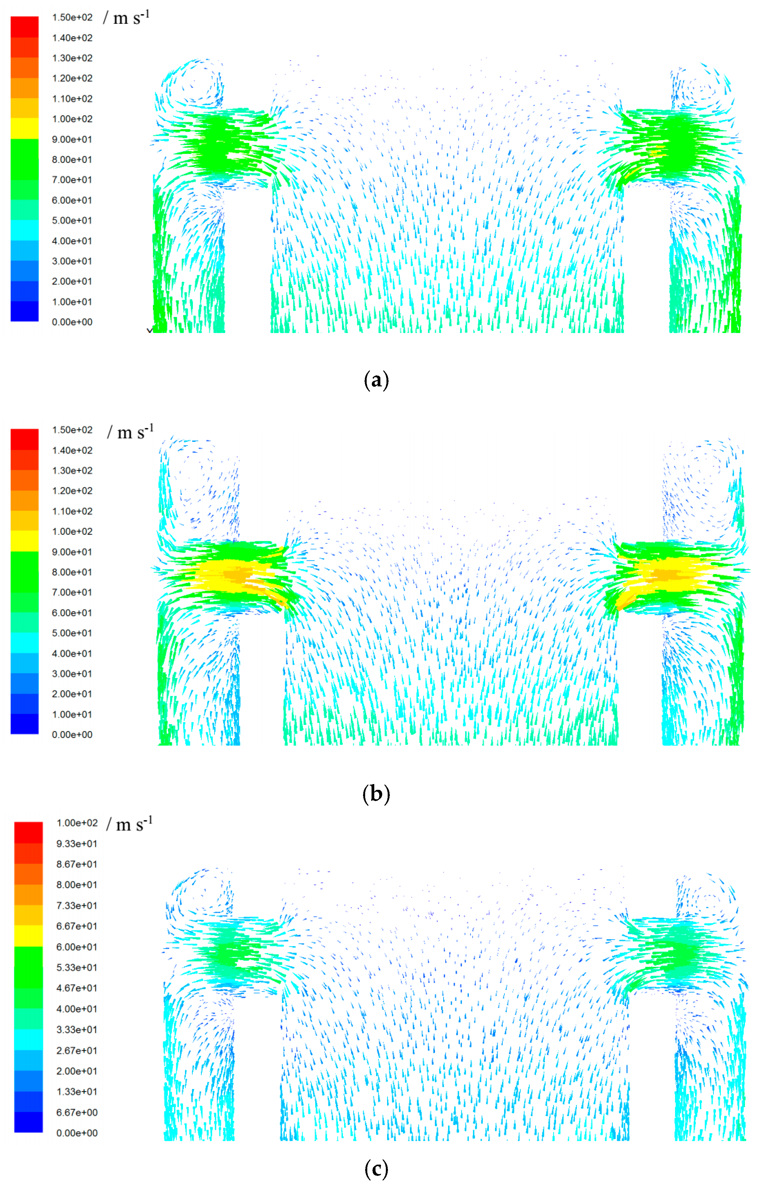
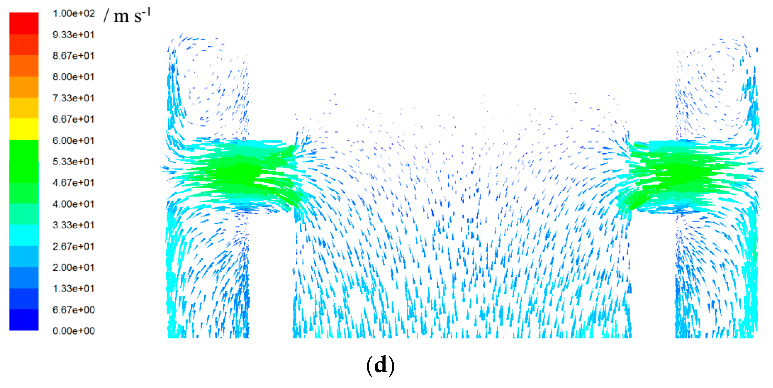
4.4. Flow Characteristics

As can be seen from the velocity simulation results in Figure 12, the outlet velocity difference between nozzle A and nozzle was obvious. Since the small holes in the outer cover of nozzle A were horizontally arranged, the outlet velocity was relatively high at the lower part and relatively low at the upper part (Figure 12a,c), which may have easily caused the particles to be sucked by air at the outlet area. The outlet of nozzle B was a downward special-shaped small hole, and the velocity distribution was quite uniform (as shown in Figure 12b,d), so there was almost no recirculation zone. This feature prevented particles from being drawn into the air nozzle. Therefore, the risk of being blocked for nozzle B was less than nozzle A. At the same time, the risk of inner tube abrasion and slag leakage was also reduced.
As can be seen from the velocity vector in small holes of the outer cover in Figure 13, the airflow was emitted at a higher velocity at the bottom of nozzle A’s outlet, which may have caused the abrasion of the surrounding air nozzles. Nozzle B had a lower outlet velocity and better uniformity, and its downward small holes arrangement facilitated reduction of abrasion of the jet to the surrounding air nozzles, which is very important for extending the service life of an air nozzle.
Figure 14 shows the velocity vector distribution of airflow in the upper part of the inner tube in nozzle A and nozzle B. It can be seen that the airflow velocity in nozzle B was higher than nozzle A.

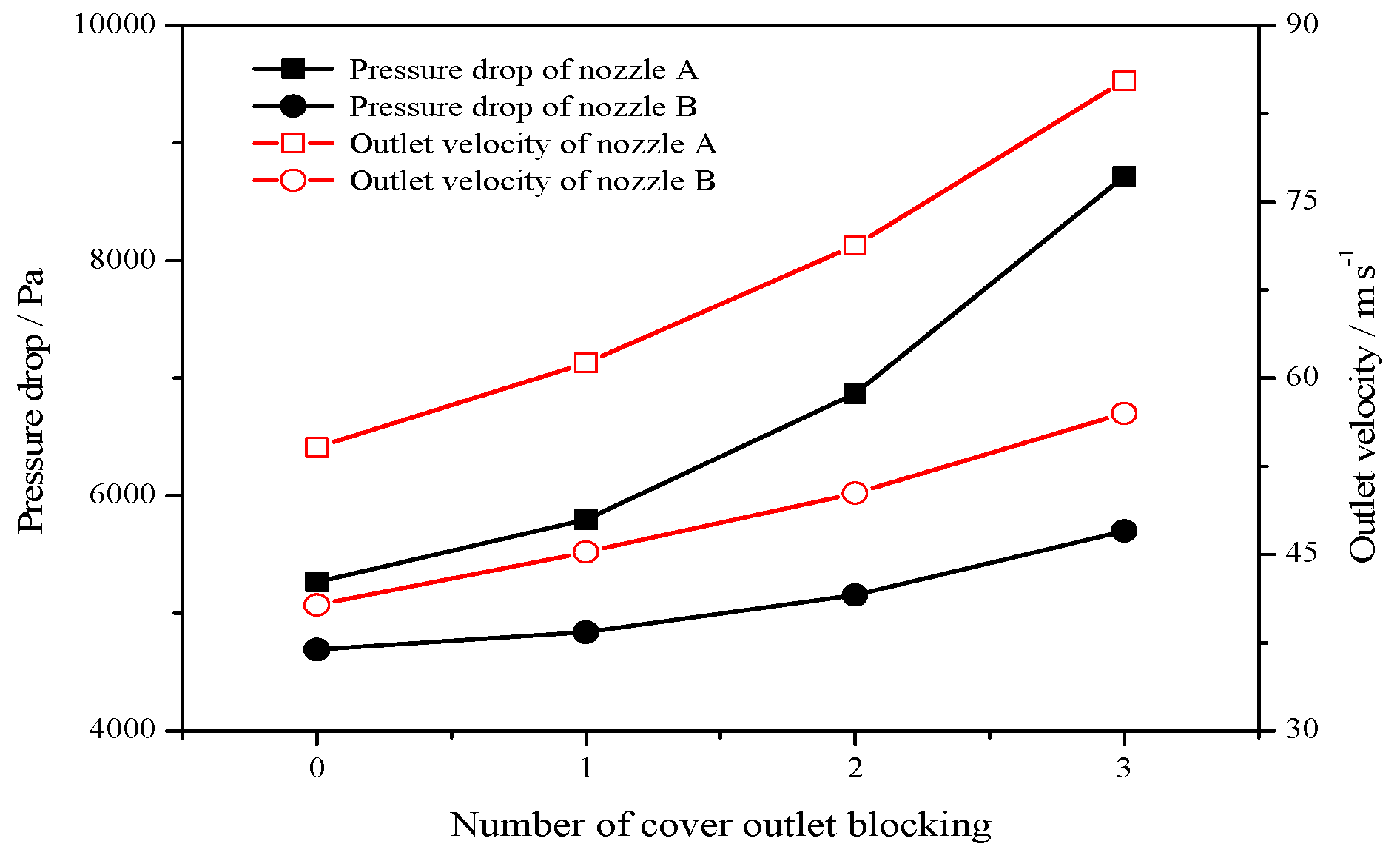
4.5. Engineering Applications

The 480 t h−1 CFB boiler in a power plant is installed with a 715 nozzle A on the grid with a diameter of 159 mm and horizontal and vertical intercept of 270 mm. Affected by the abrasion and blockage of holes in covers and the fracture of inner tubes, more than 420 air nozzles are replaced within an 8500 h operation cycle. The replacement rate reaches 34.5% within 5000 h, causing a high maintenance cost.
When nozzle A is replaced with nozzle B (as shown in Figure 15) with the same number and arrangement, the minimum fluidized air flow of a CFB boiler can be reduced to 100,000 m3/h (under standard conditions) after the air nozzle is rebuilt, which is significantly lower than the previous volume of 140,000 m3/h (under standard conditions) before transformation. The fluidized air flow can be maintained at a low level during the operation of the boiler. At present, nozzle B has been applied for more than 24,000 h, and the replacement rate is only 2.6% within 5000 h, indicating that the service life of the air nozzle is significantly extended.

5. Conclusions

The new bell-type air nozzle scheme is designed to overcome the inherent defects of traditional bell-type air nozzles. Through the cold-state experiment and numerical simulation, the pressure drop characteristics of the new bell-type air nozzle were determined. The following research conclusions were obtained.
(1)
For the bell-type air nozzle, results of the numerical simulation agree with those of the cold-state experiment.
(2)
This paper has conducted simulations for nozzle A and nozzle B at 100% load and 30% load under hot-state, the results indicating that the performance index of nozzle B is better than nozzle A.
(3)
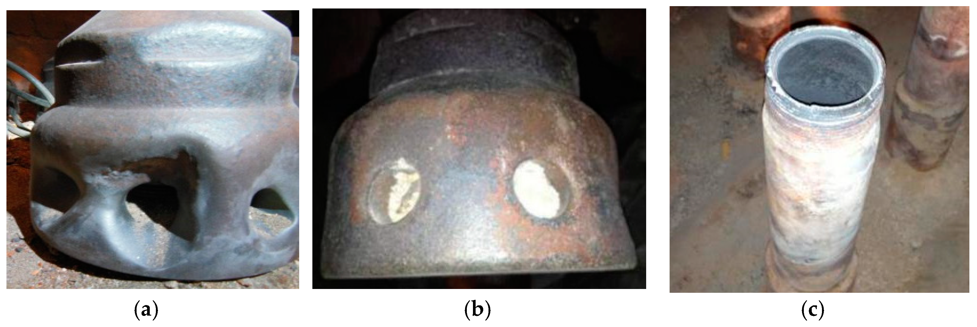
The resistance coefficient of nozzle A will rise after the outer cover is blocked. The abrasion of the outer cover, the generation of a gap between the inner tube and the top of the outer cover, will reduce the resistance coefficient.
(4)
The small hole in the outlet of nozzle B is designed as a downward special shape, and the outlet velocity is evenly distributed. Therefore, the risk of the outer cover clogging is less than nozzle A.
(5)
The application results of a 480 t h−1 CFB boiler show that the air nozzle replacement rate is reduced from 34.5% within 5000 h to 2.6% after replacing nozzle A with nozzle B, and the service life of the air nozzle is significantly extended.
(6)
The related research is of great value for the design and working characteristics evaluation of the bell-type air nozzle. The new bell-type air nozzle has important engineering application potential.

Author Contributions

Writing—Review & Editing, Z.H. and L.D.; Project administration, D.C.

Funding

This study was supported by the Beijing Nova Program (XX2018033).

Acknowledgments

Lin Chen and Lei Tan provided valuable advice on the study idea and write-up.

Conflicts of Interest

The authors declare no conflict of interest. The funders had no role in the design of the study; in the collection, analyses, or interpretation of data; in the writing of the manuscript, and in the decision to publish the results.

Abbreviations

AInlet area of air nozzle (m2)
uInlet velocity of air nozzle (m s−1)
pAmbient pressure (Pa)
PinletInlet pressure of air nozzle (Pa)
PoutletOutlet pressure of air nozzle (Pa)
ΔPPressure drop of air nozzle (Pa)
TAir temperature (°C)
QFlow rate of air (m3 s−1)
ζResistance coefficient of air nozzle (−)
ρDensity of air (kg m−3)
ρ0Density of air under standard condition (kg m−3)

References

  1. Leckner, B. Fluidized bed combustion: Mixing and pollutant limitation. Prog. Energy Combust. Sci. 1998, 24, 31–61. [Google Scholar] [CrossRef]
  2. Basu, P. Combustion of coal in circulating fluidized-bed boilers: A review. Chem. Eng. Sci. 1999, 54, 5547–5557. [Google Scholar] [CrossRef]
  3. Rydén, M.; Hanning, M.; Corcoran, A.; Lind, F. Oxygen Carrier Aided Combustion (OCAC) of Wood Chips in a Semi-Commercial Circulating Fluidized Bed Boiler Using Manganese Ore as Bed Material. Appl. Sci. 2016, 6, 347. [Google Scholar] [CrossRef]
  4. Yue, G.; Cai, R.; Lu, J.; Zhang, H. From a CFB reactor to a CFB boiler—The review of R&D progress of CFB coal combustion technology in China. Powder Technol. 2017, 316, 18–28. [Google Scholar]
  5. Yue, G.; Lu, J.; Yang, H.; Su, H. Research on supercritical circulating fluidized bed boiler. In Proceedings of the 11th International Conference on Fluidized Bed Technology, Beijing, China, 4–17 May 2014; pp. 541–550. [Google Scholar]
  6. Basu, P. Circulating Fluidized Bed Boilers: Design, Operation and Maintenance; Springer International Publishing AG: Cham, Switzerland, 2015. [Google Scholar]
  7. Huang, Z. Optimization Technologies of Circulating Fluidized Bed Boiler; China Electric Power Press: Beijing, China, 2019. [Google Scholar]
  8. Sun, Z.; Jin, B.; Zhang, M.; Liu, R.; Zhang, Y. Experimental study on cotton stalk combustion in a circulating fluidized bed. Appl. Energy 2008, 85, 1027–1040. [Google Scholar] [CrossRef]
  9. Zeng, B.; Lu, X.; Gan, L.; Shu, M. Development of a novel fluidized bed ash cooler for circulating fluidized bed boilers: Experimental study and application. Powder Technol. 2011, 212, 151–160. [Google Scholar] [CrossRef]
  10. Whitehead, A.; Dent, D. Influence of distributor pressure drop uniformity on large fluidized-bed systems. AIChE J. 1982, 28, 169–172. [Google Scholar] [CrossRef]
  11. Qureshi, E.; Creasy, D. Fluidised bed gas distributors. Powder Technol. 1979, 22, 113–119. [Google Scholar] [CrossRef]
  12. Li, Q.; Zhang, Y.; Meng, A. Design and application of novel horizontal circulating fluidized bed boiler. In Proceedings of the 20th International Conference on Fluidized Bed Combustion, Xi’an, China, 18–21 May 2009; pp. 206–211. [Google Scholar]
  13. Yue, G.; Lu, J.; Zhang, H.; Yang, H.; Zhang, J.; Liu, Q.; Li, Z.; Joos, E.; Jaud, P. Design theory of circulating fluidized bed boilers. In Proceedings of the 18th International Fluidized Bed Combustion Conference, Toronto, Canada, 22–25 May 2005; pp. 18–21. [Google Scholar]
  14. Huang, Z.; Xiao, P.; Jiang, J.; Sun, X. Optimal Retrofit of Domestic 200 MW CFB Boilers Air Nozzle. In Proceedings of the CSEE, Wuhan, China, 21–22 August 2011; Volume 31, pp. 183–186. [Google Scholar]
  15. Mirek, P.; Mirek, J.; Sekret, R.; Nowak, W. Nozzles in CFB Boilers, Circulated Fluidized Bed Technology VIII; International Academic Publishers/World Publishing Corporation: Hangzhou, China, 2005; pp. 877–884. [Google Scholar]
  16. Mirek, P.; Nowak, W. The influence of air distributor’s geometry on combustion conditions in large—Scale CFB boiler. Arch. Thermodyn. 2008, 29, 37–44. [Google Scholar]
  17. Mirek, P. Designing of primary air nozzles for large—Scale CFB boilers in a combined numerical—Experimental approach. Chem. Eng. Proc. Process Intensif. 2011, 50, 694–701. [Google Scholar] [CrossRef]
  18. Yang, H.; Huang, Z.; Yue, G.; Lu, J. Characteristics of a Float Nozzle Designed for CFB Boilers. Chem. Eng. Technol. Indust. Chem. 2007, 30, 1398–1400. [Google Scholar] [CrossRef]
  19. Johnsson, F.; Larsson, G.; Leckner, B. Pressure and flow fluctuations in a fluidized bed—Interaction with the air—Feed system. Chem. Eng. Sci. 2002, 57, 1379–1392. [Google Scholar] [CrossRef]
  20. Depypere, F.; Pieters, J.; Dewettinck, K. CFD analysis of air distribution in fluidized bed equipment. Powder Technol. 2004, 145, 176–189. [Google Scholar] [CrossRef]
  21. Dhotre, M.; Joshi, J. Design of a gas distributor: Three—Dimensional CFD simulation of a coupled system consisting of a gas chamber and a bubble column. Chem. Eng. J. 2007, 125, 149–163. [Google Scholar] [CrossRef]
  22. Hughes, T. Scale Model Testing of JEA Northside Units 1 and 2 Primary Air Distribution System and Windbox. Ph.D. Thesis, Tennessee Technological University, Cookeville, TN, USA, 2013. [Google Scholar]
  23. Tong, J.C.; Sparrow, E.M.; Abraham, J.P. Geometric strategies for attainment of identical outflows through all of the exit ports of a distribution manifold in a manifold system. Appl. Therm. Eng. 2009, 29, 3552–3560. [Google Scholar] [CrossRef]
  24. Bhasker, C. Simulation of air flow in the typical boiler windbox segments. Adv. Eng. Softw. 2002, 33, 793–804. [Google Scholar] [CrossRef]
  25. Sekret, W.; Nowak, W. Analysis of the bottom part of a large technical scale circulating fluidized bed boiler. Arch. Thermodyn. 2006, 27, 31–52. [Google Scholar]
  26. Mirek, P.; Klajny, M. Air nozzle design criteria for protection against the backflow of solids in CFB boilers. Appl. Therm. Eng. 2018, 141, 503–515. [Google Scholar] [CrossRef]
  27. Speziale, C.; Thangam, S. Analysis of an RNG based turbulence model for separated flows. Int. J. Eng. Sci. 1992, 30, 1379-IN4. [Google Scholar] [CrossRef]
  28. Smith, L.; Reynolds, W. On the Yakhot—Orszag renormalization group method for deriving turbulence statistics and models. Phys. Fluids A Fluid Dyn. 1992, 4, 364–390. [Google Scholar] [CrossRef]
  29. Serrano, J.R.; Novella, R.; Gomez-Soriano, J.; Martínez, P.J. Computational Methodology for Knocking Combustion Analysis in Compression-Ignited Advanced Concepts. Appl. Sci. 2018, 8, 1707. [Google Scholar] [CrossRef]
  30. Tan, P.; Sha, Y.; Bai, X.; Tu, D.; Ma, J.; Huang, W.; Fang, Y. A Performance Test and Internal Flow Field Simulation of a Vortex Pump. Appl. Sci. 2017, 7, 1273. [Google Scholar] [CrossRef]
  31. Wang, Y.; Shi, D.; Zhang, D.; Xie, Y. Investigation on Unsteady Flow Characteristics of a SCO2 Centrifugal Compressor. Appl. Sci. 2017, 7, 310. [Google Scholar] [CrossRef]
  32. Paqnneerselvam, R.; Savithri, S.; Surender, G. CFD simulation of hydrodynamics of gas—Liquid—Solid fluidised bed reactor. Chem. Eng. Sci. 2009, 64, 1119–1135. [Google Scholar] [CrossRef]
  33. Pei, P.; Wu, G.; Zhang, K.; Yu, B.; Jiang, J.; Wen, D. CFD simulation of jet behaviors in a binary gas—solid fluidized bed comparisons with experiments. Front. Chem. Eng. China 2010, 4, 242–249. [Google Scholar] [CrossRef]
Figure 1. Schematic diagram of cold-state experiment rig. 1—fan; 2—air flow regulating device; 3—air flow speed measuring device; 4—air duct; 5—temperature measuring device; 6—air pressure measuring device; 7—wind box; 8—distributor; 9—air nozzle.
Applsci 09 03805 g001
Figure 2. Schematic diagram of bell-type air nozzle: (a) traditional design (nozzle A); (b) new design (nozzle B).
Applsci 09 03805 g002
Figure 3. Three kinds of nozzle A used in the engineering project: (a) cover of nozzle A1; (b) cover of nozzle A2; (c) inner tube of nozzle A3.
Applsci 09 03805 g003
Figure 4. Mesh independence test.
Applsci 09 03805 g004
Figure 5. Mesh of bell-type air nozzle: (a) nozzle A; (b) nozzle B.
Applsci 09 03805 g005
Figure 6. Resistance coefficients of air nozzles.
Applsci 09 03805 g006
Figure 7. Effect of contact between the cover and inner tube on air flow. (a) the air flow under designed state; (b) the air flow with the presence of a top gap.
Applsci 09 03805 g007
Figure 8. Computational fluid dynamics (CFD) and cold-state experimental results of nozzle A and nozzle B.
Applsci 09 03805 g008
Figure 9. Pressure drop characteristics of nozzle A and nozzle B.
Applsci 09 03805 g009
Figure 10. Pressure field of nozzle A and nozzle A3: (a) nozzle A3 (100% load); (b) nozzle A3 (30% load).
Applsci 09 03805 g010
Figure 11. Resistance characteristics of nozzle A and nozzle B after blocking.
Applsci 09 03805 g011
Figure 12. Velocity field in nozzle A and nozzle B. (a) nozzle A (100% load); (b) nozzle B (100% load); (c) nozzle A (30% load); (d) nozzle B (30% load).
Applsci 09 03805 g012
Figure 13. Outlet velocity vector of the outer covers of nozzle A and nozzle B. (a) nozzle A (100% load); (b) nozzle B (100% load); (c) nozzle A (30% load); (d) nozzle B (30% load).
Applsci 09 03805 g013aApplsci 09 03805 g013b
Figure 14. Inner tube orifices outlet velocity vector of nozzle A and nozzle B. (a) nozzle A (100% load); (b) nozzle B (100% load); (c) nozzle A (30% load); (d) nozzle B (30% load).
Applsci 09 03805 g014aApplsci 09 03805 g014b
Figure 15. Air nozzle arrangement before and after transformation. (a) before transformation (nozzle A); (b) after transformation (nozzle B).
Applsci 09 03805 g015
Table 1. Structure of nozzle A and nozzle B.
DescriptionUnitsNozzle ANozzle B
Inner tubeInternal diametermm6060
External diametermm7676
Number of orifices-1616
Diameter of orificemm1513.5
CoverInternal diametermm103105
External diametermm159159
Number of outlets-810
Diameter of outletmm22.523 *
Angle of outlet-horizontal20°
Fixed method with inner tube-threadedwelding
* equivalent diameter.
Table 2. Boundary conditions and model setting.
ModelSetting
ViscousRNG k-ε
Inlet of inner tubeVelocity-inlet
Outlets of coverPressure-outlet
Wall functionStandard wall function
MomentumSecond order upwind
Pressure-velocity couplingSIMPLE
Table 3. Comparison of operating results.
DescriptionUnitsNozzle A (100% Load)Nozzle A (30% Load)Nozzle B (100% Load)Nozzle B (30% Load)
Pressure dropPa5265125346911110
Inlet velocitym s−156.527.156.527.1
Outlet velocitym s−154.125.840.719.3
Air temperature°C200180200180

