1. Introduction
The concept of more electric aircraft was proposed for the replacement of centralized hydraulic power systems with distributed power-by-wire systems because of the promising benefits of higher reliability, increased dynamic performance, convenient maintainability, weight reduction and easier manufacture. The core component of the distributed power-by-wire system using electric power directly has yielded three types of approach, including the electrohydraulic actuator (EHA), the electromechanical actuator (EMA) and the integrated actuation package (IAP) [
1,
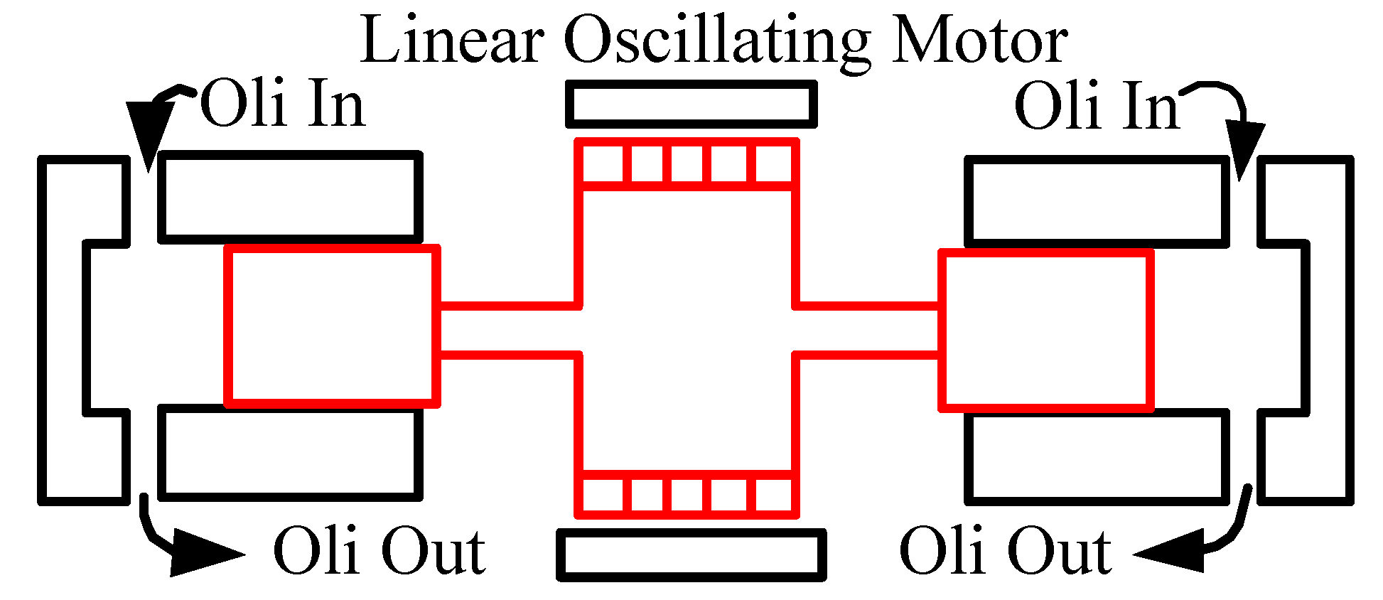
2]. We propose the idea of a linear-driven electrical hydraulic actuator (LEHA) which is required to be of high frequency and large output force. The linear pump is driven by a linear oscillating motor (LOM), as shown in
Figure 1, so it is of great importance to have detailed research on the LOM, especially on the dynamic performance of the LOM with external force loads.
The linear motor, providing reciprocating motion without any other ancillary components, was proposed in America more than a century ago. At the beginning of the exploration of the linear motor, Kemper in Germany proposed a kind of magnetically levitated vehicle propelled by linear motor. After that, LOMs related to the maglev became hot spots until the end of 1990s when the low loss short-stroke LOM became increasingly popular. Actually, linear motors have vital and typical applications on machine tool slid tables, recorders and free piston engines. Since 1999, LOMs especially LOMs have been vitally and extensively applied to air compressors, pumps, electromagnetic valves, active shock absorbers, vibrators and earphones [
3,
4,
5,
6,
7]. The application of LOMs to the LEHA, a kind of hydraulic pump controlled actuator, leads to consequence of good reliability, high power density and convenient maintenance, which requires excellent dynamic displacement output with external load force and large force output. So it is promising to study LOM dynamic performance as well as efficiency in order to apply the LOM better to the LEHA.
Until now, most research has concentrated on force output, motor design and optimization, and control strategy of LOMs. Zhu explored the permanent magnetic array, the thrust force capability, the optimal design parameters, etc. to improve the static output force and reduce the cogging force [
8,
9,
10,
11,
12]. As for the force control, some internal forces of the LOM such as cogging force, detent force, ripple force and force of friction have been taken consideration into the trajectory track of LOMs. LU took the cogging force into compensation control to improve the industrial gantry position control accuracy, but no external load is considered except for the friction force [
13]. A detent force compensation control was conducted by Wang without any external force involved [
14]. Lin had a proposal of a field-programmable gate array (FPGA)-based computed force system to improve the position control performance of the linear ultrasonic motor for various reference trajectories with no load force acting on the LOM [
15]. Hwang applied the Jacobian linearization observer to the ripple force compensation control to improve the position trajectory accuracy [
16]. All these research works above focused on the LOM itself, not taking multiple external force loads such as spring force, rectangular force and damping force into consideration to study the dynamic performance of the LOM. Therefore, it is meaningful and offers promising prospects to have research on the effects of multiple external force loads on the trajectory track of the LOM and it is necessary to develop a linear oscillating load system (LOLS) for the LOM.
As for force loads forms, there are four types including magnetic powder brake, compressed air, weight and voice coil motor (VCM). The magnetic powder brake, a kind of traditional and mature instrument for a rotary motor, is unsuitable for the LOM load simulation because of its ability to impose rotary damping force on the shaft. Even though a pinion and rack transmission mechanism is adapted to transforming linear motion to rotary motion, the transformed motion is in swing and affected severely, and is not ideal rotary motion, which causes unavailability of the magnetic powder brake function. Consequently, direct force loads drew researchers’ attention. Compressed air is usually applied to the simulation of air load for air compressor testing [
17], but this type of force load is deficient and improper for simulating the hydraulic force load because of severe elasticity and non-direction. The suspended weight can provide constant force load on the LOM. Yang added weights on the LOM as the constant force load for the study of the thrust force harmonies [
18]. Cao also applied weights to a complementary and modular linear flux-switching permanent-magnet motor on the force control research [
19]. Although weight force loads have the feature of constant and stability, this type of force load would add redundant inertia to the mover of LOM, which will have serious influence on the LOM dynamic performance, and the weight force loads are limited because of the gravity limitation. The VCM was applied by Katalenic to the short stroke reluctance linear actuator for the high-precision force control [
20], but the performance of the VCM was of partial development, and the output force of the VCM was small. In summary, all these research works lack dynamic performance analysis of the LOM with multiple external force loads, which limited applications and popularization of the LOM. Therefore, it is promising to design a linear oscillating loading system and search effects of different load modes and force amplitudes on the dynamic performance of the LOM, and this work will have significant influence on the application of the LOM to the LEHA, to promote the development of the More Electrical Aircraft (MEA).
In the paper, the design and prototype of the linear oscillating load system, based on the VCM, is introduced in
Section 2; a mathematical model of the LOLS is given in
Section 3; Simulation analysis and experimental results of the dynamic performance of the LOM are introduced in
Section 4; finally, a conclusion is drawn in
Section 5.
3. Mathematical Model of Linear Oscillating Loading System
For the LOM is of excellent symmetry and linearity, it is available to assume that the LOM is of ideal relationship between output thrust force and input current. Hence, the electromagnetic force of the LOM can be written as:
where
is the electromotive force of the LOM to be tested,
is the force constant coefficient of the LOM,
is input current.
Analogously, the electromagnetic force function of the VCM can be written as:
where
is the output thrust force regarded as load force of the VCM,
is the force constant coefficient of the VCM, and
is the input current.
Assume that movers are rigid bodies and ignore deformation of the force sensor, the dynamic equation of the LOLS, based on the Newton second law, can be written as:
where
is the spring stiffness of the LOM;
is the mover mass of the LOM;
is the otal mass of the VCM mover and the sensor mechanism;
is the kinetic friction force of the LOM, and
is the kinetic friction force of the VCM.
Similarly, the dynamic equation of the LOM can be written as:
where
is force magnitude between the force sensor and the LOM.
Approximately, the dynamic equation of the load mechanism can be written as:
where
and
are the coupled forces of action and reaction. Thus, the force equivalency equation, based on the Newton third law, can be written as:
As for the LOM, voltage is composed of three parts, i.e., resistance voltage, inductance voltage and electromotive force (EMF) voltage, so the voltage balance equation of the LOM can be written as:
where
is the input voltage of the LOM,
is the total resistance accorded with series and parallel mode of the LOM coils.
is the total inductance accorded with
.
Similarly, the voltage balance equation of the VCM can be written as:
where
is the input voltage of the VCM,
is the total resistance accorded with parallel mode of the VCM coils.
is the total inductance accorded with
.
In this paper, three typical types of force loads are set to be achieved, i.e., spring force, damping force and rectangular force. For
is regarded as the load force, the relationship between
x and
i2 should be given as follows:
If simulation force is spring force, the relationship between
x and
i2 can be written as:
is the spring stiffness of the spring simulation force. If the simulation force is a damping force, the relationship between
x and
i2 can be written as:
is damping coefficient of the damping simulation force.
If the simulation force is a rectangular force, the relationship between
x and
i2 can be written as:
is the gain coefficient of the rectangular simulation force.
4. Simulation and Experiment Analysis
According to the mathematical model built above, the block diagram of the LOLS can be constructed, as shown in
Figure 12.
As can be seen in
Figure 11, the block diagram can be separated as two parts, i.e., the VCM to provide the thrust load force at the upper block diagram, and the LOM to be tested at the lower block diagram. X
r1 is the reference signal of the LOM and X
r2 is the input signal of the VCM, accorded with f(x), so three types of load forces, i.e., spring force, damping force and rectangular force, can be simulated. Based on the block diagram of the LOLS designed above, both simulation analyses and experimental verification can be carried out to research the dynamic performance of the LOM with a multiple external force load.
4.1. Simulation Analysis
Main parameters values of the LOLS are shown in
Table 1.
Based on the mathematical model and the block diagram of the LOLS built above, the simulation analysis of the dynamic performance of the LOM with external spring force load can be finished as shown in
Figure 13, and the simulated spring stiffness is 133.33 N/mm, 66.67 N/mm and 33.33 N/mm corresponding to amplitude force of 400 N, 200 N and 100 N, respectively.
As can be seen in
Figure 13, spring forces affect both phase responses and amplitude responses as the phases advance by 8.78°, 5.62° and 0.65°, and the amplitude responses reduce by 5.5%, 4.1% and 2.7%, corresponding with amplitude forces of 400 N, 200 N and 100 N respectively, compared with no load. So phase advances and amplitude attenuation extend as the simulated spring stiffness becomes bigger.
Similarly, the dynamic performance of the LOM with external damping force loads is depicted in
Figure 14, corresponding with the amplitude damping forces of 200 N and 400 N respectively.
As it can be seen in
Figure 14, damping forces have an effect on amplitude responses particularly as the amplitude responses reduce by 6.1% and 11.5% corresponded with the amplitude damping forces 200 N and 400 N respectively, compared with no load. Damping forces merely affect the amplitude responses; as the amplitude damping force is bigger, the amplitude attenuation is bigger.
Similarly, the dynamic performance of the LOM with external rectangular force loads is depicted in
Figure 15, corresponding to the amplitude rectangular forces of 200 N and 400 N respectively.
As can be seen in
Figure 15, rectangular forces have effects on the position outputs, especially on the amplitude responses as these reduce by 16.6% and 8.5% corresponding with the amplitude rectangular forces of 200 N and 400 N respectively, compared with no load. Rectangular forces have effects on the amplitude responses more seriously than effects of damping forces at the same force load amplitude.
For these three types of force load, damping force and rectangular force only has effects on the amplitude response as the bigger the amplitude force is, the bigger the amplitude attenuation, while the spring force have effects not only on the amplitude response but also on the phase response as the bigger the amplitude force is, the bigger the amplitude attenuation and phase advance are. Because the spring stiffness is increased owing to the added spring load, to raise the cut-off frequency of the LOM leads to smaller phase lag.
4.2. Experiment Results
Based on the linear oscillating load system built above, experiments are finished to analyze the dynamic performance of the LOM with multiple external force loads, i.e., spring load, damping load and rectangular load. Position outputs of the LOM under multiple force loads are depicted in
Figure 16,
Figure 17 and
Figure 18, respectively.
As can be seen in
Figure 16, the experimental result indicates that the spring force load affects both phase responses and amplitude responses. As the phases advance by 7.2°, 14.4° and 25.2°, and the amplitude attenuations increase by 7.4%, 14.9% and 19.2%, according to different amplitude spring force loads of 100 N, 200 N and 400 N, respectively. Experimental results and simulation results shown in
Table 2 and
Table 3 have the same effects on the amplitude and the phase lag to be smaller. Although impacts between simulation and experiment are different because of different closed loop controls and differences between physical model and mathematical model, the trend is similar.
As can be seen in
Figure 17, damping forces mainly compress the amplitude of the output position as the amplitude attenuations increase by 9.3% and 16.3% accorded with the amplitude damping force loads of 200 N and 400 N, respectively.
As can be seen in
Figure 18, rectangular forces mainly compress the amplitude of the output position as the amplitude attenuations increase by 9.8% and 26% according to the amplitude rectangular force loads of 200 N and 400 N, respectively. Experimental results and simulation results of damping force and rectangular force loads shown in
Table 4 and
Table 5 indicate that damping force and rectangular force mainly have effects on the amplitude attenuation.
The analyses above are to show dynamic performance of the LOM with multiple types of force loads, but the robustness of the controller used in the closed loop of the LOM is inadequate. If an external force compensation control strategy is applied to the closed loop control of the LOM, the amplitude of the rectangular force can be 800 N, as depicted in
Figure 19.


