Article

Analysis and Design of a Novel Concept Gasket to Improve the Reliability of the Balanced Armature Receiver Used in Earphones

1
School of Mechanical Engineering, Pusan National University, Pusan 46241, Korea
2
School of Mechatronic Engineering and Automation, Shanghai University, Shanghai 200444, China
*
Author to whom correspondence should be addressed.
Appl. Sci. 2019, 9(18), 3661; https://doi.org/10.3390/app9183661
Submission received: 6 July 2019 / Revised: 1 August 2019 / Accepted: 1 September 2019 / Published: 4 September 2019
(This article belongs to the Section Mechanical Engineering)

Abstract

:
Currently, balanced armature (BA) receivers are frequently used in earphones, owing to their small size and superior sound quality. However, the reliability of BA receiver earphones has become a considerable challenge, as they easily fail when subjected to external forces, especially during drop impacts. In addition, the original gasket cannot protect the BA receiver well. Therefore, this article focuses on improving the reliability of BA receiver earphones by designing a novel concept for the gasket. Based on a simplified model and analysis methods, the maximum von Mises stress on the armature with different drop directions and the maximum von Mises stress point must first be determined. The gasket was divided into two parts, one for linking and the other for shock absorption. This article focused on the design of the shock absorption structure. A novel concept gasket was proposed, and the analysis results showed that the gasket improved the shock absorption performance. For demonstrating the validity of the shock absorption performance of the novel concept gasket, three confirmatory experiments were performed: the drop impact test, X-ray photography, and sound performance, which included the sound pressure level and total harmonic distortion. The analysis results were experimentally verified.

1. Introduction

Two dominant types of commercial receiver designs exist for translating electrical signals into acoustic signals: dynamic receivers (also known as moving-coil receivers) [1,2,3] and balanced armature (BA) receivers [4,5]. Products with BA receivers are becoming increasingly popular because of their small size and high sound quality. On account of these advantages, BA receivers have been extensively employed in stethoscopes, hearing aids, earphones, and smartwatches. Therefore, several kinds of research have been done involving analyses of the electromagnetic and acoustic characteristics of BA receivers using the lumped parameter method [6] to set up the equivalent circuit, and finite element method [7] to divide the BA receiver into finite elements. However, no research exists regarding the reliability of BA receiver application. With the increasing demand for high sound quality, an increased number of BA receivers are being used in earphones, which are a popular product. Nonetheless, it is inevitable that earphones are frequently struck by external forces, especially when dropped from a certain height. Compared to dynamic receiver earphones, BA-receiver earphones are more prone to failure because of their smaller size; a gasket is used to protect the BA receiver, but the original gasket (OG) is not sufficient at preventing the BA receiver from being destroyed. Therefore, this article focuses on improving the reliability of BA receiver earphones by designing a novel concept gasket (NCG).
To begin, the structures of a BA receiver earphone and the BA receiver are introduced, then the failure of the BA receiver is described using observations from the X-ray photos of the BA receiver before and after the drop impact test. The finite element method used in the dynamic problem [8,9,10] was employed to solve the contact problems [11,12,13], which often occur in solid mechanics [14]. After this, the governing equations in the updated Lagrangian formulation [15] are presented, and an explicit dynamic analysis [16] is applied to solve the governing equations. Then, the stress tensor is obtained to calculate the von Mises stress [17] on the armature. Based on the simplified model and the analysis method, the first step involved dropping the BA receiver from different directions to determine which direction causes the maximum von Mises stress on the armature and to determine the maximum von Mises stress point. The drop direction was set, and the point was used as a reference for the subsequent analysis. The second step involved the gasket design; the structure and function of the gasket are first mentioned, followed by the main text concerning the design of the shock-absorbing part of the gasket. It is a very new concept to maximize the thickness in the limited internal space, and then to design the shock absorption structure [18,19] by adding air regions. The solid gasket has nothing more than the elasticity of its material for absorbing shock energy, and is without any additional structural benefits. The air regions inside the gasket provide the internal pressure, which can be treated as added elasticity to absorb more shocks; the other part is the linking component, which connects the gasket and the upper case of the earphone. Subsequently, a gasket based on a novel concept was proposed to perform the drop impact analysis, showing a better shock absorption performance than that of the original gasket. The last step was to complete the experiments to verify the validity of the analysis result, in which the novel concept gasket had a better shock absorption performance. Three experiments were performed; the first was the drop impact test; the second was a collection of the X-ray photos of the BA receivers before and after the drop impact test to check for failure of parts of the BA receiver. If there was not failure occurring on the BA receiver, especially in the armature, this shows the gasket has a good shock absorption performance. The most critical performance of the BA receiver is the sound performance, and the main approach to check the sound performance is the sound pressure level (SPL) and the total harmonic distortion (THD). Thus, the last experiment involved measuring the sound pressure level [20,21] and total harmonic distortion before and after the drop impact test. Because of this, X-ray photography, SPL, and THD were selected for the criteria of the shock absorption performance. The analysis results were then verified by the experimentation.

2. Analysis Method

2.1. Balanced Armature Receiver Earphone Model

The BA receiver earphone includes an ear tip, a screen, an upper case, a bushing, a lower case, and a cap. The main difference between the dynamic earphone [22] and the BA receiver earphone is the driving core, from which the BA receiver earphone gets its name.
The ear tip improves the earphone touch against human ears and prevents sound leakage. The screen includes the mesh and tape that is used to reduce the peak of the SPL, while the upper case provides the channel for sound propagation. A wire connects the printed circuit board (PCB) of the BA receiver through the bushing and the lower case, and the cap prevents external dust from entering the earphone interior. A cross-sectional view of the BA receiver earphone is shown in Figure 1.

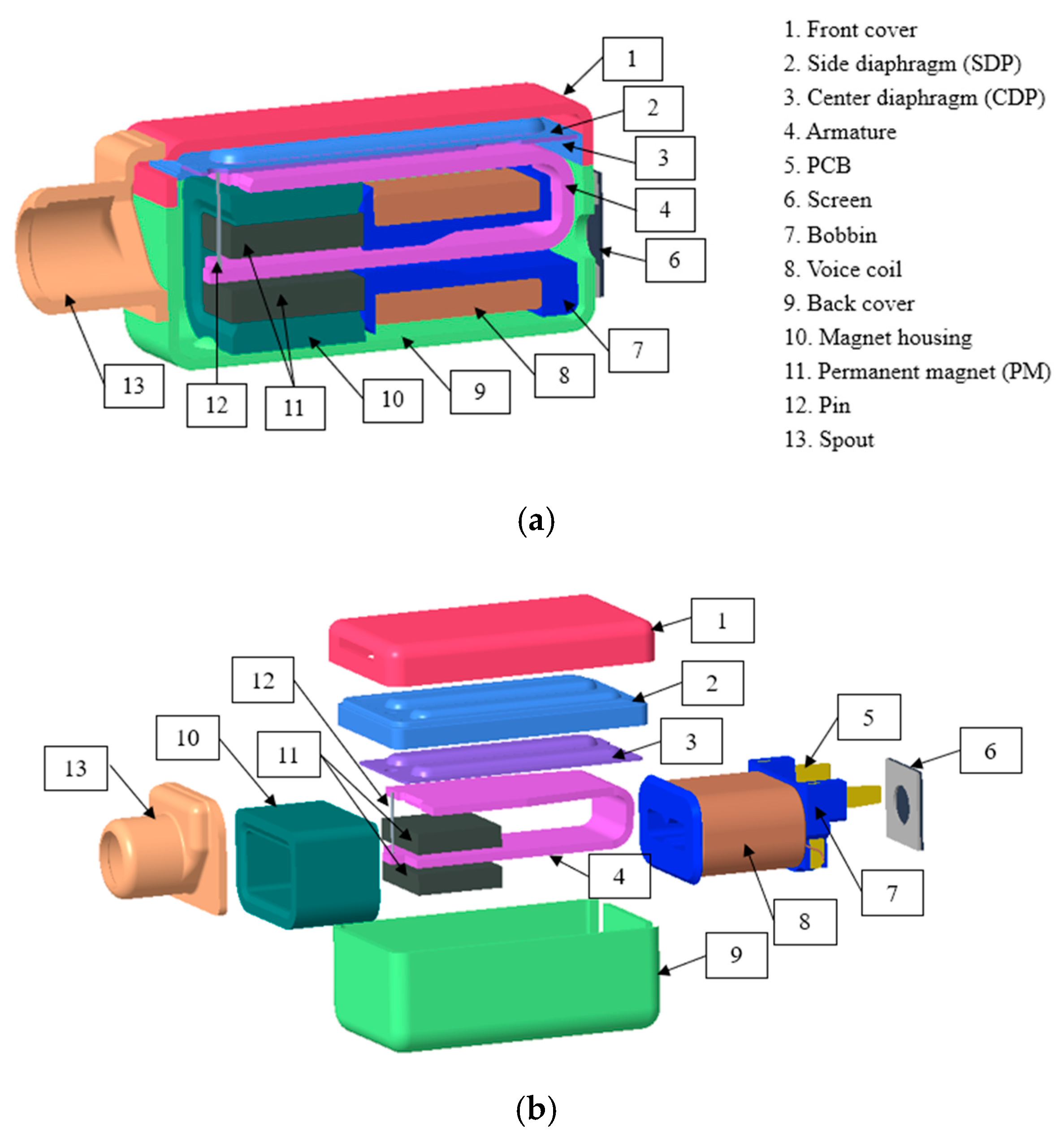
2.2. Balanced Armature Receiver Model

The BA receiver integrates an electromagnetic system, a mechanical vibration system, and an acoustic system. A three dimensional (3D) cross-sectional view of the BA receiver model, with details provided in the exploded view, is shown in Figure 2. The electromagnetic system has an armature, a voice coil, two permanent magnets (PMs), and a magnet housing. The mechanical vibration system includes a drive pin, the center diaphragm (CDP), and the side diaphragm (SDP). Meanwhile, the acoustic system has a front cover, a back cover, and a spout to release the pressure. The armature is the shared part of the electromagnetic system and the mechanical vibration system, which is the core of the BA receiver and retains balance when no forces are acting upon it.
The material properties of the BA receiver include the mechanical and electromagnetic properties, but only the mechanical properties are necessary for this article, as shown in Table 1. As the material of armature is permalloy, which is a nickel–iron magnetic alloy that has excellent magnetic properties, such as high magnetic permeability, but its mechanical properties are enough for subsequent analysis, such as density, Young’s modulus, and Poisson’s ratio. The item labeled “the others” in the table include the drive pin, the spout, and the magnet housing.

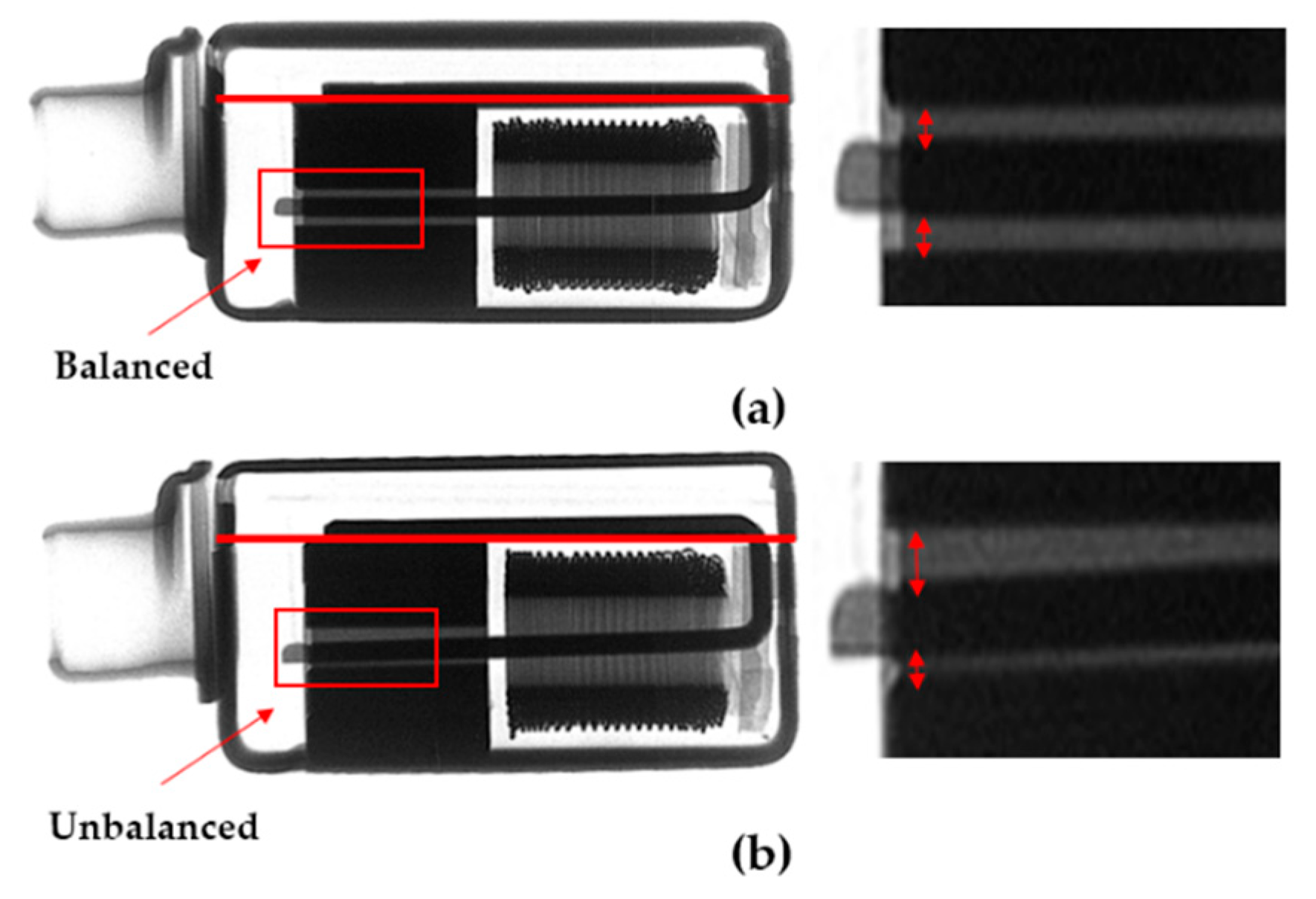
2.3. Failure of the BA Receiver

The BA receiver earphone is one of the most commonly used devices in the world, and it is a widespread phenomenon for earphones to be disabled because of a damaged BA receiver. The experiment results show that the 20 samples had 50% failure when dropped from 1.5 m, with each sample being dropped 15 times. The armature is the core of BA receiver, which connects to the magnet housing by welding. When the armature cannot keep balance anymore, the magnetic circuit of the BA receiver is asymmetric, and it causes the forces acted on the armature to be unbalanced, and in turn lead to an increase in the total harmonic distortion. The X-ray photos of the BA receiver after the drop impact test showed that the armature could no longer retain the balance, as seen in Figure 3.
Therefore, it is necessary to find a good way to protect the BA receivers from the shock damage when dropped from a height of 1.5 m on to a steel plate with a thickness of 0.01 m, one that can be regarded as a rigid body with respect to the BA receiver.

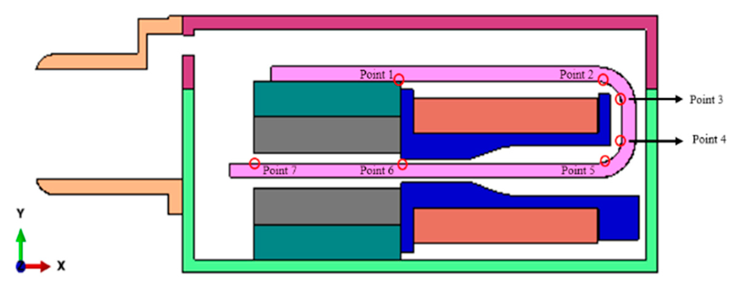
2.4. Numerical Analysis Method

The updated Lagrangian formulation is assumed to have the current configuration V ( x , t ) as the reference configuration. The initial configuration is the space occupied by an object at time t = 0 s, while the current configuration is at a specific time, as seen in Figure 4.
Hence, the governing equations in the updated Lagrangian form are the conservation of mass, momentum, and energy, as follows, respectively:
ρ J = ρ 0 ,
σ x + ρ b = ρ u ¨ ( x , t ) ,
ρ ω i n t t = D ( x , t ) σ ,
where ρ is the material density of the current configuration, J is the Jacobian matrix, ρ 0 is the material density of the initial configuration (t = 0 s), b is the acting force per mass, x is the position, u ( x , t ) is the displacement, u ˙ ( x , t ) is the velocity, u ¨ ( x , t ) is the acceleration, and ω i n t is the internal energy change. The rate of deformation D ( x , t ) is given by
D ( x , t ) = u ˙ ( x , t ) x .
For a linear elastic material:
σ ( x , t ) = E 0 t D ( x , t ) d t = E l n ( F ( x , t ) ) ,
where F ( x , t ) is the deformation gradient.
The initial conditions are as follows:
σ ( x , 0 ) = σ 0 ( x ) ,
u ( x , 0 ) = 0 ,
u ˙ ( x , 0 ) = u ˙ 0 ( x ) .
The essential boundary conditions are
u ˙ ( x , t ) = u ˙ ¯ ( x , t )   for   x Γ v ,
where u ˙ ¯ is the velocity vector, and Γ v is the specified velocity boundary.
The traction boundary conditions are
n σ ( x , t ) = t x ( x , t )   for   x Γ t ,
where n is the unit-length direction vector in the current configuration, t x is the stress vector, and Γ t is the specified surface force boundary.
Compared to the implicit dynamic analysis [23], the explicit dynamic analysis has some advantages regarding solving the complex impact–contact problem, for which the contact time is truly short, such as a low analysis time with high numerical accuracy.
The explicit dynamic analysis used a central difference rule to integrate the equations of motion explicitly through time, using the kinematic conditions at one increment to calculate the kinematic conditions at the next increment. At the beginning of the increment, the program solved for the dynamic equilibrium, which states that the product of the nodal mass matrix M and the nodal accelerations u ¨ is equal to the net nodal forces, i.e., the difference between the external applied forces F and the internal element forces I ; the superscript i refers to the increment number:
M u ¨ ( i ) = F ( i ) I ( i ) .
The accelerations at the beginning of the current increment (time t) were calculated by
u ¨ ( i ) = M 1 · ( F ( i ) I ( i ) ) .
As the explicit procedure always used a lumped mass matrix, solving for the accelerations was trivial. There were no simultaneous equations to solve, and the acceleration of any node was determined completely by its mass and the net force acting on it, which made the nodal calculations very inexpensive. The accelerations were integrated through time using the central difference rule, and this change in velocity was added to the velocity from the middle of the previous increment to determine the velocities at the middle of the current increment:
u ˙ ( i + 1 2 ) = u ˙ ( i 1 2 ) + Δ t ( i + 1 ) + Δ t ( i ) 2 u ¨ ( i ) ,
where u ˙ is the nodal velocity, and Δ t is the time increment; i 1 2 and i + 1 2 refer to the mid-increment values. The velocities were integrated through time and were added to the nodal displacements u at the beginning of the increment to determine the displacements at the end of the increment:
u ( i + 1 ) = u ( i ) + Δ t ( i + 1 ) u ˙ ( i + 1 2 ) .
To estimate the stable time increment size, an approximation to the stability limit is often written as the shortest transit time of a dilatational wave across any of the elements in the mesh:
Δ t L m i n c d ,
where L m i n is the smallest element dimension in the mesh and c d is the dilatational wave speed in terms of λ 0 and μ 0 , defined below.
c d = λ ^ + 2 μ ^ ρ .
In isotropic material, the effective Lamé parameters can be defined as follows:
λ ^ = λ 0 = E υ ( 1 + υ ) ( 1 2 υ ) ,
μ ^ = μ 0 = E 2 ( 1 + υ ) ,
where λ ^ and μ ^ are referred to as Lamé’s first parameter and Lamé’s second parameter, respectively. E is the Young’s modulus, and υ is Poisson’s ratio.
The element calculations included determining the element strains and applying material constitutive relationships (element stiffness) to determine the element stresses, and, consequently, the internal forces. Then, the Cauchy stress tensor can be determined as follows:
σ = [ σ x x σ x y σ x z σ y x σ y y σ y z σ z x σ z y σ z z ] ,
σ x y = σ y x , σ y z = σ z y , σ z x = σ x z .
In material science and engineering, the six components of stress can describe the state of stress at a point in the general 3D domain.
σ v = 1 2 [ ( σ x x σ y y ) 2 + ( σ y y σ z z ) 2 + ( σ y y σ z z ) 2 + 6 ( σ x y 2 + σ y z 2 + σ z x 2 ) ] ,
where σ is the Cauchy stress tensor, σ v is the von Mises stress, and it can also be called the von Mises yield criterion or equivalent tensile stress. σ x x , σ y y , and σ z z are the normal stress, while σ x y , σ y z , and σ z x are the shear stress.
In physics, the strain energy is the energy stored by a system undergoing deformation. For a linear elastic material, the strain energy is
U =   U 0 d V ,
where U 0 is the strain energy density, and V is the volume. For a 3D problem, the strain energy density is given by
U 0 = 1 2 ( σ x x ε x x + σ y y ε y y + σ z z ε z z + σ x y ε x y + σ y z ε y z + σ z x ε z x ) ,
ε x y = ε y x , ε y z = ε z y , ε z x = ε x z ,
where ε x x , ε y y , and ε z z are the normal strain, while ε x y , ε y z , and ε z x are the shear strain.

2.5. Drop Directions

Some parts of the BA receiver were removed, such as the SDP, the CDP, and the drive pin, as they have no significant effect regarding the drop impact analysis. The first step was to determine the drop direction that causes the maximum von Mises stress on the armature; seven points of the armature were set, and five drop directions established to complete the analysis and compare the results. All points, from 1 to 7, were central points of the armature, as shown in Figure 5.
Meanwhile, the drop directions of the BA receiver are shown in Figure 6.
By comparing the analysis results, direction 1 always had the maximum von Mises stress value, followed by direction 2, while direction 5 had the minimum, as directions 1 and 2 were perpendicular to the direction of armature vibration, as shown in Figure 7.
The von Mises stress on the seven points of the armature in direction 1 showed that point 1 had the maximum value, as it was located closest to the connection part between the armature and the magnet housing fixed on the back cover, as shown in Figure 8. Therefore, direction 1 was set as the reference drop direction and point 1 as the reference point.

3. Gasket Design Method

3.1. Gasket Structure

The gasket comprised the linking and shock-absorbing parts, as displayed in Figure 9. The linking part connected the gasket and the upper case of the earphone, while the shock-absorbing part specifically protected the BA receiver as much as possible. The linking part was dependent on the internal shape of the upper case, and, although the linking part also had shock absorption performance, for a better comparison with the original gasket, this article focused on the design of the shock-absorbing part only.

3.2. Shock Absorption Structure Design

For obtaining a better shock absorption structure, the first thing necessary was to increase the thickness of the original gasket until reaching the maximum thickness; and the second was the design of the shock absorption structure to maximize the shock absorption performance. The solid gasket had no more than the elasticity of material for absorbing shocks, without any additional structural benefit. The gasket with air regions had the elasticity of the material plus that provided by a plurality of the air regions formed therein, which could save more material yet have better elasticity than the gasket without air regions. There were four regions in the novel gasket, one upper region (UR) that included the upper air region (UAR) and upper solid region (USR); one lower region (LR) that included the lower air region (LAR) and lower solid region (LSR); and two side regions (SRs) that included the side air region (SAR) and side solid region (SSR). The cross-section of the regional division of the gasket is shown in Figure 10. The maximum von Mises stress decreased with the total thickness of the gasket increase in Figure 11. According to the limitation of the outside space of the BA receiver, the growth of the original gasket’s thickness was limited from 4 mm to 5.7 mm. Thus, the maximum thickness was 5.7 mm. Moreover, rubber was selected as the material by considering the manufacturing process.
The structural shock-absorbing elasticity of air regions represented the relationship between space volume and internal pressure. When the air regions were depressed, the internal pressure increased because of the reduced space. To provide enough support for the BA receiver and also provide sufficient air region volume, the length and width of these air regions were defined by considering manufacturing feasibility at the same time. Moreover, it was also critical to have sufficient solid regions to absorb shocks. Thus, the thickness of the four air regions should be optimized to maintain a balance between the solid regions and the air regions. The thickness of the upper and lower air regions was along the z-axis, while the thickness of side air regions was along the x-axis. The thickness ratio of each region was equal to its air region’s thickness over its region’s thickness, which was the sum of the thickness of its air region and solid region.
Setting the gasket with LAR as the example, the other regions were all solid. The thickness ratio of LR was equal to LAR’s thickness over LR’s thickness, which was the sum of the thickness of LAR and LSR. Others were found to be in the same way. The influence of the thickness ratio of LR on the maximum von Mises stress is shown in Figure 12. The change tendency of the maximum von Mises stress did not decrease linearly with the increase of the thickness ratio—the volume of LAR increased, leading to the provision of more internal pressure, whilst at this time the solid region was still sufficient in absorbing shock. After reaching the critical ratio, the solid region was not enough for absorbing shock, which caused the maximum von Mises stress to increase. When the thickness ratio was 100%, the air regions connected to the outside, and there was no longer any internal pressure for shock. According to the analysis results, when the thickness ratio was 50%, the solid region and the air region had a good balance on absorbing shock. Furthermore, applying the same thickness ratio to the other regions caused the novel concept gasket to come out.
Two kinds of gaskets were employed to perform the final analysis, as shown in Figure 13. One was the original gasket with a total thickness of 4 mm and without any air regions, and the other was the novel concept gasket, designed by increasing the total thickness of the original gasket, and with the addition of air regions.

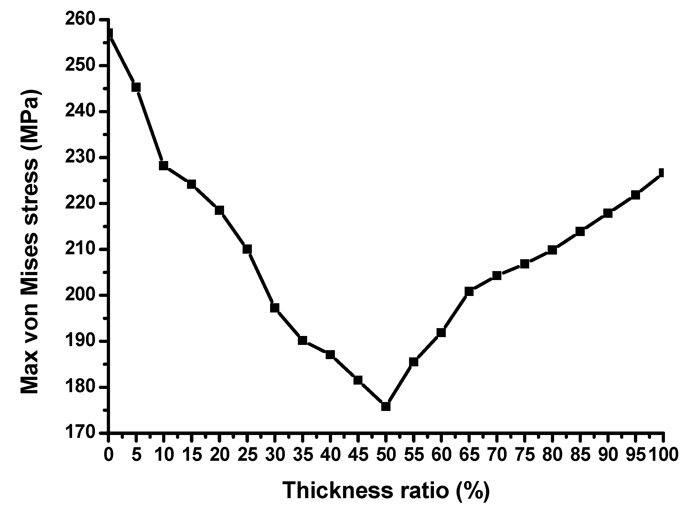
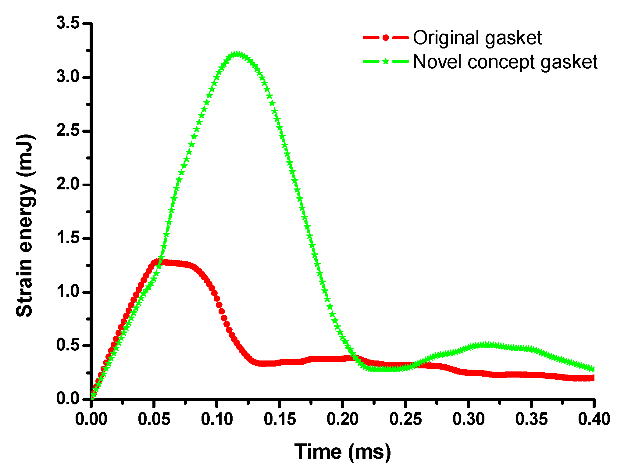
3.3. Gasket Analysis Results

The results of the von Mises stress of the BA receiver without the gasket and the BA receivers with different gasket types are shown in Figure 14. By comparing the results, it was found that the first peak value (512.0 MPa) of the BA receiver without the gasket was reduced and delayed because the original gasket (361.8 MPa) first absorbs the shock when the whole model contacts the steel plate. The maximum von Mises stress of the BA receiver with the novel concept gasket (168.2 MPa) was reduced and delayed again by increasing the thickness and adding the air region. As discussed above, the air regions provide internal pressure to absorb shock. At the same time, the solid regions which, as the major part of the gasket, had material elasticity to absorb shock by deforming.
Moreover, the solid regions had more deformation, not only because of their large volume but also more space. Thus, the strain energy of the novel concept gasket was larger than that of the original gasket, as shown in Figure 15. The time in which the maximum strain energy occurred was the same as that of the maximum von Mises stress, which indicated that the armature had the maximum von Mises stress when the gasket could not absorb any strain energy.
According to the information above, the novel concept gasket had a better shock absorption performance than the original gasket. Hence, the novel concept gasket was selected to perform the experiments for verification of the analysis results.

4. Experiment

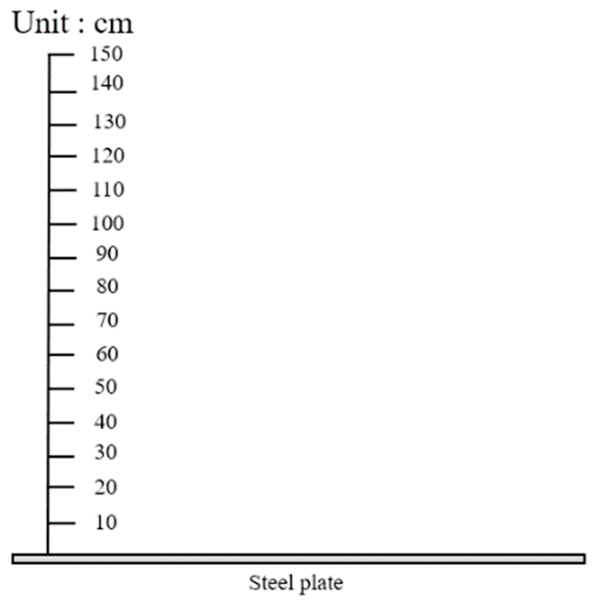
4.1. Experimental Setup

Three kinds of experiments were performed to verify the analysis results, which showed the novel concept gasket to have a better shock absorption performance compared to the original. The first experiment was the drop impact test, the setup of which is shown in Figure 16.
The second experiment involved capturing and comparing the X-ray photos to check whether the BA receiver had a failure after the drop impact test. The setup of the X-ray experiment is shown in Figure 17. The last experiment was measuring the SPL and THD of the BA receiver before and after the drop impact test to check whether the BA receiver was in good working condition or not; the setup of this experiment is shown in Figure 18.

4.2. BA Receiver Earphone Sample

The BA receiver earphone sample included the ear tip, the upper (with screen) and lower cases, and the BA receiver with the gasket, as shown in Figure 19. For better observation of the internal structure of the two kinds of gaskets, cross-sectional views of each are shown in Figure 20.

4.3. Experimental Results
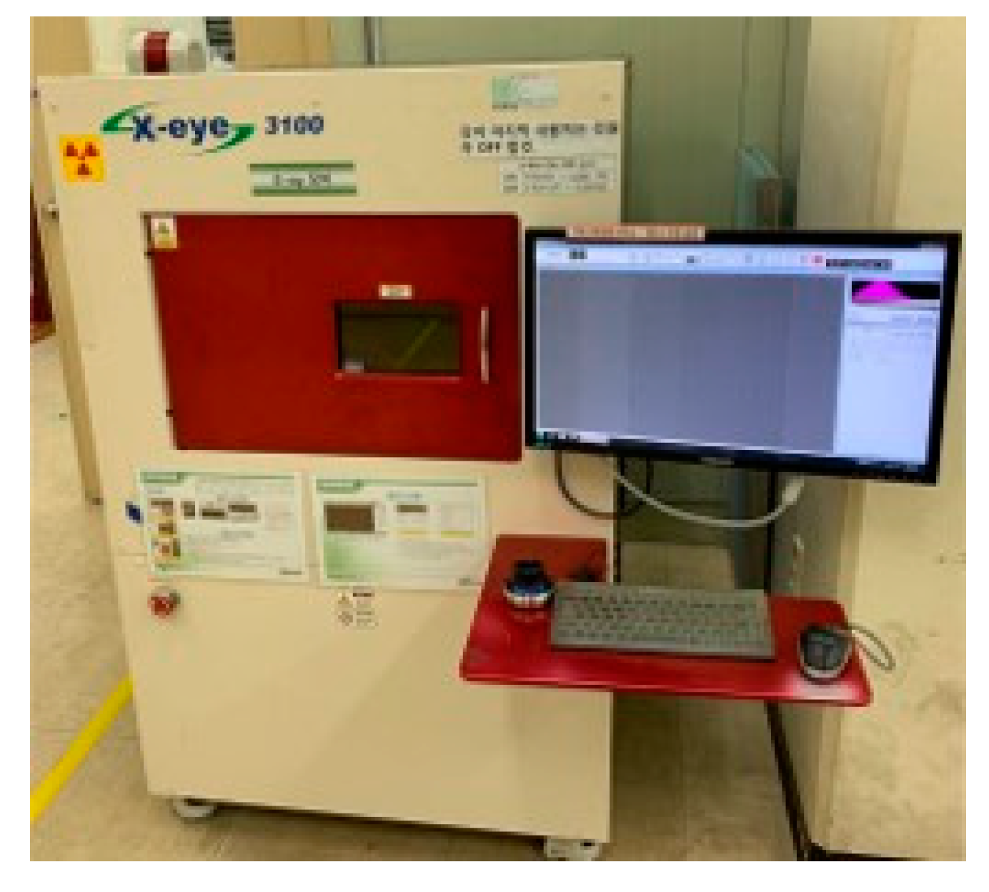
The 40 BA receiver samples were divided into two groups, one being with the original gasket and the other with the novel concept gasket, and each sample was repeated 15 times. Of the samples in the first group, 50% failed, while all samples of the second group were saved. Two samples from each group were selected for the results, labeled No. 1 and No. 2 from group one, and No. 3 and No. 4 from group two. Because of the small size and closure of the BA receiver, it was hard to accurately and directly detect the integrity of the internal structure. Therefore, X-ray photography, sound pressure, and total harmonic distortion were used in this article to detect the integrity and acoustic performance of the BA receiver, reflecting the shock absorption performance of the gasket.

4.3.1. X-ray Photos

X-ray photography was selected to check the integrity of the internal structure of the BA receiver, and the critical point of the X-ray photo was checked in whether the armature kept balance or not. The X-ray photos of these four BA receivers are presented in Figure 21. By comparing them, the armatures of No. 1 and No. 2 were seen to be unbalanced, while those of No. 3 and No. 4 were balanced after the drop impact test. The upper air gap of No. 1 and No. 2 were longer than the lower air gap, which could cause the asymmetry of the magnetic flux without a current and could lead to higher sound harmonic distortion. From these results, the novel concept gasket was proven to better protect the BA receiver. However, to confirm the proper working condition of the BA receiver, the SPL and THD must be measured.

4.3.2. Sound Performance

The sound pressure level and the total harmonic distortion were the critical indexes to measure the sound performance of the earphones. In this article, the SPL and THD were selected to reflect the shock absorption performance. Once the armature could not keep balance after the drop impact test, the THD of the receiver increased more than before the drop impact test. Moreover, the SPL decreased around 3 dB at the low-mid frequency, which is in the primary range of frequencies acceptable to the human ears. The SPLs and THDs of the four BA receivers are shown in Figure 22.
From the figures, on the one hand, the SPLs of No. 1 and No. 2 decreased by 3 dB from 100 Hz to 20 kHz, while No. 3 and No. 4 remained the same without significant differences. On the other hand, the THDs of No. 1 and No. 2 increase by 0.5% from 100 Hz to 20 kHz, while No. 3 and No. 4 did not have significant differences. Hence, samples No. 1 and No. 2 cannot work in good condition after the drop impact test, indicating that the original gasket does not protect the BA receiver sufficiently. However, the SPLs of samples No. 3 and No. 4 verified that the novel concept gasket can protect the BA receiver well. According to the above experiments, the novel concept gasket showed better shock absorption performance.

5. Conclusions

In this study, the drop directions of the BA receiver and the maximum von Mises stress points on the armature were analyzed, and the improved shock-absorbing effect was confirmed using the governing equations in the updated Lagrangian formulation and explicit dynamic analysis. Each part of the earphone was manufactured, particularly the novel concept gasket. Three kinds of experiments were conducted to validate the analysis results. Furthermore, the novel concept gasket exhibited a reduced first peak value of the von Mises stress and absorbed more strain, which was 512.0 MPa when the gasket was not used, but 168.2 MPa when the gasket was used. This result shows a reduction of 67.1%, while the original gasket showed a reduction of 29.3%. Consequently, this study provides a new attempt to investigate the field of the balanced armature receiver and provides an efficient method for the improvement of the reliability of BA receiver earphones.

Author Contributions

Z.-X.J., J.-H.K. and S.-M.H. contributed significantly to the conception of the study; Z.X.J., J.-H.K., and Y.-W.J. performed the data analyses and wrote the manuscript; D.-P.X. and S.-M.H. came out with constructive advice; all authors discussed the results and revised the manuscript.

Funding

This research received no external funding.

Conflicts of Interest

No conflict of interest.

Abbreviations

The following abbreviations are used in this manuscript:
BABalanced armature
OGOriginal gasket
NCGNovel concept gasket
SPLSound pressure level
THDTotal harmonic distortion
PCBPrinted circuit board
PMsPermanent magnets
CDPCenter diaphragm
SDPSide diaphragm
URUpper region
UARUpper air region
USRUpper solid region
LRLower region
LARLower air region
LSRLower solid region
SRsSide regions
SARSide air region
SSRSide solid region

References

  1. Xu, D.P.; Sun, P.; Kwon, J.H.; Hwang, S.M. An integrated design of microspeaker module with smaller volume. J. Appl. Phys. 2014, 115, 17A339. [Google Scholar] [CrossRef]
  2. Jiang, Y.W.; Kwon, J.H.; Kim, H.K.; Hwang, S.M. Analysis and optimization of micro speaker-box using a passive radiator in portable device. Arch. Acoust. 2017, 42, 753–760. [Google Scholar] [CrossRef]
  3. Lu, M.; Xie, Y.; Zhu, W.; Peyton, A.J.; Yin, W. Determination of the magnetic permeability, electrical conductivity, and thickness of ferrite metallic plates using a multi-frequency electromagnetic sensing system. IEEE Trans. Ind. Inform. 2018, 15, 4111–4119. [Google Scholar] [CrossRef]
  4. Jensen, J.; Agerkvist, F.T.; Harte, J.M. Nonlinear time-domain modeling of balanced-armature receivers. J. Audio Eng. Soc. 2011, 59, 91–101. [Google Scholar]
  5. Xu, D.-P.; Jiang, Y.-W.; Hwang, S.-M. Analysis of the Magnetization Effect of Permanent Magnets on the Nonlinear Magnetic Characteristic Distributions of a Balanced Armature Receiver. IEEE Trans. Magn. 2018, 55, 1–5. [Google Scholar] [CrossRef]
  6. Xu, D.-P.; Jiang, Y.-W.; Hwang, S.-M.; Zhang, H.-L. Fast Electromagnetic Analysis of a 3-D Magnetic Circuit in a Balanced Armature Receiver. IEEE Trans. Magn. 2018, 55, 1–4. [Google Scholar] [CrossRef]
  7. Jiang, Y.W.; Xu, D.P.; Jiang, Z.X.; Kim, J.H.; Hwang, S.M. Comparison of Multi-Physical Coupling Analysis of a Balanced Armature Receiver between the Lumped Parameter Method and the Finite Element/Boundary Element Method. Appl. Sci. 2019, 9, 839. [Google Scholar] [CrossRef]
  8. Hughes, T.J. The Finite Element Method: Linear Static and Dynamic Finite Element Analysis; Courier Corporation: North Chelmsford, MA, USA, 2012. [Google Scholar]
  9. Friswell, M.; Mottershead, J.E. Finite Element Model Updating in Structural Dynamics; Springer Science & Business Media: Berlin/Heidelberg, Germany, 2013; Volume 38. [Google Scholar]
  10. Lu, M.; Yin, L.; Peyton, A.J.; Yin, W. A novel compensation algorithm for thickness measurement immune to lift-off variations using eddy current method. IEEE Trans. Instrum. Meas. 2016, 65, 2773–2779. [Google Scholar]
  11. Galin, L.A.; Moss, H.; Sneddon, I.N. Contact Problems in the Theory of Elasticity; North Carolina State University Raleigh School of Physical Sciences and Applied Mathematics: Raleigh, NC, USA, 1961. [Google Scholar]
  12. Hughes, T.J.; Taylor, R.L.; Sackman, J.L.; Curnier, A.; Kanoknukulchai, W. A finite element method for a class of contact-impact problems. Comput. Methods Appl. Mech. Eng. 1976, 8, 249–276. [Google Scholar] [CrossRef]
  13. Yin, W.; Tang, J.; Lu, M.; Xu, H.; Huang, R.; Zhao, Q.; Zhang, Z.; Peyton, A. An equivalent-effect phenomenon in eddy current non-destructive testing of thin structures. IEEE Access 2019, 7, 70296–70307. [Google Scholar] [CrossRef]
  14. Chan, S.K.; Tuba, I.S. A finite element method for contact problems of solid bodies—Part I. Theory and validation. Int. J. Mech. Sci. 1971, 13, 615–625. [Google Scholar] [CrossRef]
  15. Bathe, K.J.; Ramm, E.; Wilson, E.L. Finite element formulations for large deformation dynamic analysis. Int. J. Numer. Methods Eng. 1975, 9, 353–386. [Google Scholar] [CrossRef] [Green Version]
  16. Doyle, J.F. Static and Dynamic Analysis of Structures: With an Emphasis on Mechanics and Computer Matrix Methods; Springer Science & Business Media: Berlin/Heidelberg, Germany, 2012; Volume 6. [Google Scholar]
  17. Mises, R.V. Mechanik der festen Körper im plastisch-deformablen Zustand. Nachr. Ges. Wiss. Göttingen Math.-Phys. Kl. 1913, 1913, 582–592. [Google Scholar]
  18. Huang, C. Air Cushion Grip with a Cubic Supporting Structure and Shock-Absorbing Function. U.S. Patent 5,193,246, 15 March 1993. [Google Scholar]
  19. Huang, J. Shock-Absorbing Cushion. U.S. Patent 5,669,161, 23 September 1997. [Google Scholar]
  20. Kinsler, L.E.; Frey, A.R.; Coppens, A.B.; Sanders, J.V. Fundamentals of Acoustics, 4th ed.; Wiley-VCH: Weinheim, Germany, 1999; p. 560. ISBN 0-471-84789-5. [Google Scholar]
  21. Xu, D.P.; Lu, H.W.; Jiang, Y.W.; Kim, H.K.; Kwon, J.H.; Hwang, S.M. Analysis of sound pressure level of a balanced armature receiver considering coupling effects. IEEE Access 2017, 5, 8930–8939. [Google Scholar] [CrossRef]
  22. Jiang, Y.W.; Xu, D.P.; Jiang, Z.X.; Kim, J.H.; Hwang, S.M. Analysis and Design of Helmholtz Protector to Improve High-Frequency Response of Insert Earphone. Appl. Sci. 2019, 9, 2541. [Google Scholar] [CrossRef]
  23. Sun, J.S.; Lee, K.H.; Lee, H.P. Comparison of implicit and explicit finite element methods for dynamic problems. J. Mater. Process. Technol. 2000, 105, 110–118. [Google Scholar] [CrossRef]
Figure 1. Cross-sectional view of the balanced armature (BA) receiver earphone.
Applsci 09 03661 g001
Figure 2. BA receiver structure: (a) Three dimensional (3D) cross-sectional view; (b) exploded view.
Applsci 09 03661 g002
Figure 3. X-ray photos of the BA receiver (a) before and (b) after the drop impact test.
Applsci 09 03661 g003
Figure 4. Initial and current configurations.
Applsci 09 03661 g004
Figure 5. Seven set armature points.
Applsci 09 03661 g005
Figure 6. Drop directions of the BA receiver.
Applsci 09 03661 g006
Figure 7. von Mises stress on point 1 of the armature for different drop directions.
Applsci 09 03661 g007
Figure 8. von Mises stress on the seven points of the armature for direction 1.
Applsci 09 03661 g008
Figure 9. Cross-sectional view of a gasket: (a) linking part; (b) shock-absorbing part.
Applsci 09 03661 g009
Figure 10. Cross-sectional view of the regional division of the gaskets: (a) 3D view; (b) Two dimensional (2D) yz-axis view; (c) 2D xz-axis view.
Applsci 09 03661 g010
Figure 11. The change tendency of the maximum von Mises stress with an increase of total thickness.
Applsci 09 03661 g011
Figure 12. The influence of the thickness ratio of the lower air region (LAR) on the maximum von Mises stress.
Applsci 09 03661 g012
Figure 13. Cross-sectional view of gaskets: (a) original gasket; (b) novel concept gasket.
Applsci 09 03661 g013
Figure 14. von Mises stress of the BA receivers with and without gaskets.
Applsci 09 03661 g014
Figure 15. von Mises stress of the BA receivers with different gasket types.
Applsci 09 03661 g015
Figure 16. Setup of drop impact test.
Applsci 09 03661 g016
Figure 17. Setup of X-ray experiment.
Applsci 09 03661 g017
Figure 18. Setup of sound pressure level (SPL) experiment.
Applsci 09 03661 g018
Figure 19. BA receiver earphone sample.
Applsci 09 03661 g019
Figure 20. Cross-sectional views of (a) original and (b) novel concept gasket samples.
Applsci 09 03661 g020
Figure 21. X-ray photos of BA receivers (a) No. 1 and No. 2, and (b) No. 3 and No. 4, before and after the drop impact test.
Applsci 09 03661 g021
Figure 22. SPLs of BA receivers (a) No. 1 and No. 2, (b) No. 3 and No. 4, and (c) No. 1 and No. 3 before and after the drop impact test.
Applsci 09 03661 g022aApplsci 09 03661 g022b
Table 1. The material properties of the BA receiver and gasket.
ItemMaterialDensity (kg/m3)Young’s Modulus (GPa)Poisson’s Ratio
ArmaturePermalloy83001270.3
BobbinVectra E130i1610150.43
CDPAluminum2750710.29
GasketRubber13000.0040.5
PMsN50H75001550.3
SDPSoniphor T10um12000.130.36
Voice coilCopper89601100.34
The othersSUS 30478501920.33

