The Prevention and Control Mechanism of Rockburst Hazards and Its Application in the Construction of a Deeply Buried Tunnel

Abstract
1. Introduction
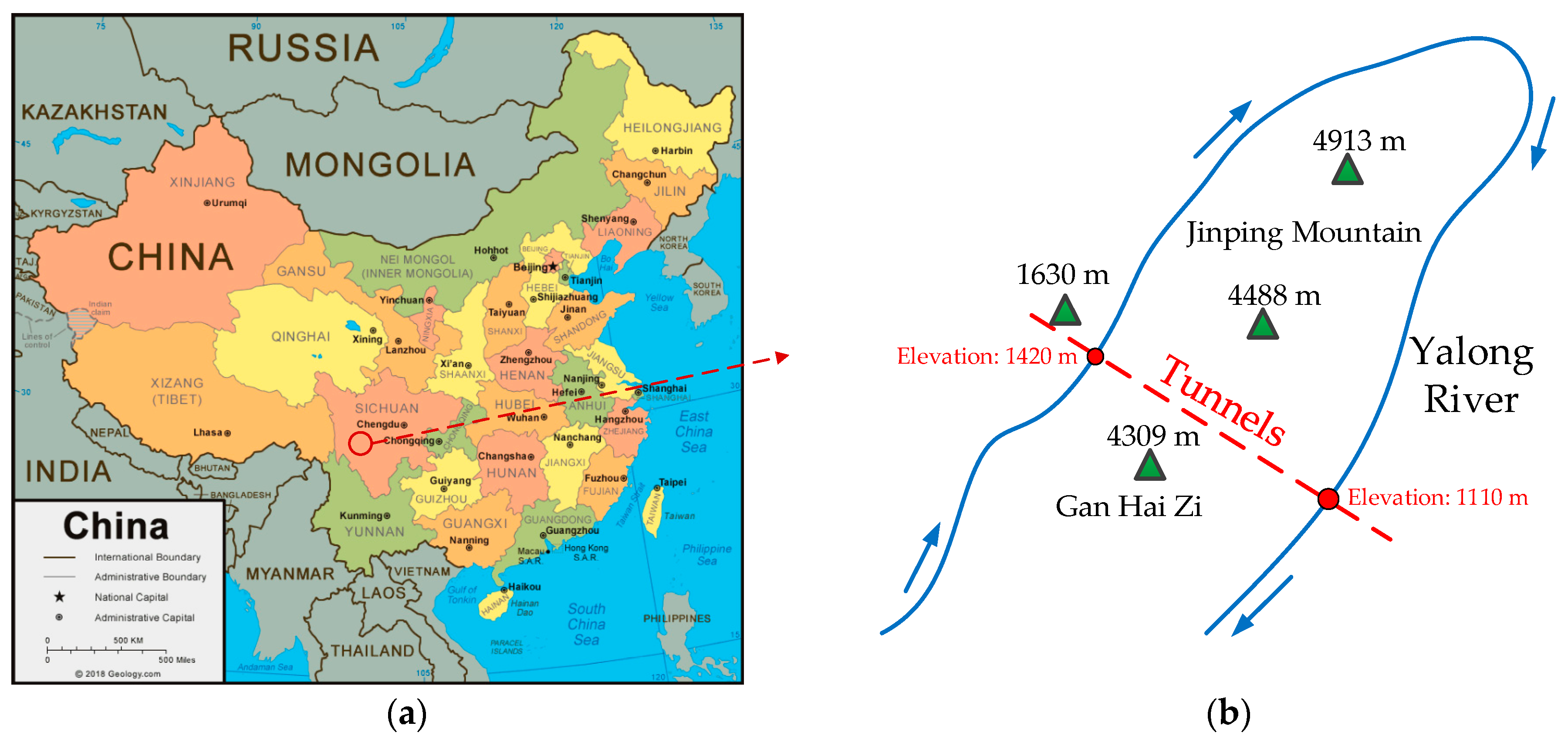
2. Project Overview
2.1. Geological Conditions
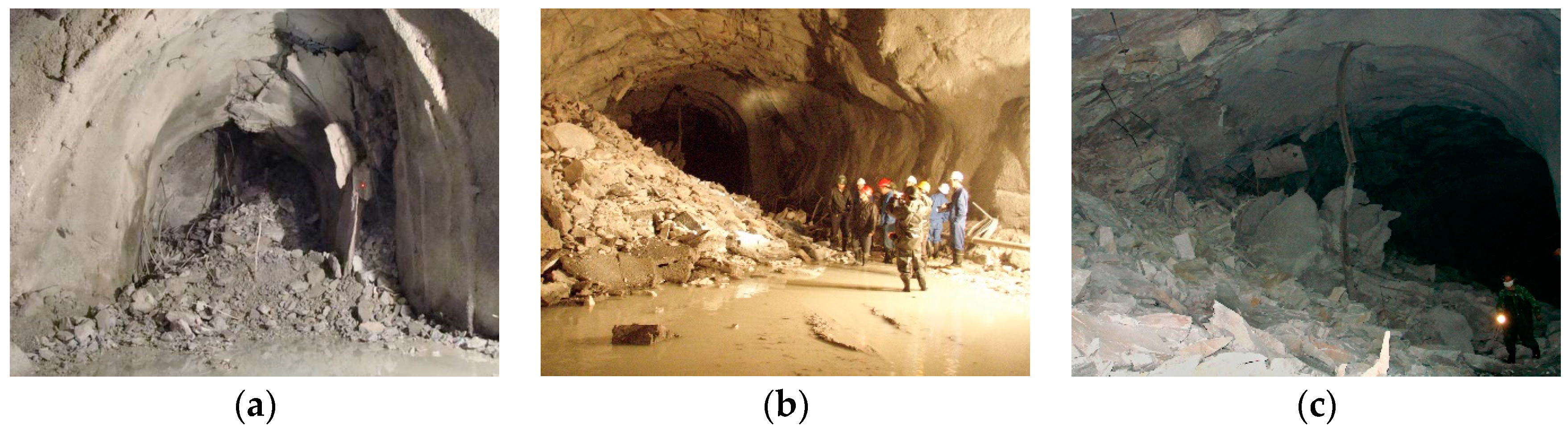
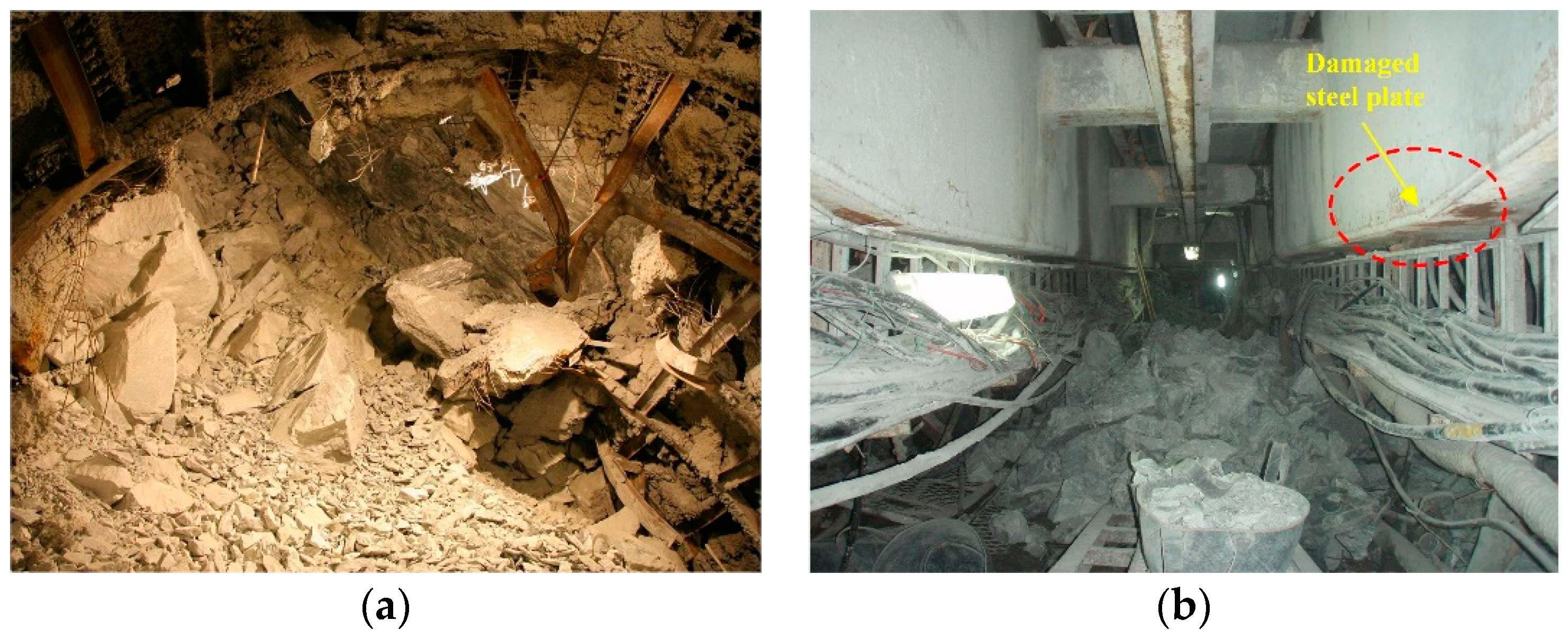
2.2. Rockburst in Tunnels
3. Numerical Simulation
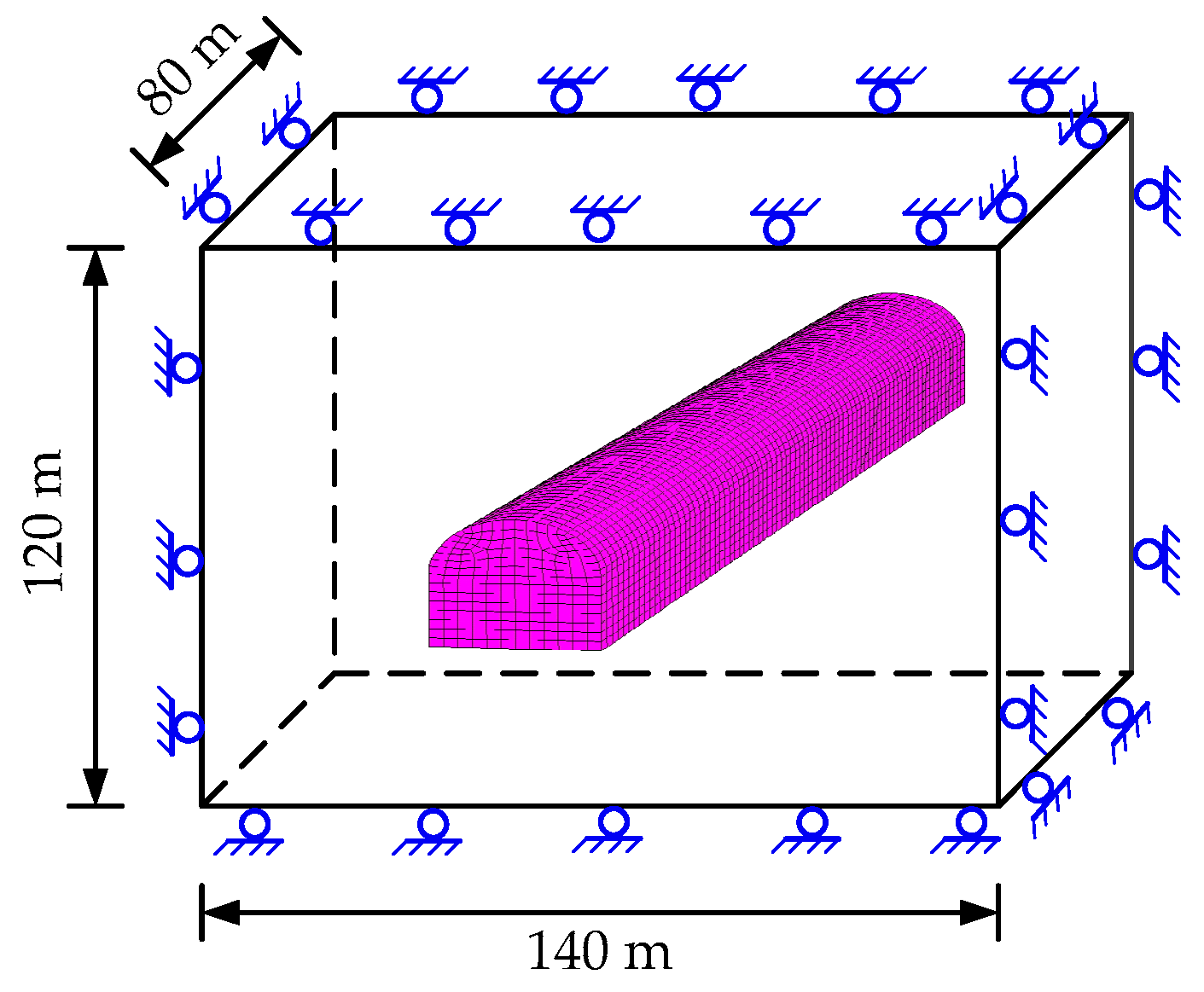
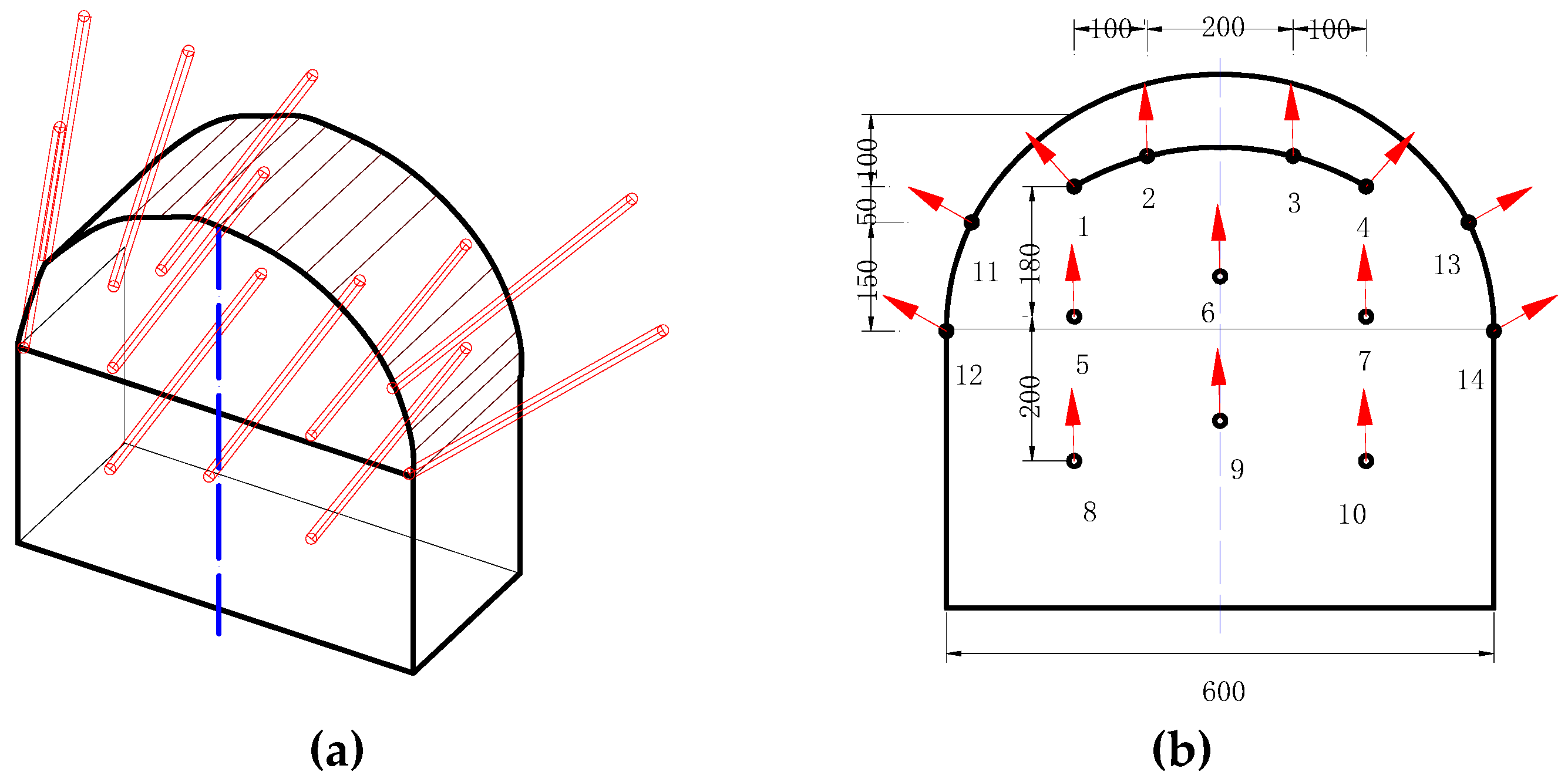
3.1. Model Description
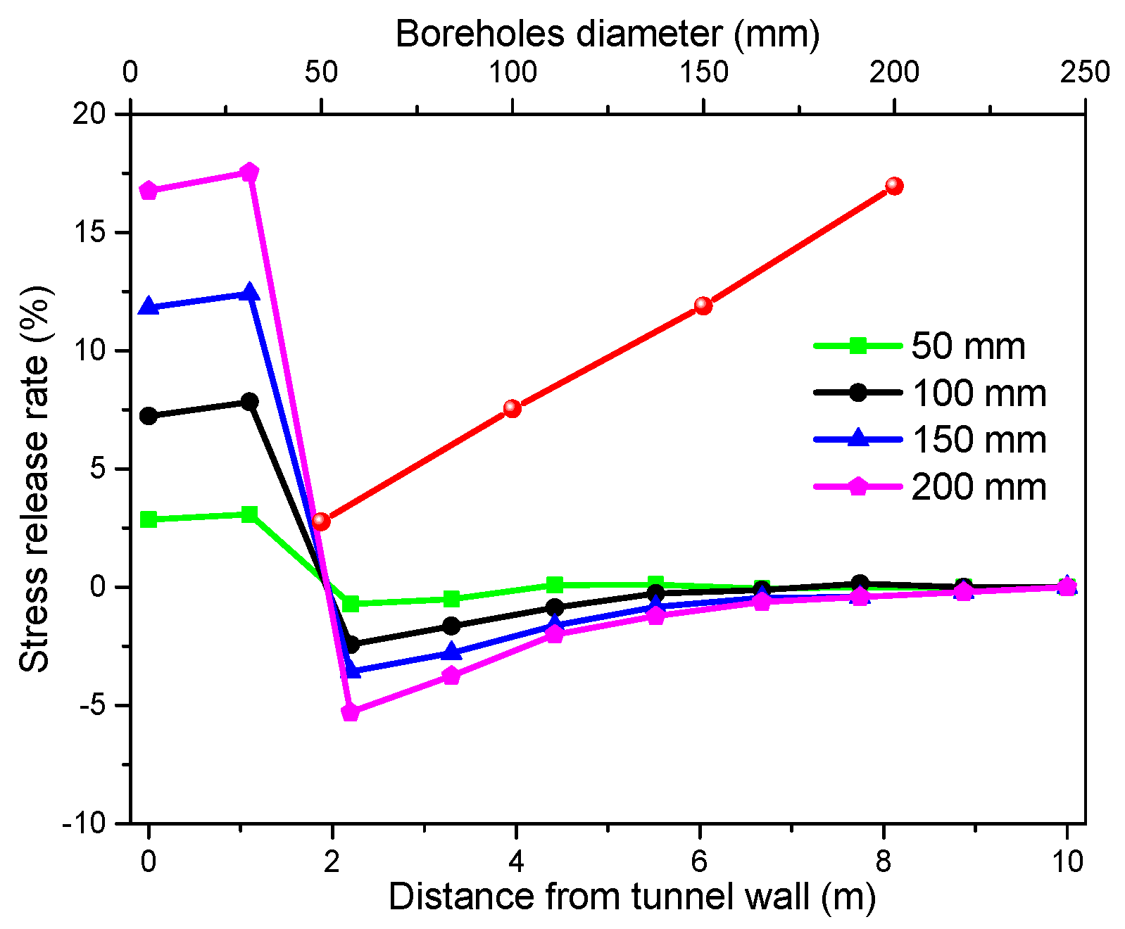
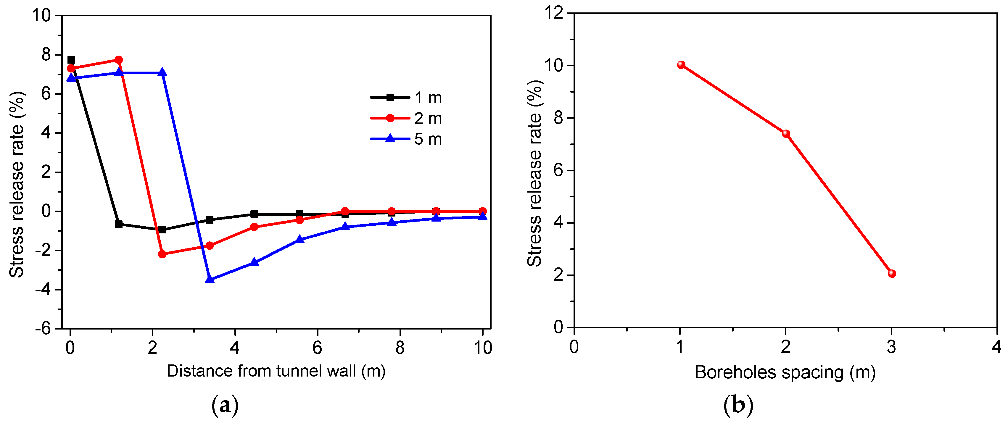
3.2. Stress Release Hole
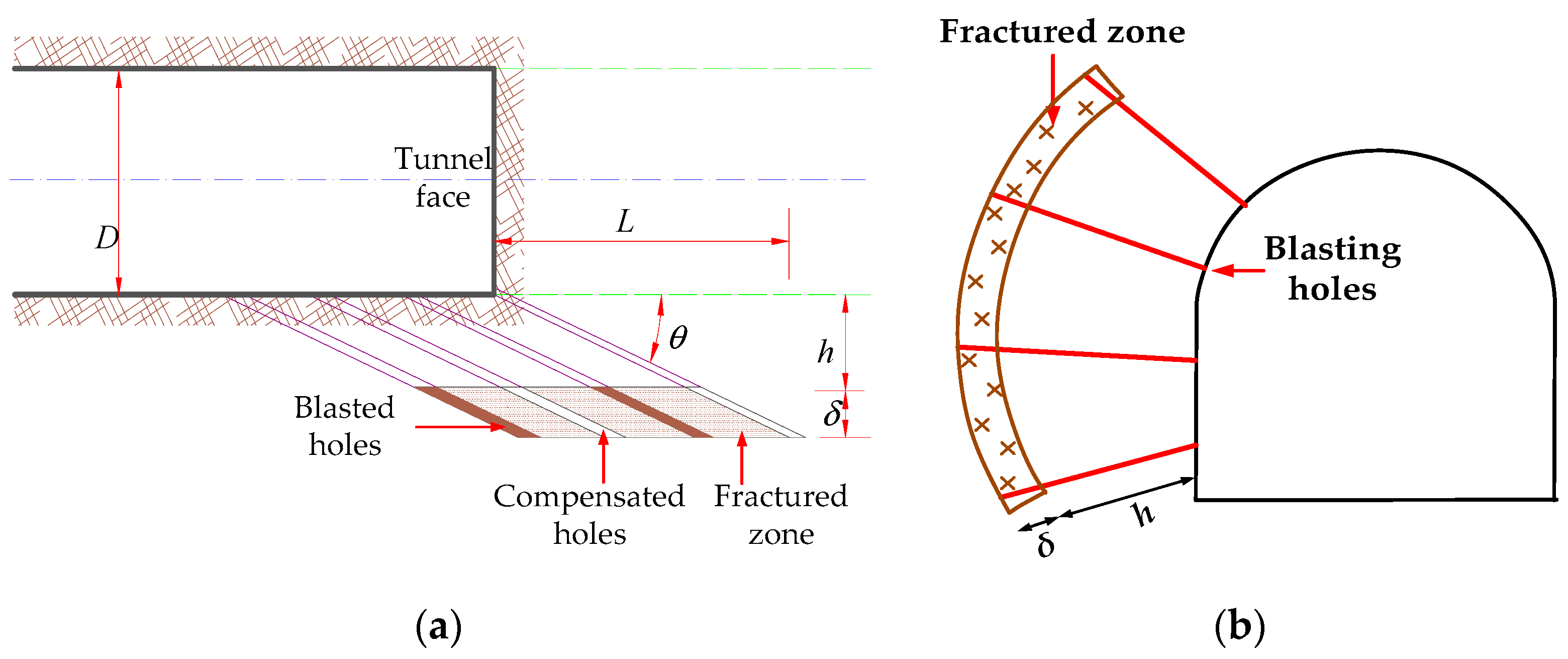
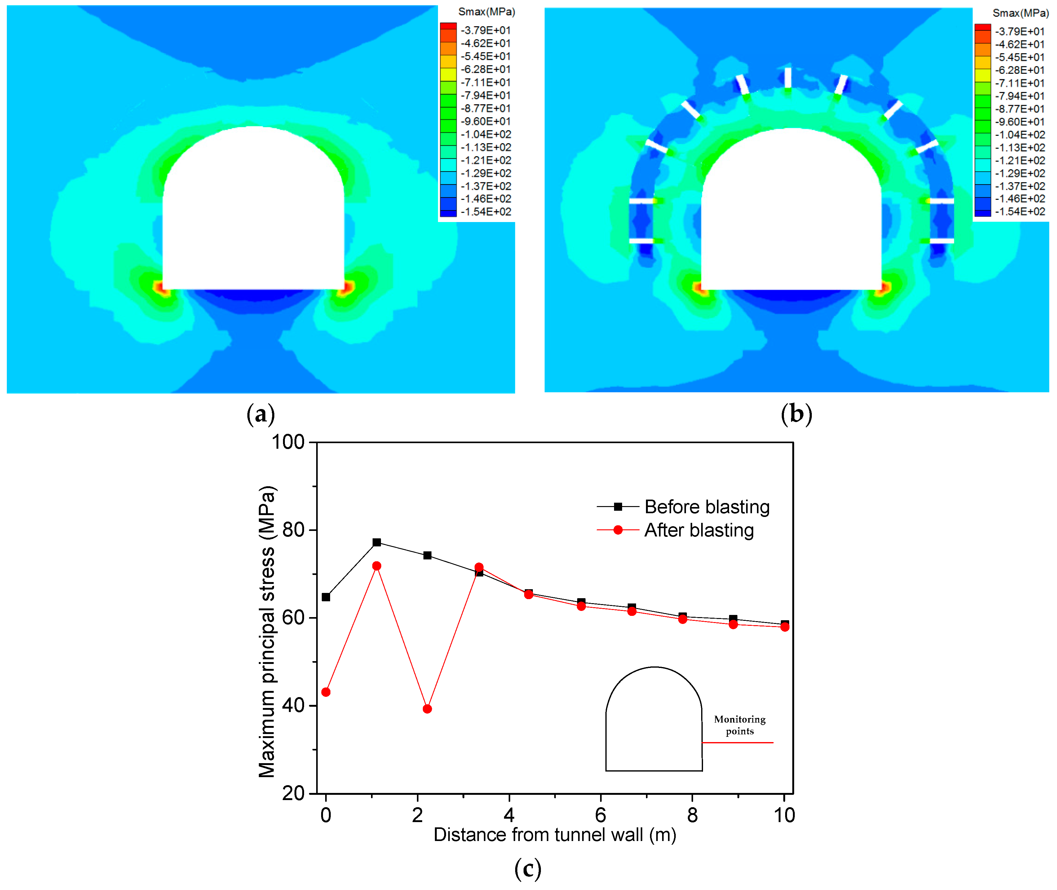
3.3. Advanced Stress Relief Blasting
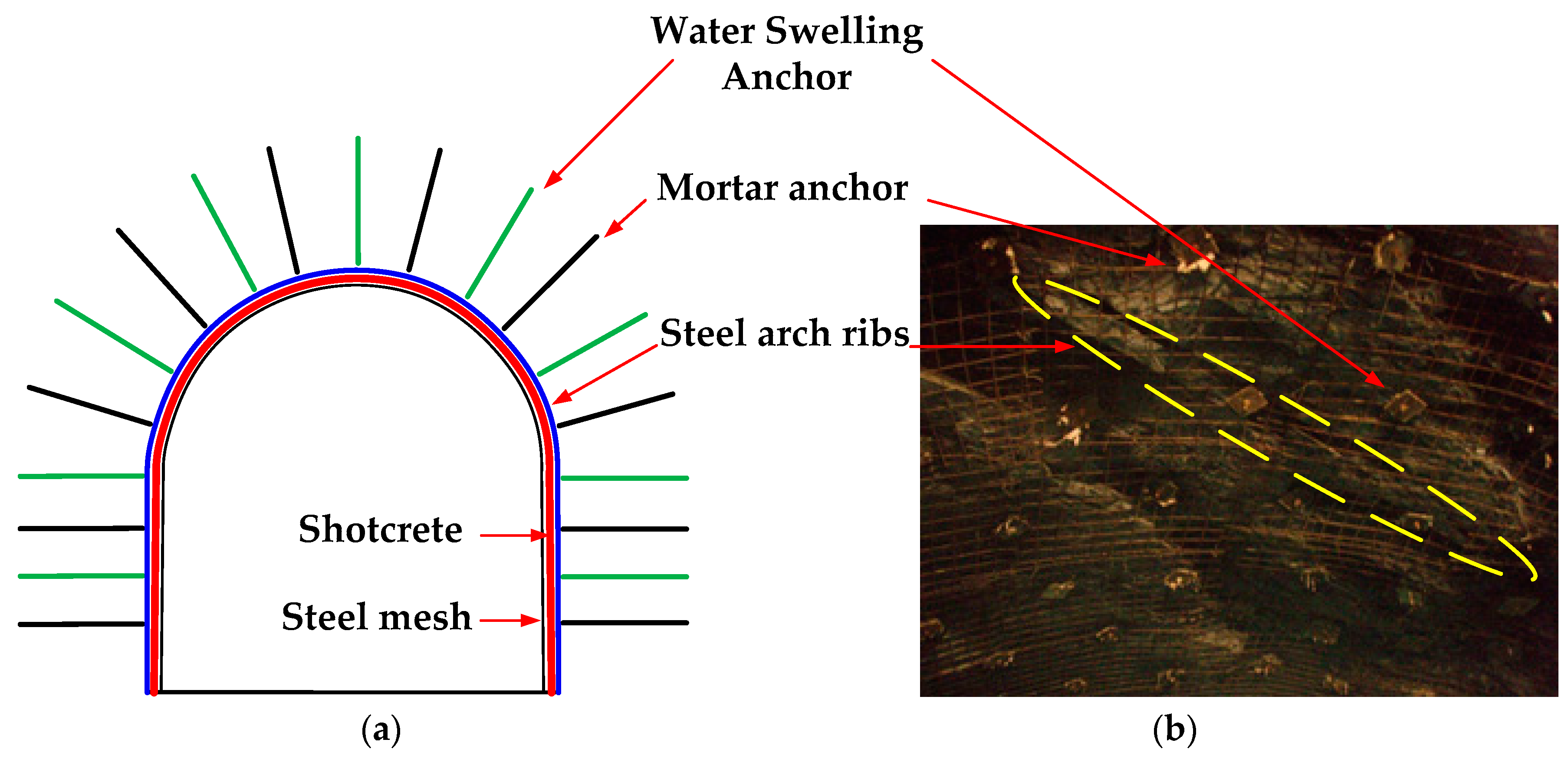
3.4. Rapid Combined Support
3.4.1. Water Swelling Anchor
3.4.2. Nano-Admixture Shotcrete
4. Field Application of Research Results
5. Conclusions
Author Contributions
Funding
Acknowledgments
Conflicts of Interest
References
- Zhang, H.; Chen, L.; Zhu, Y.; Zhou, Z.; Chen, S. Stress Field Distribution and Deformation Law of Large Deformation Tunnel Excavation in Soft Rock Mass. Appl. Sci. 2019, 9, 865. [Google Scholar] [CrossRef]
- Zhang, Z.Q.; Zhang, H.; Tan, Y.J.; Yang, H.Y. Natural wind utilization in the vertical shaft of a super-long highway tunnel and its energy saving effect. Build. Environ. 2018, 145, 140–152. [Google Scholar] [CrossRef]
- Zhu, Y.; Chen, L.; Zhang, H.; Zhou, Z.; Chen, S. Physical and Mechanical Characteristics of Soft Rock Tunnel and the Effect of Excavation on Supporting Structure. Appl. Sci. 2019, 9, 1517. [Google Scholar] [CrossRef]
- Tang, F.; Li, L.J.; Dong, M.S.; Wang, Q.; Mei, F.Z.; Hu, L.H. Characterization of buoyant flow stratification behaviors by Richardson (Froude) number in a tunnel fire with complex combination of longitudinal ventilation and ceiling extraction. Appl. Therm. Eng. 2017, 110, 1021–1028. [Google Scholar] [CrossRef]
- Kaiser, P.K.; Cai, M. Design of rock support system under rockburst condition. J. Rock Mech. Geotech. Eng. 2012, 4, 215–227. [Google Scholar] [CrossRef]
- Mei, F.Z.; Tang, F.; Ling, X.; Yu, J.S. Evolution characteristics of fire smoke layer thickness in a mechanical ventilation tunnel with multiple point extraction. Appl. Therm. Eng. 2017, 111, 248–256. [Google Scholar] [CrossRef]
- Wang, F.; Wang, M.N.; Huo, J.X. The effects of the passive fire protection layer on the behavior of concrete tunnel linings: A field fire testing study. Tunn. Underg. Sp. Tech. 2017, 69, 162–170. [Google Scholar] [CrossRef]
- Tang, F.; Cao, Z.L.; Adriana, P.; Wang, Q. A study on the maximum temperature of ceiling jet induced by rectangular-source fires in a tunnel using ceiling smoke extraction. Int. J. Therm. Sci. 2018, 127, 329–334. [Google Scholar] [CrossRef]
- Wang, F.; Wang, M.N.; Ricky, C.; Wang, Y. Numerical study on fire smoke movement and control in curved road tunnels. Tunn. Underg. Sp. Tech. 2017, 67, 1–7. [Google Scholar] [CrossRef]
- Wang, F.; Wang, M.N. A computational study on effects of fire location on smoke movement in a road tunnel. Tunn. Underg. Sp. Tech. 2016, 51, 405–413. [Google Scholar] [CrossRef]
- Zhang, Z.; Li, H.; Yang, H.; Wang, B. Failure modes and face instability of shallow tunnels under soft grounds. Int. J. Damage Mech. 2019, 28, 566–589. [Google Scholar] [CrossRef]
- Wang, F.; Luo, F.Y.; Huang, Y.B.; Zhu, L.; Hu, H. Thermal analysis and air temperature prediction in TBM construction tunnels. Appl. Therm. Eng. 2019, 158, 113822. [Google Scholar] [CrossRef]
- Basson, F.R.P.; Van Der Merwe, S. Seismicity Management as Hill 50 Gold Mine, Western Australia. In Proceedings of the Fourth International Seminar on Deep and High Stress Mining, Perth, Australia, 7–9 November 2007; Australian Centre for Geomechanics: Crawley, Perth, WA, Australia, 2007; pp. 233–242. [Google Scholar]
- Urbancic, T.I.; Trifu, C.I. Recent advances in seismic monitoring technology at Canadian mines. J. Appl. Geophys. 2000, 45, 225–237. [Google Scholar] [CrossRef]
- Durrheim, R.J.; Haile, A.; Roberts, M.K.C.; Schweitzer, J.K.; Spottiswoode, S.M.; Klokow, J.W. Violent failure of a remnant in a deep South African gold mine. Tectonophysics 1998, 289, 105–116. [Google Scholar] [CrossRef]
- Milev, A.M.; Spottiswoode, S.M.; Rorke, A.J.; Finnie, G.J. Seismic monitoring of a simulated rockburst on a wall of an underground tunnel. J. S. Afr. Inst. Min. Metall. 2001, 101, 253–260. [Google Scholar]
- Feng, X.T.; Yang, Y.; Feng, G.L.; Xiao, Y.X.; Chen, B.R.; Jiang, Q. Fractal behaviour of the microseismic energy associated with immediate rockbursts in deep, hard rock tunnels. Tunn. Undergr. Space Technol. 2016, 51, 98–107. [Google Scholar] [CrossRef]
- Zhang, H.; Chen, L.; Chen, S.G.; Sun, J.C.; Yang, J.S. The spatiotemporal distribution law of microseismic events and rockburst characteristics of the deeply buried tunnel group. Energies 2018, 11, 3257. [Google Scholar] [CrossRef]
- Zhang, Z.Q.; Shi, X.Q.; Wang, B.; Li, H.Y. Stability of NATM tunnel faces in soft surrounding rocks. Comput. Geotech. 2018, 96, 90–102. [Google Scholar] [CrossRef]
- Blake, W.; Hedley, D.G.F. Rockbursts, Case Studies from North American Hardrock Mines; Society for Mining, Metallurgy, and Exploration: Littleton, CO, USA, 2003. [Google Scholar]
- Ortlepp, W.D.; Stacey, T.R. Rockburst mechanisms in tunnels and shafts. Tunn. Undergr. Space Technol. 1994, 9, 59–65. [Google Scholar] [CrossRef]
- Martin, C.D.; Kaiser, P.K.; McCreath, D.R. Hoek-Brown parameters for predicting the depth of brittle failure around tunnels. Can. Geotech. J. 1999, 36, 136–151. [Google Scholar] [CrossRef]
- Beck, D.A.; Brady, B.H.G. Evaluation and application of controlling parameters for seismic events in hard–rock mines. Int. J. Rock Mech. Min. Sci. 2002, 39, 633–642. [Google Scholar] [CrossRef]
- Li, T.B.; Ma, C.C.; Zhu, M.L.; Meng, L.B.; Chen, G.Q. Geomechanical types and mechanical analyses of rockbursts. Eng. Geol. 2017, 222, 72–83. [Google Scholar] [CrossRef]
- Hatzor, Y.H.; He, B.G.; Feng, X.T. Scaling rockburst hazard using the DDA and GSI methods. Tunn. Undergr. Space Technol. 2017, 70, 343–362. [Google Scholar] [CrossRef]
- Chen, B.R.; Feng, X.T.; Li, Q.P.; Luo, R.Z.; Li, S.J. Rock burst intensity classification based on the radiated energy with damage intensity at Jinping II hydropower station, China. Rock Mech. Rock Eng. 2015, 48, 289–303. [Google Scholar] [CrossRef]
- Ma, K.; Tang, C.A.; Wang, L.X.; Tang, D.H.; Zhuang, D.Y.; Zhang, Q.B.; Zhao, J. Stability analysis of underground oil storage caverns by an integrated numerical and microseismic monitoring approach. Tunn. Undergr. Space Technol. 2016, 54, 81–91. [Google Scholar] [CrossRef]
- Xie, H.; Pariseau, W.G. Fractal character and mechanism of rock bursts. Int. J. Rock Mech. Min. Sci. 1993, 30, 343–350. [Google Scholar] [CrossRef]
- Gong, Q.M.; Yin, L.J.; Wu, S.Y.; Zhao, J.; Ting, Y. Rock burst and slabbing failure and its influence on TBM excavation at headrace tunnels in Jinping II hydropower station. Eng. Geol. 2012, 124, 98–108. [Google Scholar] [CrossRef]
- He, M.C.; Sousa, L.R.; Miranda, T.; Zhu, G.L. Rockburst laboratory tests database—Application of data mining techniques. Eng. Geol. 2015, 185, 116–130. [Google Scholar] [CrossRef]
- Müller, W. Numerical simulation of rock bursts. Min. Sci. Technol. 1991, 12, 27–42. [Google Scholar] [CrossRef]
- Hedley, D.G.F. Rockburst Handbook for Ontario Hardrock Mines; Canada Centre for Mineral and Energy Technology, Mining Research Laboratories (CANMET): Ottawa, ON, Canada, 1992. [Google Scholar]
- Kaiser, P.K.; MacCreath, D.R.; Tannant, D.D. Canadian Rockburst Support Handbook: Prepared for Sponsors of the Canadian Rockburst Research Program 1990–1995; Geomechanics Research Centre: Sudbury, ON, Canada, 1996. [Google Scholar]
- Stacey, T.R. Dynamic rock failure and its containment—A Gordian knot design problem. In Proceedings of the First International Conference on Rock Dynamics and Applications (RocDyn 1), Lausanne, Switzerland, 6–8 June 2013; Swit State of the Art. CRC Press: Balkema, Switzerland, 2013. [Google Scholar]
- Linkov, A.V. Dynamic Phenomena in Mines and the Problem of Stability. Ph.D. Thesis, University of Minnesota, Minneapolis, MN, USA, 1992. [Google Scholar]
- Yang, C.X.; Luo, Z.Q.; Hu, G.B.; Liu, X.M. Application of a microseismic monitoring system in deep mining. J. Univ. Sci. Technol. Beijing 2007, 14, 6–8. [Google Scholar] [CrossRef]
- Wang, J.M.; Zeng, X.H.; Zhou, J.F. Practices on rockburst prevention and control in headrace tunnels of Jinping II hydropower station. J. Rock Mech. Geotech. Eng. 2012, 4, 258–268. [Google Scholar] [CrossRef]
- Wang, H.L.; Ge, M.C. Acoustic emission/microseismic source location analysis for a limestone mine exhibiting high horizontal stresses. Int. J. Rock Mech. Min. Sci. 2008, 45, 720–728. [Google Scholar] [CrossRef]
- Afraei, S.; Shahriar, K.; Madani, S.H. Developing intelligent classification models for rock burst prediction after recognizing significant predictor variables, Section 1: Literature review and data preprocessing procedure. Tunn. Undergr. Space Technol. 2019, 83, 324–353. [Google Scholar] [CrossRef]
- Cai, W.; Dou, L.M.; Zhang, M.; Cao, W.Z.; Shi, J.Q.; Feng, L.F. A fuzzy comprehensive evaluation methodology for rock burst forecasting using microseismic monitoring. Tunn. Undergr. Space Technol. 2018, 80, 232–245. [Google Scholar] [CrossRef]
- Xu, J.; Jiang, J.D.; Xu, N.; Liu, Q.S.; Gao, Y.F. A new energy index for evaluating the tendency of rockburst and its engineering application. Eng. Geol. 2017, 230, 46–54. [Google Scholar] [CrossRef]
- Srinivasan, C.; Arora, S.K.; Benady, S. Precursory monitoring of impending rockbursts in Kolar gold mines from microseismic emissions at deeper levels. Int. J. Rock Mech. Min. Sci. 1999, 36, 941–948. [Google Scholar] [CrossRef]
- Li, S.J.; Feng, X.T.; Li, Z.H.; Chen, B.R.; Zhang, C.Q.; Zhou, H. In situ monitoring of rockburst nucleation and evolution in the deeply buried tunnels of Jinping II hydropower station. Eng. Geol. 2012, 137, 85–96. [Google Scholar] [CrossRef]
- Huang, R.Q.; Wang, X.N. Analysis of dynamic disturbance on rock burst. Bull. Eng. Geol. Environ. 1999, 57, 281–284. [Google Scholar] [CrossRef]
- Amin, M.; Ming, C. Numerical modeling of rockburst near fault zones in deep tunnels. Tunn. Undergr. Space Technol. 2018, 80, 164–180. [Google Scholar]
- Li, X.; Li, X.F.; Zhang, Q.B.; Zhao, J. A numerical study of spalling and related rockburst under dynamic disturbance using a particle-based numerical manifold method (PNMM). Tunn. Undergr. Space Technol. 2018, 81, 438–449. [Google Scholar] [CrossRef]
- Weng, L.; Huang, L.Q.; Taheri, A.; Li, X.B. Rockburst characteristics and numerical simulation based on a strain energy density index: A case study of a roadway in Linglong gold mine, China. Tunn. Undergr. Space Technol. 2017, 69, 223–232. [Google Scholar] [CrossRef]
- Hu, L.H.; Ma, K.; Liang, X.; Tang, C.; Wang, Z.W.; Yan, L.B. Experimental and numerical study on rockburst triggered by tangential weak cyclic dynamic disturbance under true triaxial conditions. Tunn. Undergr. Space Technol. 2018, 81, 602–618. [Google Scholar] [CrossRef]
- Zhu, W.C.; Li, Z.H.; Zhu, L.; Tang, C.A. Numerical simulation on rockburst of underground opening triggered by dynamic disturbance. Tunn. Undergr. Space Technol. 2010, 25, 587–599. [Google Scholar] [CrossRef]
- Jiang, Q.; Feng, X.T.; Xiang, T.B.; Su, G.S. Rockburst characteristics and numerical simulation based on a new energy index: A case study of a tunnel at 2,500 m depth. Bull. Eng. Geol. Environ. 2010, 69, 381–388. [Google Scholar] [CrossRef]
- Dou, L.; Lu, C.; Mu, Z.; Gao, M.S. Prevention and forecasting of rock burst hazards in coal mines. Min. Sci. Technol. 2009, 19, 585–591. [Google Scholar] [CrossRef]
- He, H.; Dou, L.M.; Gong, S.Y.; Wang, L.L.; Gao, M.S.; Zhang, X.F. Mechanism of rockburst prevention and supporting control technology in roadways. J. Min. Saf. Eng. 2010, 1, 40–44. [Google Scholar]


| Density ρ (kg/m3) | Poisson Ratio μ | Internal Friction Angle φ (°) | Cohesion C (MPa) | Elasticity Modulus E (GPa) | Lateral Pressure Coefficient |
|---|---|---|---|---|---|
| 2840 | 0.25 | 45 | 7.5 | 80 | 0.8 |
| Conditions Number | Boreholes Diameter (mm) | Boreholes Length (m) | Boreholes Spacing (m) |
|---|---|---|---|
| 1 | 50 | 2 | 2 |
| 2 | 100 | 2 | 2 |
| 3 | 150 | 2 | 2 |
| 4 | 200 | 2 | 2 |
| 5 | 100 | 1 | 2 |
| 6 | 100 | 3 | 2 |
| 7 | 100 | 2 | 1 |
| 8 | 100 | 2 | 3 |
| Density (kg/m3) | Diameter (mm) | Elasticity Modulus (GPa) | The Tensile/Pressure Strength (tons) | Length (m) | Spacing (m) |
|---|---|---|---|---|---|
| 7500 | 22 | 210 | 25 | 3.0 | 2.0 |
| Density (kg/m3) | Thickness (m) | Elasticity Modulus (GPa) | The Tensile/Pressure Strength (MPa) | Residual Tensile Strength (MPa) | Poisson Ratio |
|---|---|---|---|---|---|
| 2500 | 0.05–1.5 | 21 | 3.0/30.0 | 1.0 | 0.15 |
© 2019 by the authors. Licensee MDPI, Basel, Switzerland. This article is an open access article distributed under the terms and conditions of the Creative Commons Attribution (CC BY) license (http://creativecommons.org/licenses/by/4.0/).
Share and Cite
Zhang, H.; Zhu, Y.; Chen, L.; Hu, W.; Chen, S. The Prevention and Control Mechanism of Rockburst Hazards and Its Application in the Construction of a Deeply Buried Tunnel. Appl. Sci. 2019, 9, 3629. https://doi.org/10.3390/app9173629
Zhang H, Zhu Y, Chen L, Hu W, Chen S. The Prevention and Control Mechanism of Rockburst Hazards and Its Application in the Construction of a Deeply Buried Tunnel. Applied Sciences. 2019; 9(17):3629. https://doi.org/10.3390/app9173629
Chicago/Turabian StyleZhang, Heng, Yimo Zhu, Liang Chen, Weidong Hu, and Shougen Chen. 2019. "The Prevention and Control Mechanism of Rockburst Hazards and Its Application in the Construction of a Deeply Buried Tunnel" Applied Sciences 9, no. 17: 3629. https://doi.org/10.3390/app9173629
APA StyleZhang, H., Zhu, Y., Chen, L., Hu, W., & Chen, S. (2019). The Prevention and Control Mechanism of Rockburst Hazards and Its Application in the Construction of a Deeply Buried Tunnel. Applied Sciences, 9(17), 3629. https://doi.org/10.3390/app9173629