Article

Performance Assessment of Grid Forming Converters Using Different Finite Control Set Model Predictive Control (FCS-MPC) Algorithms

by
Mohammed Alhasheem
1,2,*,†,
Frede Blaabjerg
1,† and
Pooya Davari
1,†
1
Department of Energy Technology, Aalborg University, 9220 Aalborg, Denmark
2
Arab Academy for Science, Technology and Maritime Transport, Cairo 2033, Egypt
*
Author to whom correspondence should be addressed.
Current address: Pontoppidanstraede 111, DK-9220 Aalborg East, Denmark.
Appl. Sci. 2019, 9(17), 3513; https://doi.org/10.3390/app9173513
Submission received: 15 July 2019 / Revised: 15 August 2019 / Accepted: 22 August 2019 / Published: 26 August 2019
(This article belongs to the Special Issue Power Electronic Applications in Power and Energy Systems)

Abstract

:
Finite control set model predictive control (FCS-MPC) methods in different power electronic applications are gaining considerable attention due to their simplicity and fast dynamics. This paper introduces an assessment of the two-level three-phase voltage source converter (2L-VSC) utilizing different MPC schemes with and without a modulation stage. In order to perform such a comparative evaluation, 2L-VSC efficiency and total harmonics distortion of the voltage (THDv) have been investigated, when considering a linear load. The results demonstrate the performance of different MPC algorithms through an experimental verification on a Danfoss converter, and a set of analyses have been studied using the PLECS and MATLAB/SIMULINK together. It can be concluded that a comparable performance is achieved by using conventional MPC (CMPC), improved MPC (IMPC), periodic MPC (PMPC), and MPC scheme with modulator (M 2 PC) controllers. The assessment is critical to classify the strategies as mentioned earlier according to their efficiency. Furthermore, it gives a thorough point of view on which algorithm is suitable for the grid-forming applications.

1. Introduction

In recent years, model predictive control has become a well-established control strategy, mainly due to its fast dynamic response, simplicity, and the ability to include constraints and nonlinearities in the controller design. Recently, predictive current and voltage control are the most popular case studies, where the predictions are carried out for each possible switching state to determine the proper actions. The decision is made through an optimization process evaluated by the cost function (CF) [1,2,3,4,5,6,7].
The finite control set model predictive control (FCS-MPC) strategy provides a variable switching frequency due to the absence of the modulator. Therefore, noise and high voltage or current ripples are generated [8]. This noise leads to a spread spectrum, which decreases the overall performance of the system in terms of power quality [9,10]. A large amount of research and investigations have been devoted to solving the variable switching frequency issue while maintaining the FCS-MPC characteristics and even improving them. Prior-art methods are aimed at embedding the modulator, and others intended to use the benefit of adding another objective in the CF to either control the switching frequency or make it fixed. For instance, the introduced method in [11] is based on including a suitable modulation scheme in the cost function minimization criterion of the predictive algorithm for a selected number of switching states. In [12], the authors proposed a new technique, periodic control based FCS-MPC, to solve the variable switching frequency issue, and uncharacteristic switching pattern without the need for a modulator.
On the other hand, FCS-MPC can provide a better power quality if either the modulator or the periodic control based are not applied. The lack of the switching frequency regulation leaves an upper limit up to half of the sampling frequency, and that may lead to undesired losses in the semiconductors. Furthermore, the switching variations may be high or low based on the operation point and the system parameters.
In this work, four model predictive algorithms will be assessed. In [13], a conventional FCS-MPC is proposed for grid forming converters in microgrids (MGs) applications. The proposed MPC is evaluating for a single objective, and no respect is given to the switching frequency regulation. In [14], an improvement of the traditional FCS-MPC presented in [13] has been proposed to provide better power quality. Both algorithms have been assessed up to 4 kW in terms of power quality and losses in [15]. Apparently, there is a lack of information on how both algorithms are classified comparing to the regulated MPC algorithms. Thus, the modulated predictive algorithms in [11,12] will be analyzed and examined, in this work, with the algorithms in [13,14].
In order to perform the assessment, a three-phase voltage source converter (VSC) has been used, as shown in Figure 1. The simulation study has been performed by developing a loss model using a PLECS circuit to make a preliminary investigation and obtain the losses distribution in each strategy [16,17]. The purpose of this paper is not only to show how the selected MPC algorithms are influencing the converter efficiency, but also to highlight their preferences. Hence, in this paper, a comprehensive overview of the total harmonics distortion of the voltage (THDv) and efficiency using the discussed MPC techniques is presented. The rest of the article is organized as follows; the converter model is described in Section 2. In Section 3, the selected MPC algorithms are explained in detail. In Section 4, power loss calculations are presented. In Section 5, the obtained results and remarks are given. A proposal for standardized switching frequency is provided in Section 6. Finally, the summary of the work is given in Section 7.

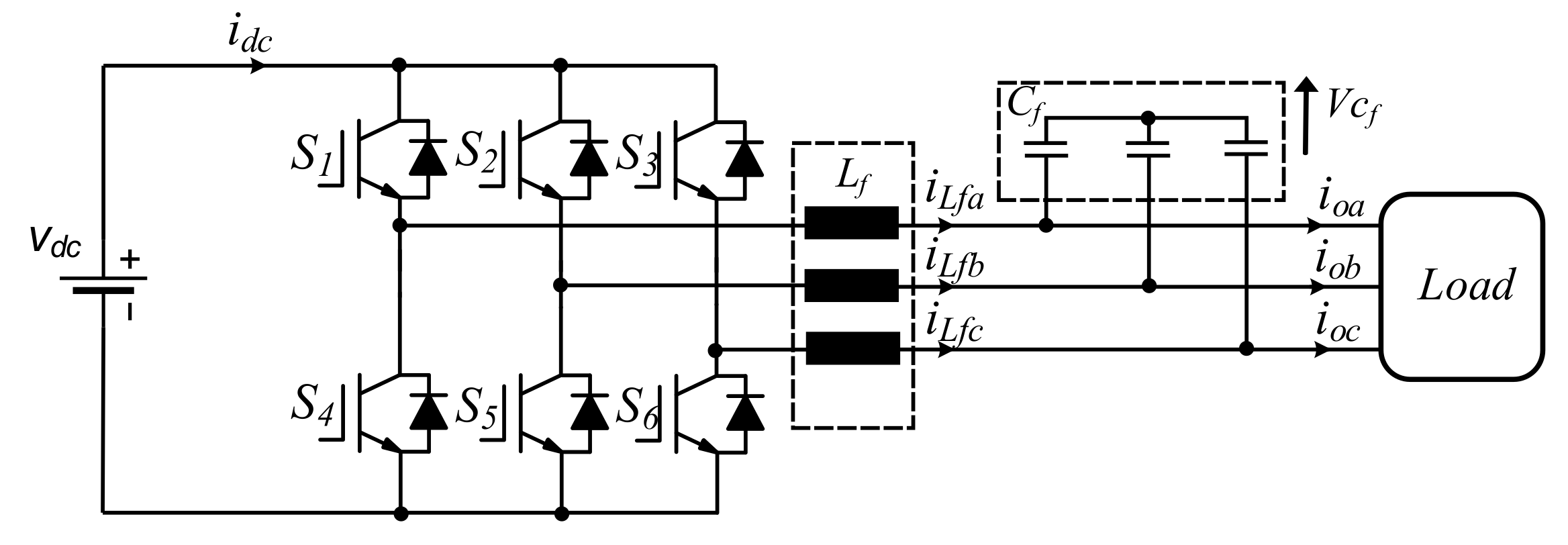
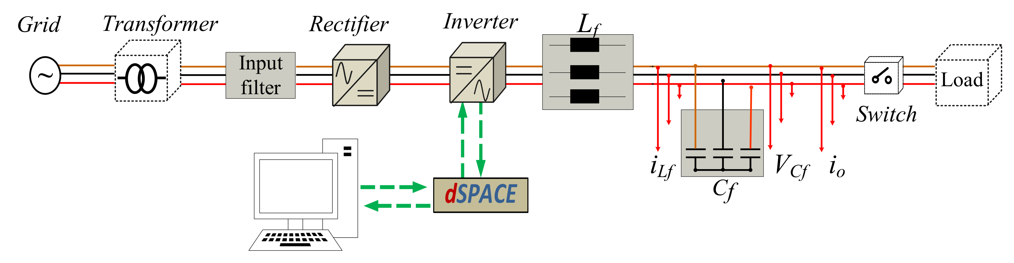
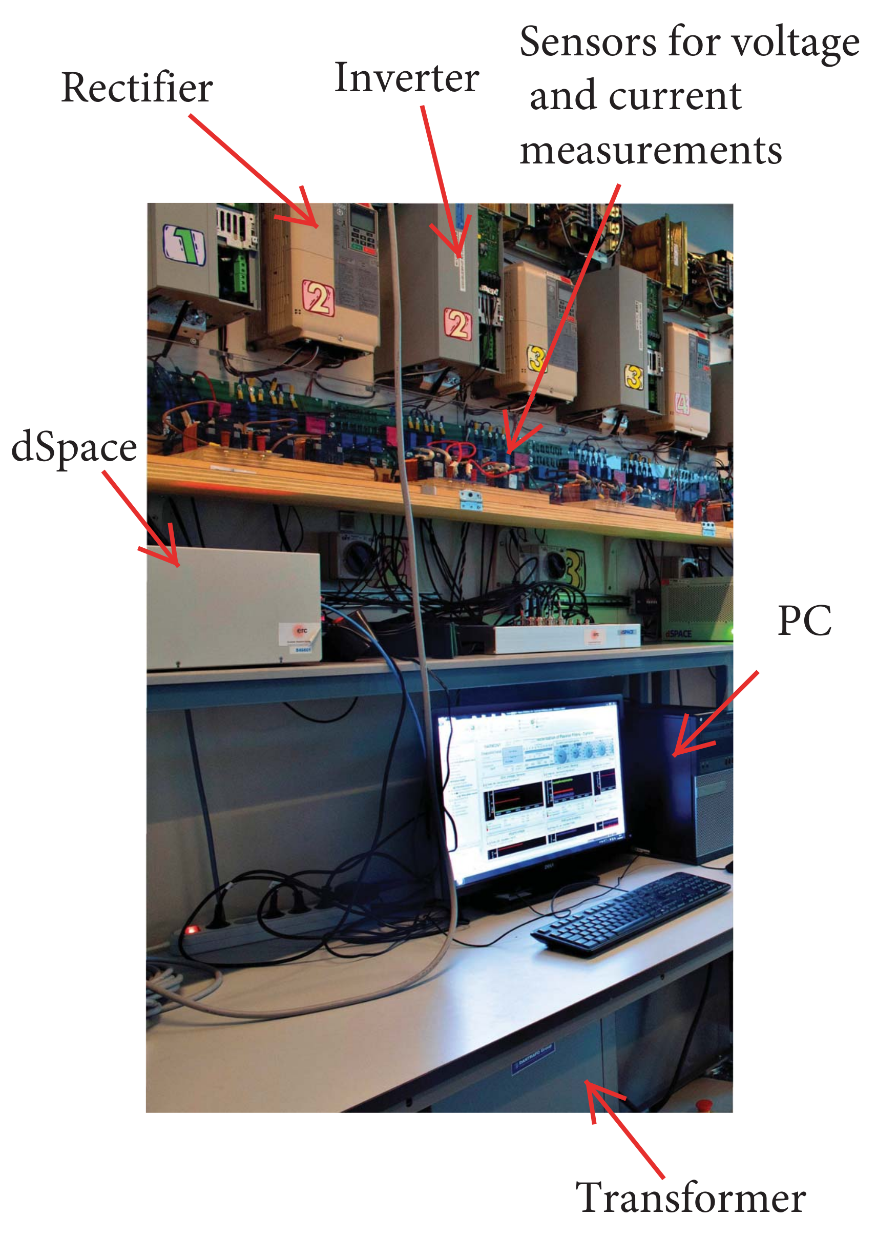
2. Systems Description

Converter Model

The power circuit of the three phase two-level voltage source converter (2L-VSC), is considered, where the two switches in each leg operate in a complementary mode. The switching states can be represented by the switching signals S k a , S k b , and S k c , which are defined as follows:
S k a = 1   i f   S 1   o n   a n d   S 4   o f f 0   i f   S 1   o f f   a n d   S 4   o n
S k b = 1   i f   S 2   o n   a n d   S 5   o f f 0   i f   S 2   o f f   a n d   S 5   o n
S k c = 1   i f   S 3   o n   a n d   S 6   o f f 0   i f   S 3   o f f   a n d   S 6   o n
The filter inductance ( L f a , L f b , L f c ) equation can be expressed in the vectorial form as:
L f d i L f d t = V i V c f
where L f is the filter inductance. The equation that describes the dynamic behaviour of the output voltage can be expressed mathematically as:
C f d V c f d t = i L f i o
where C f is the filter capacitance ( C f a , C f b , C f c ). These equations can be rewritten in the state space model as:
d X d t = A X + B 1 V i + B 2 i o
where,
X = i L f V c f
A = R / L f 1 / L f 1 / C f 0
B 1 = 1 / L f 0
B 2 = 0 1 / C f
where i L f and V c f are the filter current and voltage respectively. i o is the load current, which can be estimated or measured. V i is the inverter voltage of the system and it has eight different voltage vectors as shown in Figure 2.
A discrete model is obtained from (6) and it can be expressed as follows:
x k + 1 = A q x k + B q V i k + B d q i o k
where,
A q = e x p A T s
B q = 0 T s e x p A τ B 1 d τ
B d q = 0 T s e x p A τ B 2 d τ .
This model is used to calculate the prediction of filter voltages and currents for every possible input voltage. The selection of the optimal input voltage depends on the evaluation of CF [18]. Consequently, the new switching states are applied to the converter for the next sampling time.

3. Selected MPC Algorithms

3.1. Conventional Model Predictive Control Algorithm (CMPC)

The conventional FCS-MPC algorithm is formulated in the discrete-time domain. A prediction horizon N = 1 based on the accurate system model is used to predict the future value of the state variable (V) and feed the measurements back at the Kt instant, as shown in Figure 3a. In this scenario, a single objective CF, which is described mathematically in (15), defines the control system objective. In fact, the state variable V moves toward the reference trajectory V * and is defined as V p . Finally, new measurements, new predictions, and performance optimization of the CF are repeated during each sampling interval [3].
g = ( V c f α * V c f α p ( k + 1 ) ) 2 + ( V c f β * V c f β p ( k + 1 ) ) 2

3.2. Improved Model Predictive Control Algorithm (IMPC)

Using the conventional CF in (15) results in satisfactory performance in the case of the first-order system. Moreover, the controlled variable can be directly regulated by the control input, allowing an instantaneous change of its derivative at a particular sampling instant. For second-order systems, the coupling between the state variables makes the performance somehow unstable and introduces a high amount of ripples in the controlled variable. Capacitor voltage, as shown in Figure 3a, which is used in this work, can only be regulated indirectly through the inductor current. Therefore, by involving only the capacitor voltage error as given in conventional CF, which is described in (15), will result in a voltage trajectory V p pointing significantly away from the reference trajectory V * . High voltage deviations increase the error between the predicted and the reference voltages resulting in a high THDv. In order to improve the capacitor voltage quality of the 2L-VSC, the regulator should track both the voltage reference and its derivative as described mathematically in the improved CF in (16). Further details can be found in [14]. The first two terms already accomplish this the conventional way in Equation (16). Noting that, the term g I ensures that the voltage derivative tracks the reference and the objective importance is controlled by λ d . Hence, the considered CF, as described in (16), can predict the voltage and control the current resulting in lower THDv.
g = ( V c f α * V c f α p ( k + 1 ) ) 2 + ( V c f β * V c f β p ( k + 1 ) ) 2 + ( λ d * g I )
g I = ( i L f α i o α + C f ω r e f ( V c f β * ) ) 2 + ( i L f β i o β + C f ω r e f ( V c f α * ) ) 2 .

3.3. Periodic Control (PMPC)

The periodic control strategy focuses on fixing the time it takes for two consecutive similar commutations [12]. Since the time between two consecutive commutations does not affect the resulting values of T u p or T d o w n , the overall result of changing this time is a change in the average output. Thus, the objective is to control the T u p and T d o w n for the system shown in Figure 3a in order to achieve a modulation behavior the same as the pulse width modulation (PWM) pattern.
g p = λ p ( ( T u p T r ) 2 + ( T d o w n T r ) 2 ) .
In the case of periodic control, the frequency is compared with a reference time T r , which is used for both the up and down events to achieve the desired performance through applying the states in order to minimize the error. A mathematical CF is given in (18), and it states how the up and down events can be evaluated and included in the main CF. The CF can be rewritten as the following:
g p = λ p ( ( K u p K r ) 2 T s 2 + ( K d o w n K r ) 2 T s 2 ) .
The algorithm predicts the state of K u p and K d o w n for all possible states, which are eight states in the case of VSC. It is worth mentioning that K r is the reference frequency that is given to the MPC controller to reshape the spectrum around the frequency of interest and its multiples. The factor λ p is used to mitigate the deviation as long as the stability of the overall system is preserved.

3.4. Predictive-Fixed Control Technique Based on Space Vector Modulation (SVM) (M 2 PC)

In space vector modulation (SVM) [8,19,20], it is possible to define each available vector for the 2L-VSC in ( α β ) plan as shown in Figure 2. The control technique calculates the prediction of the two active vectors that compose each sector at every sampling time ( T s ) and evaluates the cost function. The cost function, defined by (15), is evaluated for each sector. Each prediction is evaluated based on (6), where the duty cycles for the two active vectors are calculated by solving the following equation:
d i = δ g i
where δ is the constant of proportionality, the subscript i denotes the adjacent vectors, in this case (i = 1; 2) and i = 0 correspond to the duty cycle of a zero vector which is evaluated only one time,
d o + d 1 + d 2 = T s .
By solving the previous equations, it is possible to obtain the value of δ and the duty cycles for each vector as given:
d o = T s g 1 g 2 J o g 1 + g 1 g 2 + g o g 2
d 1 = T s g o g 2 g o g 1 + g 1 g 2 + g o g 2
d 2 = T s g o g 1 g o g 1 + g 1 g 2 + g o g 2 .
Considering these expressions, as the new cost function, which is evaluated at every ( T s ), and defined as:
g ( k + 1 ) = d 1 g 1 + d 2 g 2 .
As seen in Figure 3b, the two vectors that minimize the CF and the zero vector are selected and applied to the 2L-VSC at the next sampling time. After obtaining the duty cycles and selecting the optimal two vectors, the following equations are defining the times for each vector:
T o = T s d o T 1 = T s d 1 T 2 = T s d 2 .

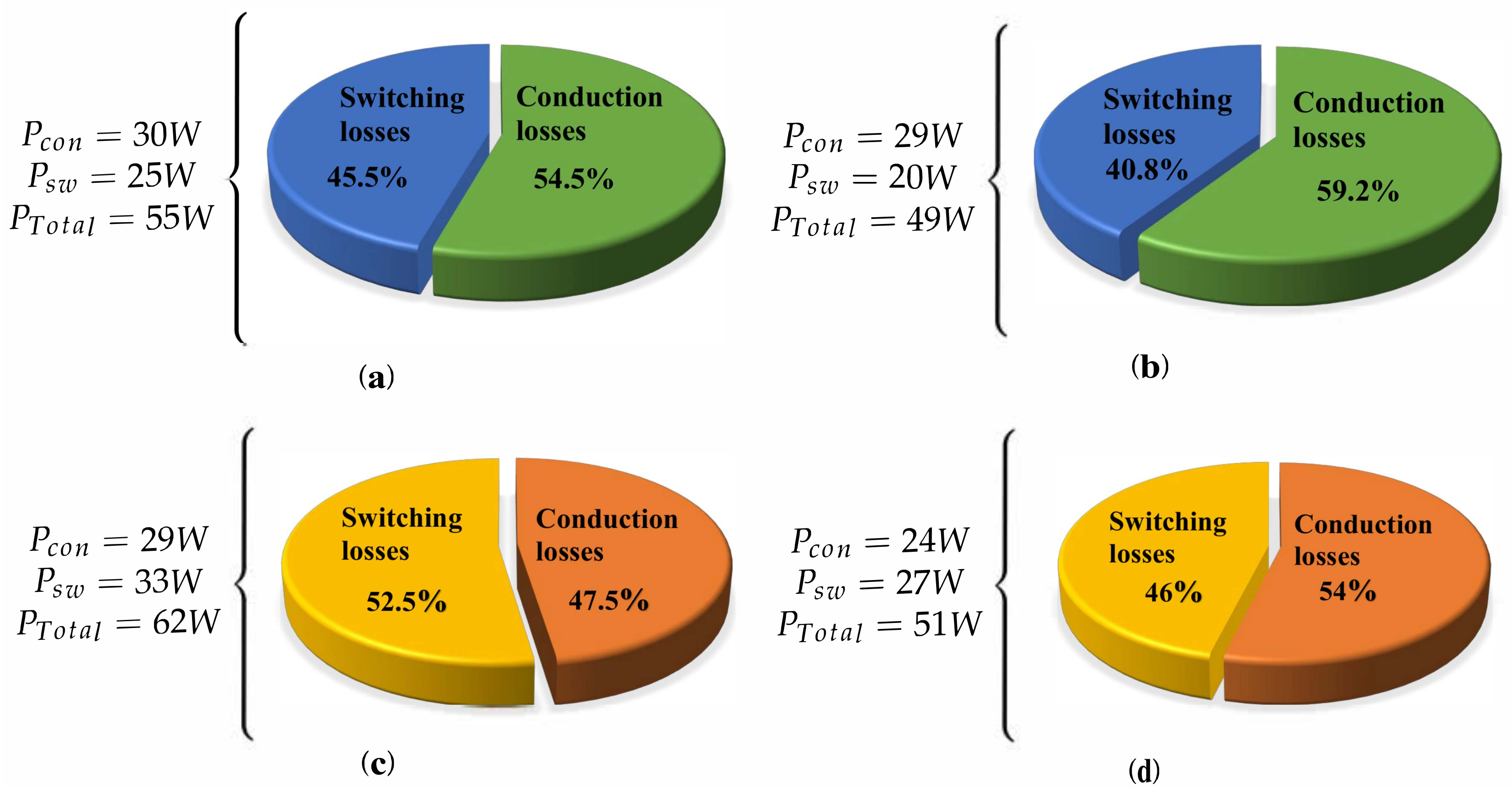
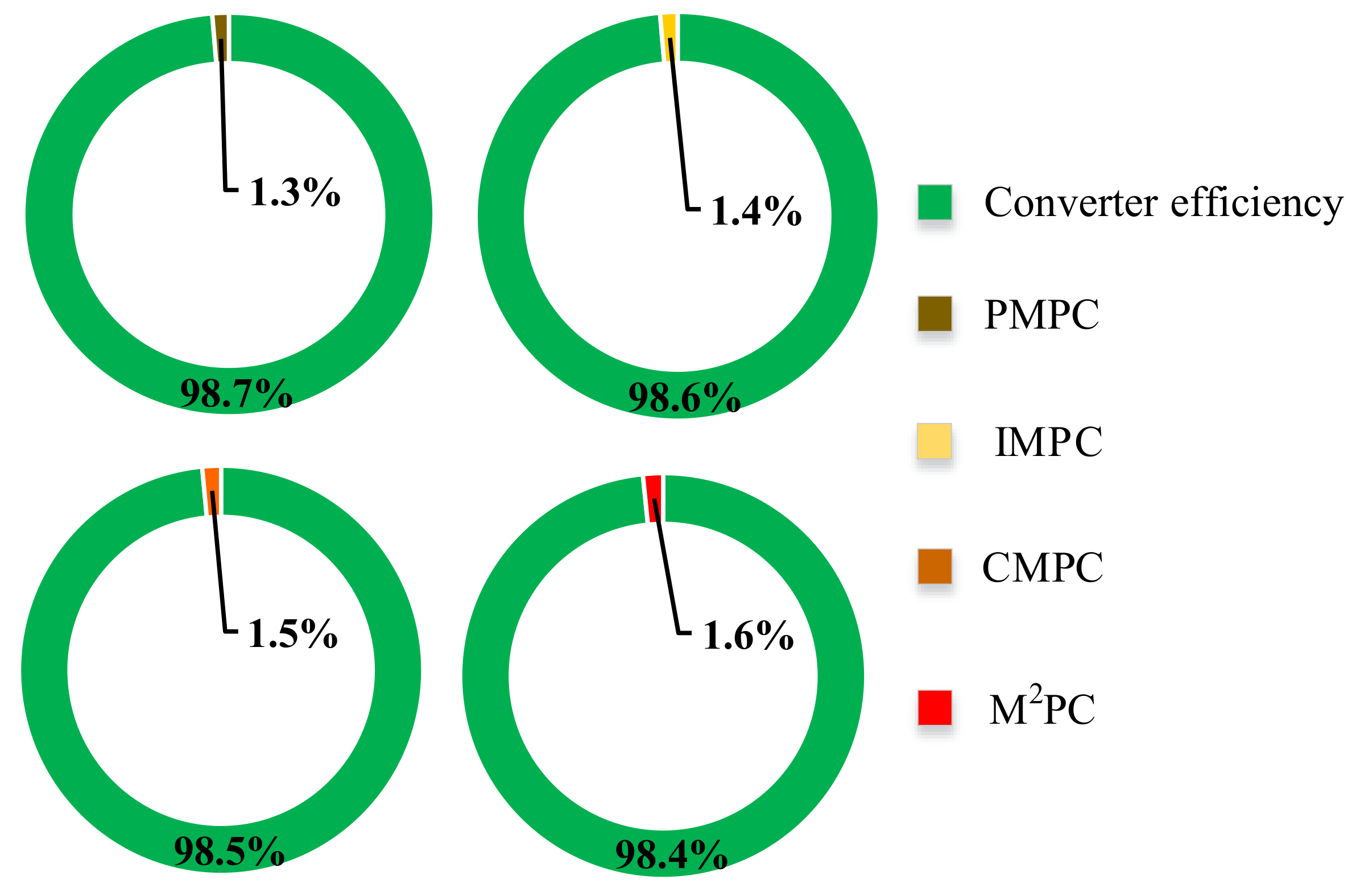
4. Power Loss Evaluation

Usually, power losses cause two consequences; one is impairing the converter efficiency, and the other is heat generation. Therefore, heat must be removed from the semiconductor devices and never be higher than a specific junction temperature (Tj) [21,22]. The allowed junction temperature in a switching device module is usually up to 125 C. In order to simulate the losses dissipation in the power electronic converter, the PLECS toolbox is used for developing the thermal model of the VSC, and to calculate conduction loss, which is given by:
P = 1 T 0 T ( v C E ( t ) i c ( t ) + r c e i c 2 ( t ) ) d t
where v C E and r c e can be determined graphically from the converter datasheets. During the commutations, losses appear due to the switching pattern. The expression of the switching loss is given by:
P o n + o f f = 2 · i r m s π · f s w · V · K
where K is the reference value as it can be derived from the converter datasheet. The power losses should be dissipated away in order to keep the semiconductor devices at a safe temperature. Thermal resistance exists due to the internal structure of the materials. Practically, two factors should be considered. Firstly, the thermal resistance must have a low value. Secondly, the cooling system must be working efficiently. The cooling system, and heat sink are simulated in this work through the PLECS toolbox and all equivalent thermal resistances are added, where a 40 C temperature is considered.

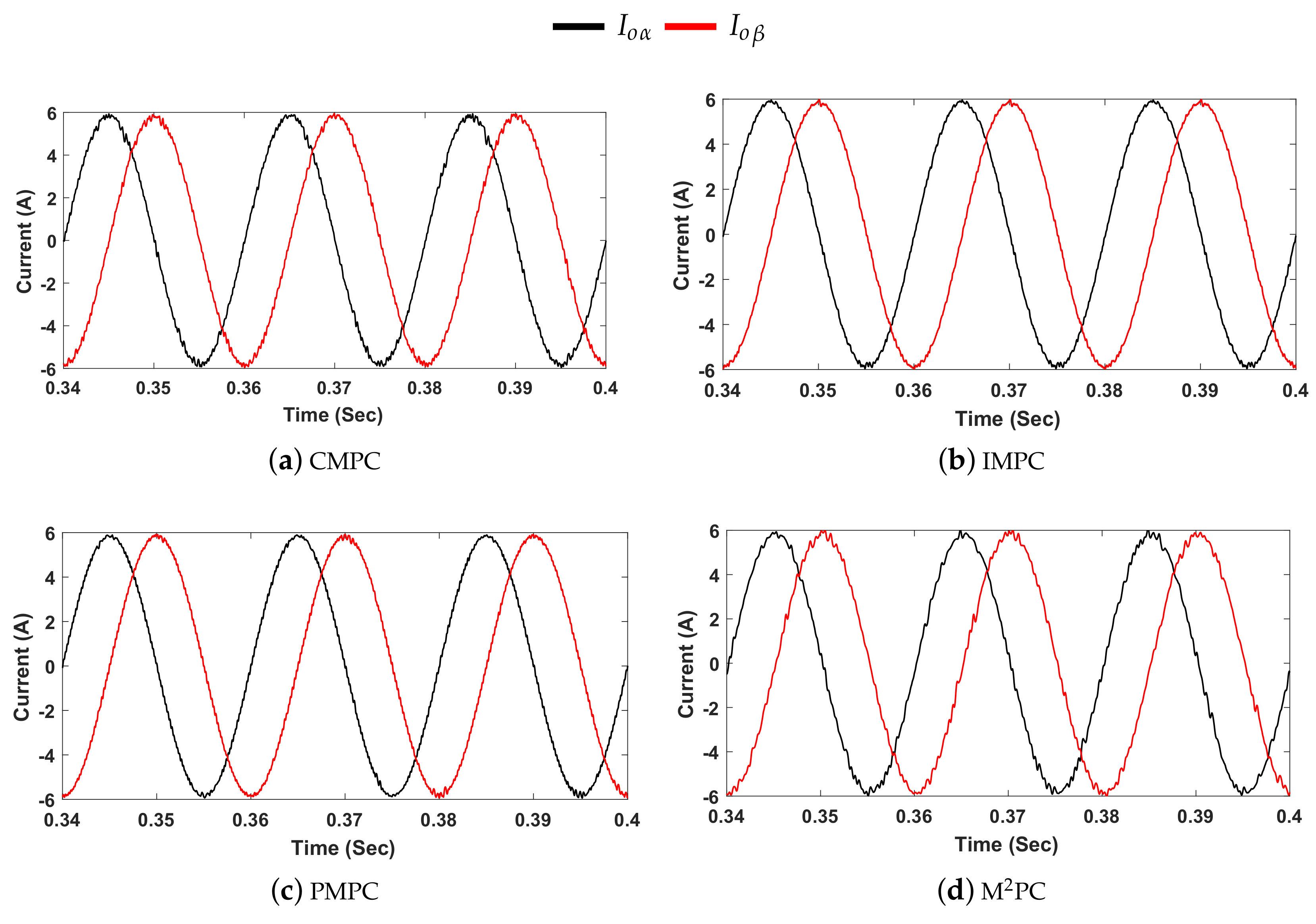
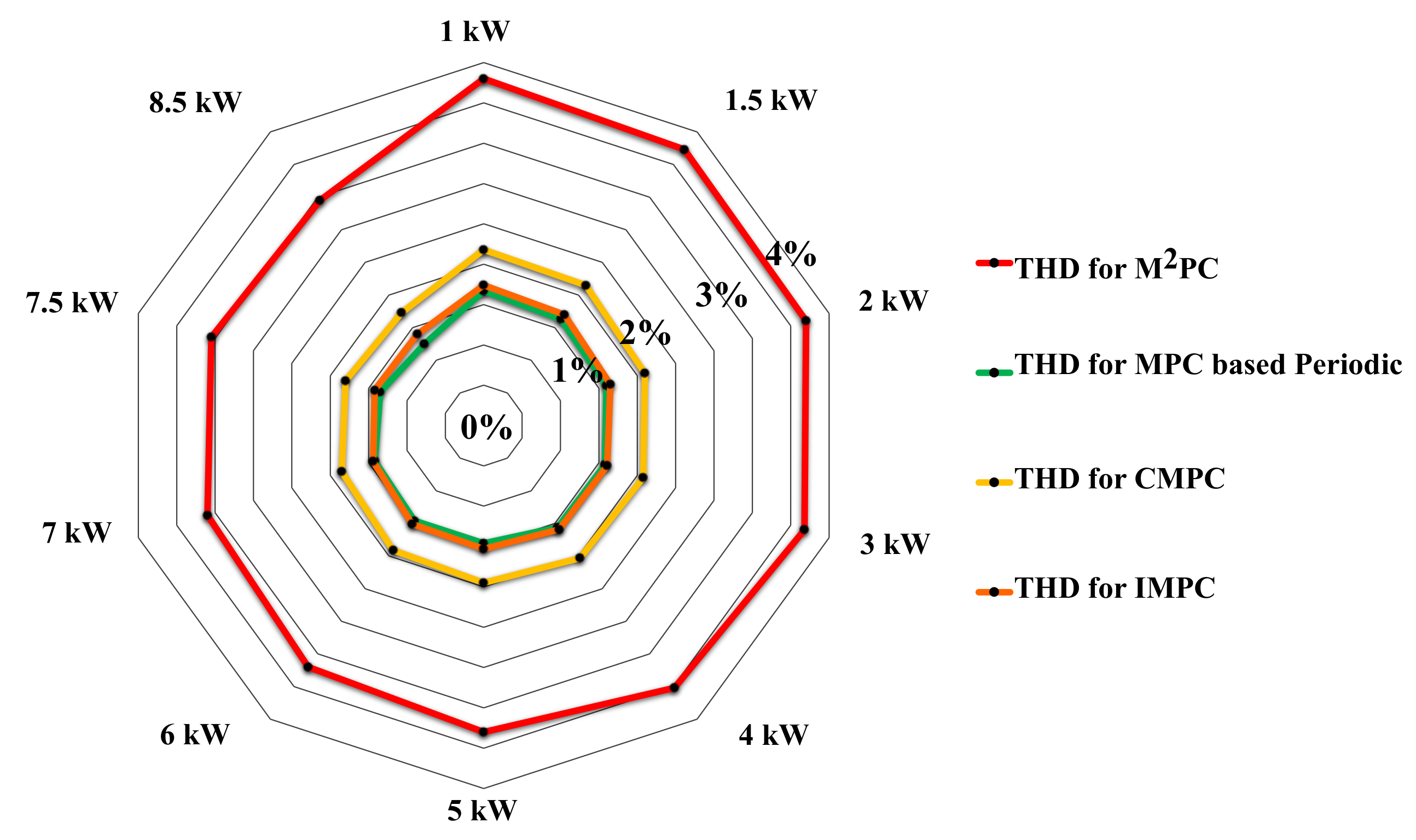
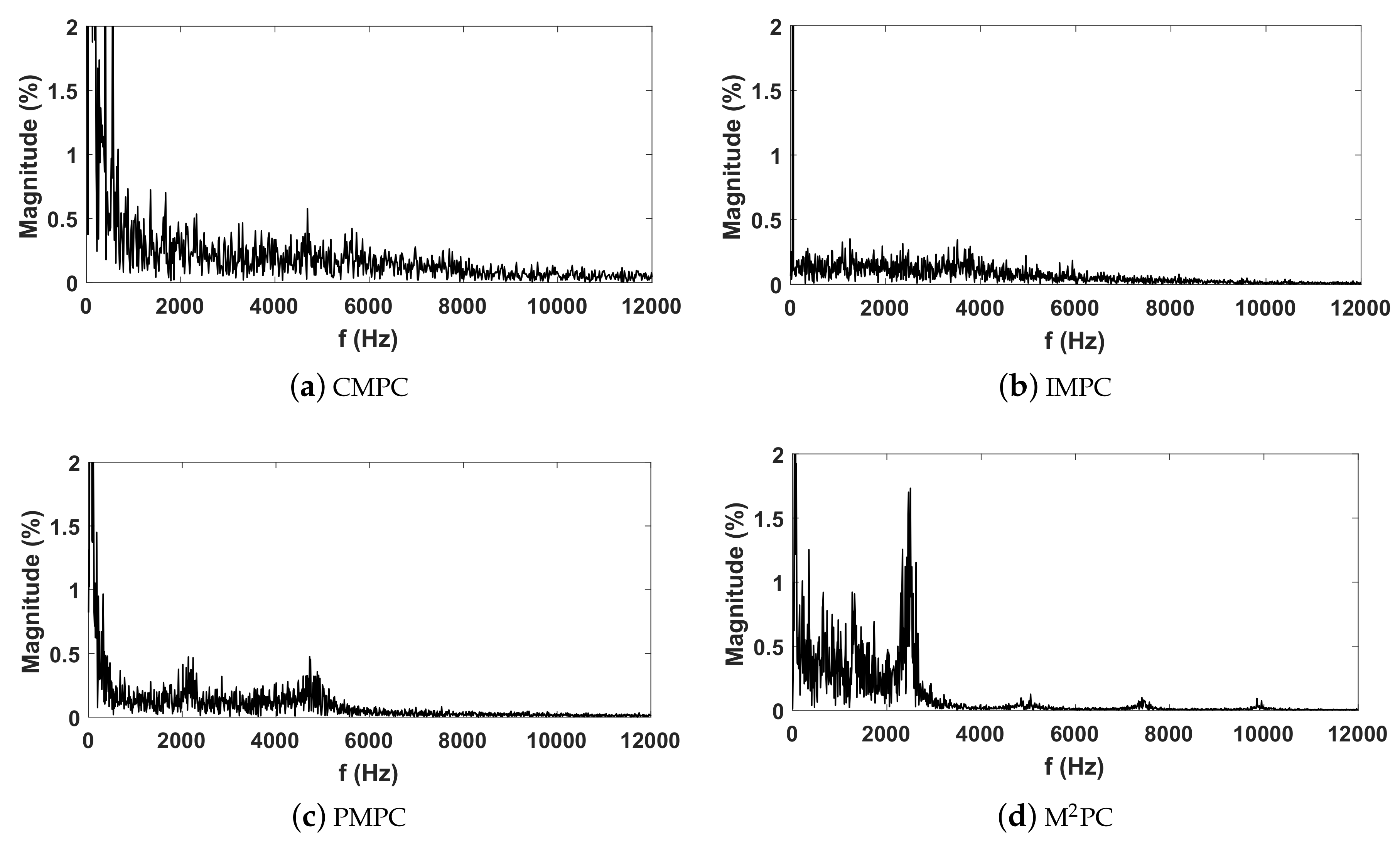
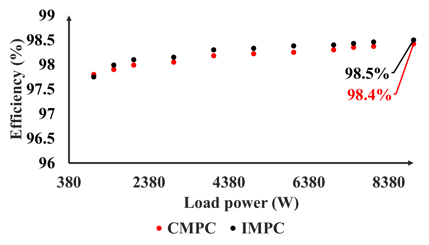
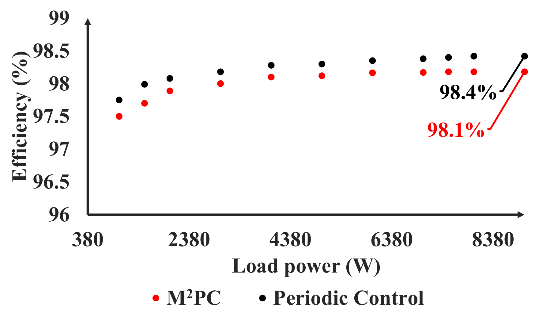
5. Results and Discussion

The control algorithms were implemented in the dSPACE controller with a DS1007 power dual-core 2 GHz processor board. The computational delay of exact T s has been compensated as in [23]. The overall parameters of the test setup and simulation model can be seen in Table 1. The conventional (CMPC), improved (IMPC), MPC scheme with a modulator (M 2 PC), and periodic (PMPC) are tested experimentally using a Danfoss three-phase 2L-VSC with an output L C filter, as seen in Figure 4 and Figure 5. An input rectifier is connected to a dc-link and fed by the main utility through a delta star transformer. The experimental validation is divided twofold: a) The investigation of the THDv for all control algorithms, where the THDv was investigated with a 600 V dc-link and line to line output voltage which is equal to 400 V rms; and b) the investigation of the losses for the 2L-VCS using the same parameters up to 8 kW.
In the losses investigation, four sets of the test have been carried out, feeding a linear load. The first and second tests consider using conventional and improved predictive algorithms. The third test is feeding a linear load, where the M 2 PC algorithm is deployed. The fourth test considers using the periodic predictive algorithm.
In line with previous studies, firstly the control algorithms should be validated with the selected circuit parameters. This kind of test implies that the control algorithms should work efficiently at the same conditions. In Figure 6a–d, it is notable that the discussed MPC control algorithms in this paper are working properly, applying the same power levels and using the same parameters. The total harmonics distortion of the applied control algorithms has been measured, and the results are included to show the importance of each control algorithm in providing a better power quality. For a fair evaluation, the switching frequency values have been considered to be approximately similar, and around 5 kHz for all algorithms. Figure 7 demonstrates that slightly superior results are achieved with the periodic control algorithm, which provides similar power quality but not using a modulator, compared to the CMPC and IMPC performance. It can be noticed that M 2 PC gives the accepted power quality and meets the grid requirement. Due to the unavoidable variations in the switching frequency using FCS-MPC, the switching states have high commutation values at higher power compared to those at lower power. Take into consideration that the calculated average is still approximately the same. In addition, FCS-MPC depends on the model of the converter associated with a physical filter to predict its future values. Based on that, changing in the measured values influences the predicted values directly and therefore, the actuations of the inverter are instantly influenced and that affects the THDv. Moreover, spectrum analysis shows the magnitude and frequency concentration for the current signals of the four MPC algorithms, as it is shown in Figure 8a–d. These results and findings are particularly important when investigating the efficiency of the power converter under different control operations.
Finally, the efficiency of the three-phase VSC is measured utilizing the discussed control strategies in this paper, and the obtained results are plotted in Figure 9 and Figure 10, in which different load points have been considered. Note that these measurements have been performed using the KinetiQ PPA5530 power analyzer.
In order to further investigate the effect of different predictive control schemes on the converter efficiency, simulation analysis is conducted. Figure 11a–d shows the distribution of the simulated switching and conduction losses at 4 kW, where the PMPC control strategy introduces much lower switching losses than the M 2 PC. It is worth mentioning that the Infineon-FF50R12RT4 module was modeled with an ambient temperature of 40 C in order to obtain the conduction and switching loss using PLECS at 8 kW rated power. Figure 12 shows the simulated efficiency for the MPC algorithms. As can be seen, the simulation results give slightly higher efficacy rather than the actual measured results in Figure 9 and Figure 10. Part of the power is dissipated due to the cable resistivity, which is not included in the simulation analysis. This is another reason that the ambient temperature is difficult to precisely estimate.
Finally, for the CPMC, IMPC, and M 2 PC, the conduction loss is approximately equal to 30 W and that due to the similar average time of duty cycles for the mentioned methods.
While for the PMPC the average time of duty cycles is less and therefore the conduction loss is approximately equal to 24 W. On the other hand, the switching loss distribution of the four MPC algorithms show how much transitions occur to deliver the same power at approximately the same switching frequency.

6. Proposal for a Standardized Switching Frequency

In this study, a new insight arises for fair efficiency comparisons of different MPC control algorithms. When the performance of the different MPC algorithms is the topic of the study, then the switching frequency variation should be standardized according to the given parameters. Hence, a proposal of how these standards should work is provided as follows:
Until now, all the FCS-MPC algorithms, which are considering an objective in the CF to obtain a fixed switching frequency, still suffer from small to medium variation range. However, most of the researchers are calculating the average switching frequency while neglecting how much the variation is. Hence, it is unclear whether the switching changes are high, medium, or low. Secondly, some of the similar works calculate the overall system efficiency where the passive filter is included, and hence, it is unclear if the filter or the control algorithms introduce the losses. Therefore, two essential guidelines are proposed here; the switching frequency variation should be ± 1000 Hz around the desired average frequency as this range does not affect the efficiency significantly. Furthermore, FCS-MPC usually has some states which hit high-frequency values rarely during the steady-state or transient operation. Therefore, the proposal suggests to neglect them as they are very few and do not influence the overall performance. Finally, it should be clearly mentioned whether the loss measurements are for the whole system, or if they are related to the converter only. Based on that, all the measurements in this work included the loss in the complete power system.

7. Conclusions

In summary, this paper conducted four FCS-MPC algorithms for the grid forming converters. The conducted control algorithms have included the conventional way of realizing the 2L-VSC by the FCS-MPC. The second control algorithm is an improvement of the conventional version of the same controller. The third control algorithm tried to fix the switching frequency by adding an objective in the CF, which solved the average variable switching frequency, and uncharacteristic switching pattern without the use of a modulator. The last control algorithm calculates the prediction of the two active vectors that compose each sector at every sampling time and evaluates the cost function separately for each prediction. The control strategies have been analyzed and compared with each other using simulation and experimental results, where a 15 kVA three-phase 2L-VSC has been utilized. The experimental results have demonstrated high efficiency using the periodic for the fixed switching frequency algorithms, while it showed the superiority of the IMPC for the variable switching frequency algorithms. Finally, new insights for similar works are introduced for the performance assessment of different model predictive schemes.

Author Contributions

Conceptualization, M.A., P.D. and F.B.; methodology, M.A.; software, M.A.; validation, M.A.; formal analysis, M.A. and P.D.; investigation, M.A.; resources, P.D. and F.B.; data curation, M.A.; writing—original draft preparation, M.A.; writing—review and editing, M.A., P.D. and F.B.; visualization, M.A.; supervision, P.D. and F.B.; project administration, P.D. and F.B.; funding acquisition, P.D. and F.B.

Funding

This research is supported by Department of Energy Technology at Aalborg University and Arab Academy for Science, Technology and Maritime Transport.

Conflicts of Interest

The authors declare no conflict of interest.

References

  1. Vazquez, S.; Leon, J.I.; Franquelo, L.G.; Rodriguez, J.; Young, H.A.; Marquez, A.; Zanchetta, P. Model Predictive Control: A Review of Its Applications in Power Electronics. IEEE Ind. Electron. Mag. 2014, 8, 16–31. [Google Scholar] [CrossRef]
  2. Vazquez, S.; Rodriguez, J.; Rivera, M.; Franquelo, L.G.; Norambuena, M. Model Predictive Control for Power Converters and Drives: Advances and Trends. IEEE Trans. Ind. Electron. 2017, 64, 935–947. [Google Scholar] [CrossRef]
  3. Rodriguez, J.; Pontt, J.; Silva, C.; Cortes, P.; Amman, U.; Rees, S. Predictive current control of a voltage source inverter. In Proceedings of the 2004 IEEE 35th Annual Power Electronics Specialists Conference, Aachen, Germany, 20–25 June 2004; Volume 3, pp. 2192–2196. [Google Scholar] [CrossRef]
  4. Rodriguez, J.; Pontt, J.; Silva, C.A.; Correa, P.; Lezana, P.; Cortes, P.; Ammann, U. Predictive Current Control of a Voltage Source Inverter. IEEE Trans. Ind. Electron. 2007, 54, 495–503. [Google Scholar] [CrossRef]
  5. Davari, P.; Yang, Y.; Zare, F.; Blaabjerg, F. Predictive Pulse-Pattern Current Modulation Scheme for Harmonic Reduction in Three-Phase Multidrive Systems. IEEE Trans. Ind. Electron. 2016, 63, 5932–5942. [Google Scholar] [CrossRef] [Green Version]
  6. Geyer, T.; Quevedo, D.E. Performance of Multistep Finite Control Set Model Predictive Control for Power Electronics. IEEE Trans. Power Electron. 2015, 30, 1633–1644. [Google Scholar] [CrossRef]
  7. Karamanakos, P.; Geyer, T.; Oikonomou, N.; Kieferndorf, F.D.; Manias, S. Direct Model Predictive Control: A Review of Strategies That Achieve Long Prediction Intervals for Power Electronics. IEEE Ind. Electron. Mag. 2014, 8, 32–43. [Google Scholar] [CrossRef]
  8. Vazquez, S.; Leon, J.I.; Franquelo, L.G.; Carrasco, J.M.; Martinez, O.; Rodriguez, J.; Cortes, P.; Kouro, S. Model Predictive Control with constant switching frequency using a Discrete Space Vector Modulation with virtual state vectors. In Proceedings of the 2009 IEEE International Conference on Industrial Technology, Gippsland, VIC, Australia, 10–13 February 2009; pp. 1–6. [Google Scholar] [CrossRef]
  9. Tomlinson, M.; Du Toit Mouton, H.; Kennel, R.; Stolze, P. A Fixed Switching Frequency Scheme for Finite-Control-Set Model Predictive Control—Concept and Algorithm. IEEE Trans. Ind. Electron. 2016, 63, 7662–7670. [Google Scholar] [CrossRef]
  10. Rivera, M. Predictive current control for a VSI with reduced common mode voltage operating at fixed switching frequency. In Proceedings of the 2015 IEEE 24th International Symposium on Industrial Electronics (ISIE), Buzios, Brazil, 3–5 June 2015; pp. 980–985. [Google Scholar] [CrossRef]
  11. Gavilan, F.; Caballero, D.; Toledo, S.; Maqueda, E.; Gregor, R.; Rodas, J.; Rivera, M.; Araujo-Vargas, I. Predictive power control strategy for a grid-connected 2L-VSI with fixed switching frequency. In Proceedings of the 2016 IEEE International Autumn Meeting on Power, Electronics and Computing (ROPEC), Ixtapa, Mexico, 9–11 November 2016; pp. 1–6. [Google Scholar] [CrossRef]
  12. Aguirre, M.; Kouro, S.; Rojas, C.A.; Rodriguez, J.; Leon, J.I. Switching Frequency Regulation for FCS-MPC Based on a Period Control Approach. IEEE Trans. Ind. Electron. 2018, 65, 5764–5773. [Google Scholar] [CrossRef]
  13. Cortes, P.; Ortiz, G.; Yuz, J.I.; Rodriguez, J.; Vazquez, S.; Franquelo, L.G. Model Predictive Control of an Inverter With OutputLCFilter for UPS Applications. IEEE Trans. Ind. Electron. 2009, 56, 1875–1883. [Google Scholar] [CrossRef]
  14. Dragicevic, T.; Alhasheem, M.; Lu, M.; Blaabjerg, F. Improved model predictive control for high voltage quality in microgrid applications. In Proceedings of the 2017 IEEE Energy Conversion Congress and Exposition (ECCE), Cincinnati, OH, USA, 1–5 October 2017; pp. 4475–4480. [Google Scholar] [CrossRef]
  15. Alhasheem, M.; Abdelhakim, A.; Dragicevic, T.; Dalessandro, L.; Blaabjerg, F. Performance assessment of the VSC using two model predictive control schemes. In Proceedings of the 2018 IEEE Applied Power Electronics Conference and Exposition (APEC), San Antonio, TX, USA, 4–8 March 2018; pp. 450–457. [Google Scholar] [CrossRef]
  16. Zhang, G.; Yang, Y.; Iannuzzo, F.; Li, K.; Blaabjerg, F.; Xu, H. Loss distribution analysis of three-level active neutral-point-clamped (3L-ANPC) converter with different PWM strategies. In Proceedings of the 2016 IEEE 2nd Annual Southern Power Electronics Conference (SPEC), Auckland, New Zealand, 5–8 December 2016; pp. 1–6. [Google Scholar] [CrossRef]
  17. Zhang, Y.; Wang, H.; Wang, Z.; Yang, Y.; Blaabjerg, F. Simplified Thermal Modeling for IGBT Modules With Periodic Power Loss Profiles in Modular Multilevel Converters. IEEE Trans. Ind. Electron. 2019, 66, 2323–2332. [Google Scholar] [CrossRef]
  18. Rodriguez, J.; Estay, P.C. Predictive Control of Power Converters and Electrical Drives; Wiley-IEEE Press: Chichester, UK, 2012. [Google Scholar]
  19. Zhang, Y.; Liu, J.; Fan, S. On the inherent relationship between finite control set model predictive control and SVM-based deadbeat control for power converters. In Proceedings of the 2017 IEEE Energy Conversion Congress and Exposition (ECCE), Cincinnati, OH, USA, 1–5 October 2017; pp. 4628–4633. [Google Scholar] [CrossRef]
  20. Young, H.; Rodríguez, J. Comparison of finite-control-set model predictive control versus a SVM-based linear controller. In Proceedings of the 2013 15th European Conference on Power Electronics and Applications (EPE), Lille, France, 2–6 September 2013; pp. 1–8. [Google Scholar] [CrossRef]
  21. Gadalla, B.; Schaltz, E.; Siwakoti, Y.; Blaabjerg, F. Thermal performance and efficiency investigation of conventional boost, Z-source and Y-source converters. In Proceedings of the 2016 IEEE 16th International Conference on Environment and Electrical Engineering (EEEIC), Florence, Italy, 7–10 June 2016; pp. 1–6. [Google Scholar] [CrossRef]
  22. Abdelhakim, A.; Davari, P.; Blaabjerg, F.; Mattavelli, P. Switching Loss Reduction in the Three-Phase Quasi-Z-Source Inverters Utilizing Modified Space Vector Modulation Strategies. IEEE Trans. Power Electron. 2018, 33, 4045–4060. [Google Scholar] [CrossRef]
  23. Cortes, P.; Rodriguez, J.; Silva, C.; Flores, A. Delay Compensation in Model Predictive Current Control of a Three-Phase Inverter. IEEE Trans. Ind. Electron. 2012, 59, 1323–1325. [Google Scholar] [CrossRef]
Figure 1. Power circuit schematic for a stand-alone voltage source converter (VSC).
Applsci 09 03513 g001
Figure 2. Voltage vectors generated by the inverter ( V i ).
Applsci 09 03513 g002
Figure 3. Various MPC schemes, where (a) depicts that no modulator was used; and (b) depicts that a modulator was used.
Applsci 09 03513 g003
Figure 4. Schematic diagram of the experimental setup.
Applsci 09 03513 g004
Figure 5. Experimental setup.
Applsci 09 03513 g005
Figure 6. Obtained I o α β currents using different MPC schemes, where the output power is 4 kW. (a) Conventional predictive scheme; (b) improved scheme from the conventional way; (c) periodic MPC scheme; and (d) MPC scheme with modulator.
Applsci 09 03513 g006
Figure 7. Total harmonics distortion of the voltage (THDv) for different MPC schemes at 5 kHz switching frequency (average).
Applsci 09 03513 g007
Figure 8. Obtained spectrum using different MPC schemes, where the average switching frequency of each MPC scheme is 5 kHz. (a) Conventional predictive scheme; (b) improved scheme; (c) periodic MPC scheme; and (d) MPC scheme with modulator
Applsci 09 03513 g008
Figure 9. Measured efficiency of the three-phase voltage source converter (VSC) using the variable switching frequency schemes, feeding a linear load.
Applsci 09 03513 g009
Figure 10. Measured efficiency of the three-phase VSC using the fixed switching frequency schemes, feeding a linear load.
Applsci 09 03513 g010
Figure 11. Different configuration MPC schemes for efficiency assessment at 4 kW rated power. (a) Distribution Please change labels k–n to a–d for conduction and switching losses of 2L-VSC using the conventional (CMPC) scheme, (b) distribution for conduction and switching losses of 2L-VSC using the improved (IMPC) scheme, (c) distribution for conduction and switching losses of 2L-VSC using the M 2 PC scheme, and (d) distribution for conduction and switching losses of 2L-VSC using the periodic (PMPC) scheme.
Applsci 09 03513 g011
Figure 12. Simulated maximum converter efficiency and the total loss amount of each MPC alogrithm at 8 kW.
Applsci 09 03513 g012
Table 1. System parameters for the simulation and experimental setup
ParameterQuantity
S15 kVA
V o a 230 V (rms)
V d c 600 V
f g 50 Hz
f s w ≈5 kHz
L f 3 mH
C f 40 μ F

