Article

Additive Friction Stir-Enabled Solid-State Additive Manufacturing for the Repair of 7075 Aluminum Alloy

Department of Materials Science and Engineering, Virginia Tech, 460 Old Turner Street, Blacksburg, VA 24061, USA
*
Author to whom correspondence should be addressed.
Appl. Sci. 2019, 9(17), 3486; https://doi.org/10.3390/app9173486
Submission received: 1 August 2019 / Revised: 17 August 2019 / Accepted: 20 August 2019 / Published: 23 August 2019

Abstract

:

Featured Application

A novel metal additive manufacturing process, additive friction stir deposition, is investigated for use in the repair of 7075 aluminum alloy parts. Repairs include the demonstration of filling through-holes and long, wide grooves. This work is of interest to the aerospace and defense industries, in which 7075 aluminum alloy is widely used in critical components for its high strength and low density. Given its good scalability, additive friction stir deposition also has a great impact on large-scale repair applications, especially in infrastructure steel repair.

Abstract

The repair of high strength, high performance 7075 aluminum alloy is essential for a broad range of aerospace and defense applications. However, it is challenging to implement it using traditional fusion welding-based approaches, owing to hot cracking and void formation during solidification. Here, the use of an emerging solid-state additive manufacturing technology, additive friction stir deposition, is explored for the repair of volume damages such as through -holes and grooves in 7075 aluminum alloy. Three repair experiments have been conducted: double through-hole filling, single through-hole filling, and long, wide-groove filling. In all experiments, additive friction stir deposition proves to be effective at filling the entire volume. Additionally, sufficient mixing between the deposited material and the side wall of the feature is always observed in the upper portions of the repair. Poor mixing and inadequate repair quality have been observed in deeper portions of the filling in some scenarios. Based on these observations, the advantages and disadvantages of using additive friction stir deposition for repairing volume damages are discussed. High quality and highly flexible repairs are expected with systematic optimization work on process control and repair strategy development in the future.

1. Introduction

High strength aluminum alloy components are widely used in aircraft, sporting equipment, and other safety-critical applications [1,2]. With corrosion, wear, or impact damages, these components need to either be replaced—which is expensive, time consuming, and inefficient—or repaired [3]. For repair, fusion welding has proved highly successful for a broad range of metals. However, using fusion welding to repair aluminum alloy (AA) 7075 components is extremely challenging owing to the material’s poor weldability, which is characterized by hot cracking and void formation during solidification and susceptibility to stress corrosion cracking after welding [4,5]. The high failure probability and unpredictable failure time from fusion welding have incited numerous studies on solid-state repair for AA 7075 [6,7,8,9].
Friction stir-enabled processes are among the most promising repair approaches for AA 7075, as the solid-state nature avoids hot cracking and high residual stresses while the intensive material flow promotes strong bonding. For example, friction stir welding and friction stir processing can heal surface cracks along the tool path, courtesy of the plastic material flow around the cracks driven by the shoulder rotation and traverse motion [10]. One drawback of these techniques is that they only reallocate the existing material. Without material addition, these friction stir-related processes are unable to heal wide cracks or repair volume defects [11,12]. Another drawback is the keyhole formed as the rotating tool retracts from the welded plate, which leaves an additional volume defect to be repaired. These drawbacks can be addressed by equipping the friction stir-related processes with filler materials. For example, in friction taper plug welding, a tapered plug is co-axially forced into a keyhole with a similar taper. This method has proved successful at sealing through-holes left by the friction stir welding of 10 mm-thick AA 2219-T87 plates [13]. Here, the taper angles of the hole and plug should be compatible, otherwise defects are likely to form at the lower part of the weld. As a result, this technique performs better for tapered holes than standard cylindrical through-holes [14,15]. Derived from friction taper plug welding, filling friction stir welding enables better repairs of volume defects, by adding a shoulder portion on the tapered plug to avoid stress concentration at the plug–hole interface. This technique has proven effective at sealing the exit holes in similar Al alloy repair (e.g., with an Al–Cu–Mg plug and an Al–Cu–Mg plate) [16], as well as in dissimilar Al alloy repair (e.g., with an AA 7075 plug and an AA 2219 plate) [17]. Other applications of a similar approach include vertical compensation friction stir welding, friction bit joining, and stationary shoulder friction stir welding [17,18,19,20,21,22]. Recently, refill friction stir spot welding has been demonstrated to be effective at filling keyholes in AA 6061-T6 [11] as well as AA 7075-T651 [23], with the welded samples showing ultimate tensile strength as high as 74% of the base material.
While the ‘friction stir-filler’ solutions have been effective at filling volume defects like keyholes, they are stationary and require an additional step to place the filler plug of desired geometry into the hole before repair. Moreover, without the capacity to continuously add material, these processes are limited to certain defect geometries defined by the size and shape of the hole. In order to repair various types of volume damages in AA 7075—including keyholes, long grooves, large-scale corrosion or wear damages—it is vital to develop a versatile solid-state technique that can continuously supply filler material, while also allowing for digital control of the material addition and repair paths. Such a technique remained elusive until the recent emergence of a solid-state metal additive manufacturing technique—additive friction stir deposition [24,25,26]. Additive friction stir deposition integrates the friction stir principle with a robust material feeding mechanism to enable site-specific deposition. It leverages the benefits of friction stir—e.g., in the prevention of hot cracking, high residual stresses, and void formation—while providing the additional capability of adding material for a more robust repair of volume damages. The current tool size in additive friction stir deposition enables a high build rate, ~103 cm3/h for Al alloys [24], which is uniquely suitable for the large-scale repair of AA 7075.
Despite the great potential for repair of AA 7075, the research in additive friction stir deposition is still at an initial stage and there is a lack of feasibility studies on this topic. The aim of the present work is to bridge this gap. As a first attempt to use additive friction stir deposition for repairing volume damages in AA 7075, this work investigates the filling of both cylindrical through-holes and long, wide square grooves. Such repair geometries are critically important for a wide variety of aerospace and defense applications [3,17,23,27]. For each of these defects, we will elaborate the repair strategy, examine the repair quality, discuss the benefits and limitations of additive friction stir deposition-enabled repair, and provide comparisons to other repair approaches.

2. Materials and Methods

All additive friction stir depositions were performed using a MELD R2 system (MELD Manufacturing Corporation, Christiansburg, VA, USA) with a rotation rate of 400 RPM. Three types of experiments were performed. Experiment 1 involved double hole filling, in which two cylindrical through-holes with the diameters of 6.35 mm (i.e., 1/4”) and 3.125 mm (i.e., 1/8”) were drilled in series into an AA 7075 plate. In this work, double hole filling using additive friction stir deposition was implemented by (i) traveling of the tool (i.e., the print head); (ii) dwelling (i.e., zero traverse speed); and (iii) traveling again. Experiment 2 involved single hole filling, in which one cylindrical through-hole with the diameter of 6.35 mm (i.e., 1/4”) was drilled into the plate. In this work, single hole filling using additive friction stir deposition was implemented by (i) traveling; (ii) dwelling; and (iii) the lift of the tool. In Experiment 1 and Experiment 2, the traverse speed during tool traveling was 0.32 mm/s and the linear feed rate was 0.1 mm/s. Experiment 3 involved the filling of long, wide grooves, which were 12.7 mm (i.e., 1/2”) wide, 3.175 mm (i.e., 1/8”) deep, and 304.8 mm (i.e., 12”) long. In this work, such groove filling was implemented by the slow traveling of the tool without dwelling, wherein the traverse speed was 0.42 mm/s and the linear feed rate was 0.06 mm/s. The details of the three types of experiments are summarized in Table 1. Figure 1 shows an image of the additive friction stir deposition facility along with the hole filling and groove filling illustrations.
In all experiments, 6.35 mm thick commercial AA 7075-T651 plates were used as the substrate, with the cylindrical holes and long wide grooves machined as specified in Table 1. The measured composition of the plates is summarized in Table 2. The feed material for additive friction stir deposition was also cut from the commercial Al 7075-T651 plates, with a cross-section of 9.535 × 9.535 mm2. After the repair experiments, cross-sections of the filled holes and grooves were cut and polished using standard metallographic techniques. For electron microscopy, the samples were first etched with a caustic mixture, consisting of 1 g of NaOH and 100 mL of water, in order to reveal the grain boundaries. For optical microscopy, samples were electro-etched using 50 mL of Barker’s reagent etching solution—comprised of 1.9 mL of 48 wt.% HBF4 solution and 48.7 mL of H2O—with an etching voltage of 30 V for 1 min. Polarized optical microscopy (Zeiss, Oberkochen, Germany) and scanning electron microscopy (SEM; Helios Nanolab 600 DualBeam, Waltham, MA, USA) were used to characterize the microstructures after repair. For optical microscopy, multiple images were taken and stitched together using ImageJ, an open-source image processing software, to allow for a holistic view of the entire cross-section. Microhardness testing was performed using a Leco LM100AT (St. Joseph, MI, USA) microhardness tester at 300 N load and with 10 s dwell time. Hardness for the single hole filled sample was measured using 20 points along the width of the repair cross-section with a spacing of 0.5 mm and 14 points along the height of the repair with a spacing of 0.4 mm. The groove sample was tested at 20 points along the width of the repair with a spacing of 1.0 mm and 9 points along the height of the repair with a spacing of 0.6 mm.

3. Results

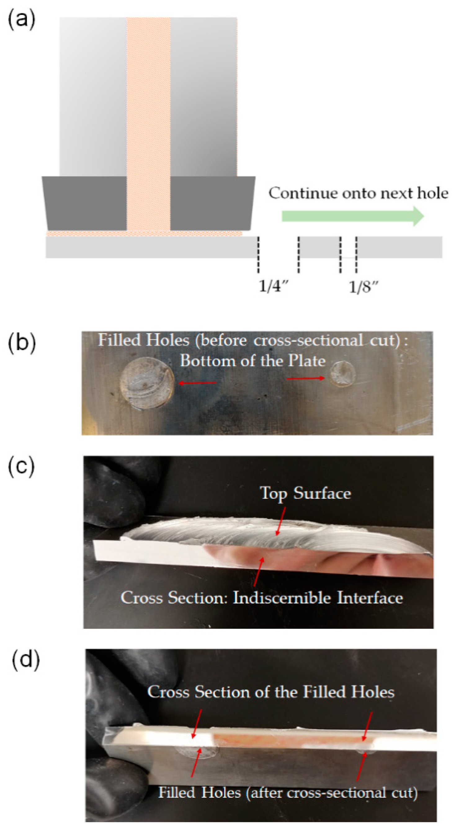
3.1. Double Through-Hole Filling

For double hole filling, the deposition begins close to the edge of the large hole (i.e., the 1/4” hole), and then the print head travels toward the hole while simultaneously depositing a continuous track of AA 7075 on the top surface of the AA 7075 plate. The in-plane motion of the print head stops when it aligns with the center of the hole. This is followed by a dwelling phase, in which the print head continues to rotate and deposit new material without in-plane motion, in order to allow for enough AA 7075 to fill the hole. For this experiment, the tool rotation rate is held constant at a rate of 400 RPM, the material feed rate is 0.1 mm/s, and the in-plane velocity is 0.32 mm/s when traveling. Figure 2 shows several snapshots of the traveling and dwelling phases of this repair approach. The print head is held stationary until the edge of the deposition track begins to push out beyond the edges of the tool print head, suggesting that the hole is fully filled and there is an excess of material. Once the excess of material is observed, in-plane motion towards the second hole (i.e., the 1/8” hole) begins. The in-plane motion stops again when the print head aligns with the center of the second hole, which is also followed by a dwelling step for material filling. The entire repair process is illustrated in Figure 3a. Figure 3b–d show the AA 7075 plate after repair using additive friction stir deposition. Figure 3b shows the bottom of the plate after repair. It can be seen that the deposited material is able to reach the bottom of the cylindrical holes. Figure 3c,d show that the two holes are completely filled by the deposited AA 7075 from the top to the bottom, without apparent defects. The side wall of the hole appears to be fully mixed with the deposited material, manifesting indiscernible interfaces in the cross-sectional images.
We have also examined the microstructure of the repaired holes. Figure 4a shows a large-area SEM micrograph of the lower half of the 1/4” hole after repair, which again confirms that the deposited material fills the entire cylindrical through-hole. In addition, there is no defect observed at the interface (marked as ‘hole wall edges’) between the deposited material and the surface of the hole, suggesting that there is sufficient mixing and adhesion between the two. A zoomed-in image of the interfacial region (after electro-etching) is shown in Figure 4b, featuring a curved, rather than a straight and sharp interface. The curved interface is a sign of co-plastic deformation of the deposited material and the side wall material, which involves intensive material flow and mixing between the two. Such curved interfaces and the associated structural interlocking are expected to lead to substantially stronger interfacial bonding than alternative coating or repair processes. More importantly, Figure 4b shows distinct microstructures between the filled AA 7075 and AA 7075 plate. The former generally exhibits an equiaxed and refined microstructure, with the average grain size of 3.4 ± 0.7 µm, whereas the latter exhibits elongated grains that are typical of the rolling microstructure of Al alloys. It is noted that the starting microstructure of the feed material is the same as the plate—i.e., with elongated grains. This result thus shows that additive friction stir deposition-enabled repair can significantly modify the microstructure of the feed material, resulting in equiaxed, fine grains through dynamic recrystallization. For AA 7075, the grain refinement is expected to proceed via dynamic recovery, which leads to sub-grain formation, followed by strain-induced grain rotation, resulting in high angle grain boundaries [28,29]. This process is generally referred to as continuous dynamic recrystallization, which has been observed in the additive friction stir deposition of other Al alloys [30,31].

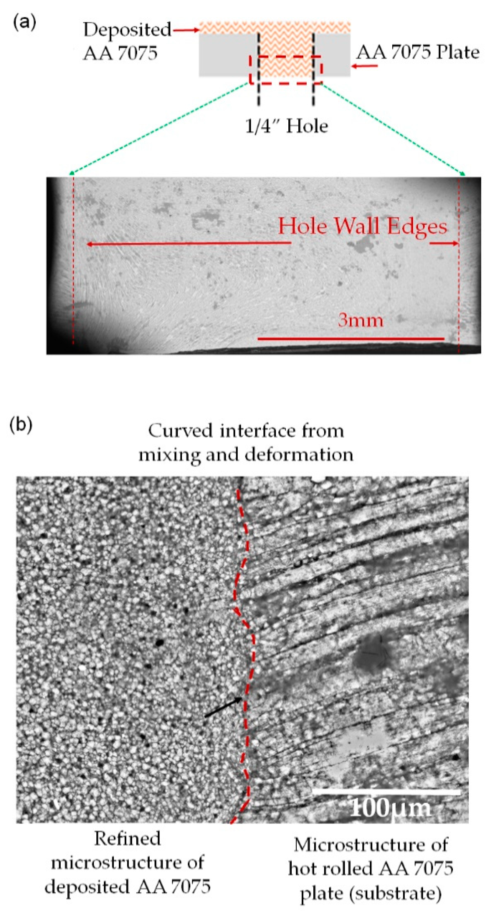
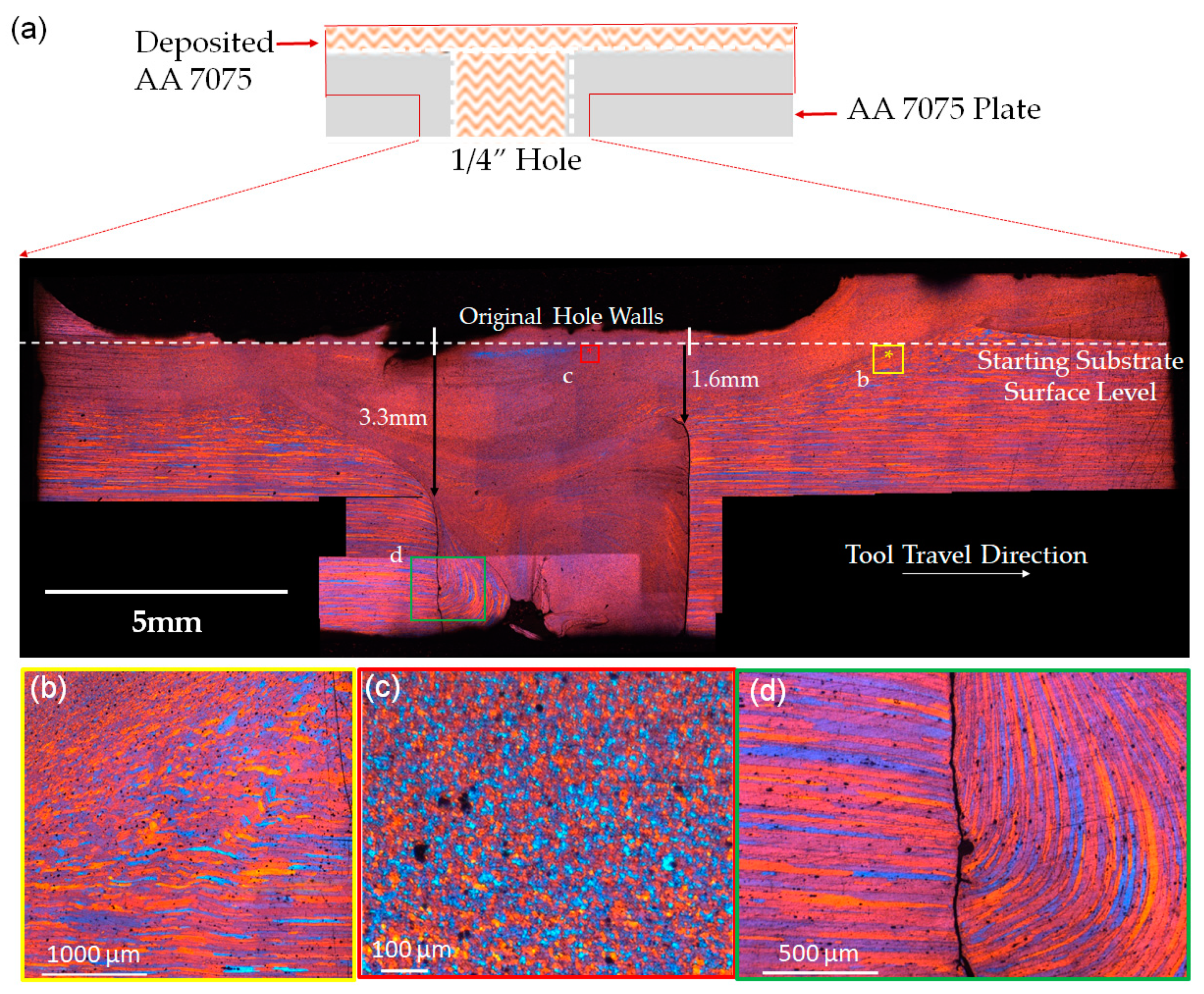
3.2. Single Through-Hole Filling

For single hole filling, the deposition starts close to the edge of the hole. This is followed by the print head traveling along the centerline of the hole until it reaches the center of the hole. After that, the print head stays over the hole for a pre-determined amount of time: the dwell time of 3 min, which controls the amount of filling material. Once the dwell phase finishes, no further traveling is applied. Instead, the print head is lifted while still rotating, so that the feed rod breaks off from the deposited material. Similarly to Experiment 1, the tool rotation rate is held constant at a rate of 400 RPM, the material feed rate is 0.1 mm/s, and the in-plane velocity is 0.32 mm/s. Figure 5 shows the top and cross-sectional views of the as-repaired sample with the 3 min dwell time. As can be seen from the images, additive friction stir deposition does not result in keyholes that are observed in friction stir welding; the breakage of the feed rod merely results in a rough surface at the end of deposition. In practical repair applications, the tool head could be retracted more slowly to allow this area to be flatter.
A representative microstructure image of the repaired hole in cross-sectional view is shown in Figure 6a, which is comprised of multiple optical micrographs stitched together. Magnified views of various features in 6a are illustrated in Figure 6b–d. As a whole, Figure 6a depicts the extent and shape of the mixing that occurs between the deposited material and the plate. The majority of the cylindrical through-hole has been successfully filled by the deposited AA 7075. Additionally, sufficient mixing between the deposited material and side wall of the hole is observed in the upper portions of the repair. These good mixing zones are generally comprised of a gradual transition from the elongated grains of the AA 7075 plate to the fine, equiaxed grains of the deposited AA 7075, meaning that no distinct interface is present. An example of such a transition zone is illustrated in Figure 6b, which also shows varying degrees of grain deformation and grain refinement within this zone. The typical microstructural features of the refined equiaxed grains (grain size < 10 µm) of the deposited AA 7075 are shown in Figure 6c. It should be noted that the black spots that appear in Figure 6b,c are most likely due to pitting, which is a result of over-etching during sample preparation.
The repair quality of this sample is visibly worse when compared to the double hole fill sample in Section 3.1. In the lower portions of the repaired hole shown at the bottom of Figure 6a, a void of ~1 mm x 1 mm in cross-section is observed; moreover, there are distinct, sharp interfaces separating the side wall of the hole and the deposited material (Figure 6d), suggesting inadequate mixing and weak interfacial adhesion. The starting points of these distinct interfaces are highlighted by the two black arrows in Figure 6a, showing that only the top ~1.6–3.3 mm portion of the hole has been well mixed. The depth of the sufficient mixing zone is greater on the left side where the print head first travels over the hole. Across the sharp interface, the inside features fine grains from the deposition, whereas the outside features the elongated grains that are characteristic of the rolled plate.
Intriguingly, Figure 6a depicts a large section of elongated grains present at the bottom of the hole underneath the deposited material. Note that these elongated grains are only on the side of the hole from which the print head passes over, i.e., the left side of the image. Therefore, this unique region possibly originates from the plate material near the hole. A mechanism is proposed to explain this finding in Section 4.1. Figure 6d shows a magnified view of this unique region—elongated grains are present on both sides of the interface, but with different elongation orientations.

3.3. Long, Wide Groove Filling

To fill the long, wide groove, the print head is first placed above the groove and begins to rotate at 400 RPM without traveling. Feed material is simultaneously forced down into the groove. The dynamic contact between the feed material and the bottom of the groove leads to frictional heating so that the feed material is plasticized. Once the feed material begins spreading out under the print head to reach the side walls of the groove, slow traveling at a rate of 0.42 mm/s starts along the longitudinal direction of the groove with a material feed rate of 0.06 mm/s. Upon the completion of the first layer, the print head reverses direction to deposit another layer on top of the already deposited track. Finally, to ensure good filling, a third traverse is conducted over the two previous deposition layers, with the intention of pushing more material into the groove. Each layer after the first is approximately 0.76 mm in height. Figure 7a,b show the top view and cross-sectional view of the as-repaired groove, respectively.
A stitched optical image for the entire cross-section of the repaired groove is shown in Figure 7c, which confirms complete volumetric filling, notwithstanding the increased volume to fill and the increased distance from the print head to the side wall of the 1/2” wide groove. Unlike in single hole filling, no voids are observed after the groove filling. Moreover, the upper portions of the repair show sufficient mixing between the deposited material and the side wall of the groove, which is indicated by the lack of a distinct interface. Nevertheless, the depth of sufficient mixing (below the starting substrate surface level) is generally in the range of 1.31–1.68 mm, as highlighted by the two black arrows. This range is only about half of the groove depth. Addressing the inadequate mixing in the lower half of the repair is a critical necessity.
Compared to the hole filling experiments where the feed rod diameter is too large to be placed into the hole, the groove filling experiment involves direct contact of the feed rod to the bottom of the wide groove. Even with such direct contact, the repair quality of the lower portions of the groove is still not satisfactory. This implies that the initial pass of the print head is insufficient at mixing the two materials and that subsequent passes are not able to penetrate deep enough to facilitate further mixing. Examining the interior region of the repaired groove, sharp internal boundary features are observed close to the bottom of the groove, which are implied by the stark black lines. These boundaries originate from the complex material flow occurring during repair as indicated by the flow lines, which can be controlled by the processing parameters and travel paths of additive friction stir deposition. A degree of material separation occurs in the boundary regions, making it highly susceptible to crack initiation and growth upon mechanical loading.
Notably, the complete groove filling here is implemented by a single-track of deposition, even though the width of the groove is 33% larger than the width of the feed rod. Such a wide groove, on the other hand, imposes challenges for forming a strong interface between the deposited AA 7075 and groove side walls, because it requires significant material flow and deformation in the interfacial regions. The issues of poor mixing and internal boundaries observed at the bottom of the groove may possibly be addressed by employing multiple tracks of deposition inside the wide groove, with the neighboring tracks overlapped.

3.4. Microhardness Testing

Figure 8 shows representative hardness maps measured from the cross-sections of the repaired hole (Experiment 2) and the groove (Experiment 3), respectively. The dashed lines represent the original dimensions of the defects to be repaired. The measured peak hardness is 172 HV in the repaired hole, and 168 HV in the repaired groove. In the deposited material, the hardness shows higher values inside the repaired volume than at the interface of mixing, a trend observed in both hole and groove repair. The average hardness of the feed rods is measured to be 164 HV. Although the deposited material is generally softened when compared to the original feedstock, most of the repaired volume exhibits a hardness value above 140 HV, which is 85% of the feed material value. There are even localized areas in the repaired volume showing comparable hardness to the stock AA7075-TT651.
Through additive friction stir deposition in this work, the grain size of AA 7075 is reduced from several hundreds of microns in the feed material to a few microns in the deposited material, which alone should lead to a slight increase in the strength and hardness. However, additive friction stir deposition of AA 7075 has been carried out in the range of 80–90% of the melting temperature of aluminum, which is close to or above the solutionizing temperature of AA 7075 [32,33]. Although the typical exposure to the peak temperature lasts only for a few seconds in additive friction stir deposition, the extended dwell period in repair could cause a significant portion of precipitates to dissolve into the lattice. Such a substantial weakening of precipitation hardening ultimately results in the decrease of the microhardness in the as-deposited material. Compared to the repaired volume, the edges of the hole and groove—which consist of elongated grains—exhibit even lower values of hardness. This is because the AA 7075 at these locations undergoes much less deformation than the deposited material, resulting in no dynamic recrystallization. Instead, the material is mostly in the thermomechanically-affected zone or heat-affected zone. The resultant grain growth and precipitate dissolution can thus lead to a lower value of hardness than the deposited material.

4. Discussion

4.1. Interactions between the Deposited Material and Large-Volume Damage during Additive Friction Stir Deposition

In friction stir welding literature, poor bonding is typically characterized by many visible defects including voids, kissing bonds, delamination, and underfilling. This often results in lowered mechanical performance (ductility, strength, wear, etc.), as these defects act as crack initiation sites under stress [34]. A good repair is characterized not only by a lack of these defects, but in the case of friction stir-based processes, by a gradual transition from the base material to the stirred material. In this case, the material flow during processing crosses the original geometry of the hole and eliminates any visible interface between the repair and base materials. This gradual transition typically leads to strong adhesion between the base material and the repair volume and minimizes the likelihood of failure at the repair.
Examining all repair experiments, we can conclude that sufficient material flow that enables to eliminate any sharp interface between the deposited material and the side wall of the hole or groove always occurs at the upper portions of the repaired structure. In the lower portions of the repair—particularly in Experiment 2 and Experiment 3—cracks and kissing bonds can be observed, which suggest a lack of mixing between the side wall and the deposited material. These notches and rough surfaces at the bottom of the repair volume could act as initiation sites for cracks and ultimately lead to the failure of the repair, but an optimization of the processing conditions could lead to significantly improved quality of repair. The depth of mixing in additive friction stir deposition depends on the dimensions and shape of the damage (i.e., the fill geometry) and the repair procedures using additive friction stir deposition. In this work, the double hole filling experiment is the only repair to show no visible interfaces or defects. A striking difference between the double hole filling experiment and the other experiments is that the former exhibits multiple instances of tool traversal perpendicular to the wall edge, which is enabled by the initial traveling as well as the traveling after dwelling. This can be a key factor in improving the depth of mixing and the repair quality during additive friction stir deposition. This idea is further supported by the observation that in the single hole filling experiment, the repair side from which the print head approaches and crosses over demonstrates deeper and more complete mixing.
The proposed mechanism for interactions between the deposited material and hole edges is illustrated in Figure 9. As shown in Figure 9a, in additive friction stir deposition, the force imposed onto the deposited material transmits stresses onto the substrate, leading to substantial material flow of its surface layers together with the deposited material. Along the edges of the stir zone, the substrate material experiences lower degrees of deformation, effectively forming the thermo-mechanically affected zone as described in other friction stir-related processes [35]. As the deposited material is pushed by the tool (i.e., the print head) to traverse toward the hole, the top edge of the hole interacts with the deformation front of the stir zone, deforming and eventually moving with the advancing material. This deformation process may involve bending deformation of the hole edges or even shear-induced fracture. As illustrated in Figure 9b, the fractured hole edge pieces may end up at the bottom edge of the hole, which is consistent with our observation of single hole filling in Figure 6d.

4.2. Comparisons to Other Friction Stir-Based Repair Approaches

Comparing the preliminary results of additive friction stir deposition in this work to other friction stir-based repair approaches—such as friction taper plug welding, filling friction stir welding, and refill friction stir spot welding (RFSSW) [13,16,23]—the latter are currently more mature, producing remarkable repair quality. Most notably, RFSSW has been demonstrated to successfully fill 7xxx aluminum through-holes of similar sizes to that in the present study [23]. While the final microstructure in the repaired volume is similar in additive friction stir deposition and RFSSW, RFSSW demonstrates excellent mixing throughout the depth of the hole, without any gaps observed at the interface between the plug and the hole wall. Comparable repair quality and interfacial mixing are achieved in Experiment 1, but the single hole filling in Experiment 2 and the groove filling in Experiment 3 show inadequate mixing in the lower portions of the repair.
Despite the imperfect repair quality demonstrated in Experiment 2 and Experiment 3 in the present work, the potential of large-volume repair using additive friction stir deposition should never be underestimated. First, additive friction stir deposition is able to robustly add material, so it is flexible with the repair geometry, whether it is a keyhole, long trench, or wide groove. The plug-based friction stir approaches, while enabling sufficient mixing and good repair quality, are limited by their repair geometry, not to mention the additional need of fabricating plugs of specific sizes and shapes. It would be quite challenging, if possible at all, to use these approaches to repair the long, wide groove shown in Experiment 3. Second, the results presented in this work represent the first attempts at using additive friction stir deposition to repair AA 7075. No optimization work has been performed regarding the deposition parameters (e.g., traveling speed and rotation rate), the dwell time, or the repair strategy (e.g., single vs. multiple tracks of deposition). Furthermore, the tool geometry can be tailored to the specific shapes and sizes of damages, and tool design will likely play an important role in large-volume repair in any future research of additive friction stir deposition. With systematic optimization work on these aspects, additive friction stir deposition should enable much improved repair quality than is demonstrated in the present work.
We note that the fine grain microstructure in the repaired volume is a result of additive friction stir deposition that may affect other properties of the component, such as corrosion resistance. Both positive and negative effects of small grain sizes by friction stir processing have been reported in literature on the corrosion performance [36,37,38]. This aspect remains to be explored for additive friction stir deposition-based repair.

5. Conclusions

To summarize, we have explored the use of additive friction stir deposition, an emerging solid-state additive manufacturing technology, for the repair of volume damages in AA 7075. The most salient conclusions from this work include:
  • Additive friction stir deposition proves to be effective at filling the entire volume of through-holes and wide grooves in AA 7075. This is especially noteworthy in the latter case, in which the width of the groove is 33% larger than the width of the feed rod.
  • Additive friction stir deposition always enables sufficient mixing between the deposited material and the side wall of the hole or groove in the upper portions of the repair. This is indicated by a gradual transition from the elongated grains of the AA 7075 plate to the fine, equiaxed grains of the deposited AA 7075, showing no distinct interface.
  • The repair quality of the lower portions is generally worse than the upper portions, sometimes showing straight, sharp interfaces separating the elongated grains and the fine, equiaxed grains. In through-hole filling, the depth for sufficient mixing is controlled by the interactions between the deposited material and the hole edges, which may involve the bending or even fracture of the hole edge pieces.
  • The thermomechanical history in additive friction stir deposition generally leads to a slight decrease (<15%) in the hardness of the repaired volume as compared to the original feed material, although the peak hardness in the repaired volume can be comparable to the feed material.
Overall, this work presents an initial investigation on the solid-state additive repair of AA 7075 using additive friction stir deposition, which shows promising results despite imperfect repair quality. With systematic optimization work on process control and repair strategies developing in the future, high-quality and highly flexible repairs are expected to be achieved using additive friction stir deposition.

Author Contributions

Within this study, conceptualization of the project was carried out by R.J.G., D.G., and H.Z.Y. Experimental methodology was planned by R.J.G. and D.G. Formal analysis on data was performed by R.J.G. and D.T.P. Investigation of study was carried out by R.J.G., D.T.P., and D.G. Resources were provided and created by R.J.G., D.T.P., and H.Z.Y. Data curation and data management was the responsibility of R.J.G. and D.T.P. For the manuscript, the original draft was prepared by R.J.G., D.T.P., D.G., and H.Z.Y. Review and editing was performed by R.J.G., D.T.P., D.G., and H.Z.Y. Data visualization was performed by, R.J.G., D.T.P., D.G., and H.Z.Y. Supervision of work and project administration was the responsibility of H.Z.Y. Internal funding was acquired by H.Z.Y.

Funding

This research received no external funding. The APC was funded by the Department of materials science and engineering and College of Engineering at Virginia Tech.

Acknowledgments

Part of this work is an outcome of a senior design project supported by the Department of Materials Science and Engineering at Virginia Tech, which the authors would like to acknowledge. The authors would also like to acknowledge Emily Bautista and David Kang for their help in experiment.

Conflicts of Interest

The authors declare no conflict of interest.

References

  1. Kumar, P.V.; Reddy, G.M.; Rao, K.S. Microstructure, mechanical and corrosion behavior of high strength AA7075 aluminium alloy friction stir welds—Effect of post weld heat treatment. Def. Technol. 2015, 11, 362–369. [Google Scholar] [CrossRef]
  2. Veeravalli, R.R.; Nallu, R.; Mohiuddin, S.M.M. Mechanical and tribological properties of AA7075–TiC metal matrix composites under heat treated (T6) and cast conditions. J. Mater. Res. Technol. 2016, 5, 377–383. [Google Scholar] [CrossRef]
  3. Liu, Y.; Mol, J.M.C.; Janssen, G.C.A.M. Combined Corrosion and Wear of Aluminium Alloy 7075-T6. J. Bio Tribo Corros. 2016, 2, 9. [Google Scholar] [CrossRef]
  4. Lippold, J.C. Welding Metallurgy and Weldability; John Wiley & Sons Inc.: Hoboken, NJ, USA, 2015; p. 1. [Google Scholar]
  5. Çam, G.; Mistikoglu, S. Recent Developments in Friction Stir Welding of Al-alloys. J. Mater. Eng. Perform. 2014, 23, 1936–1953. [Google Scholar] [CrossRef]
  6. Threadgill, P.L.; Leonard, A.J.; Shercliff, H.R.; Withers, P.J. Friction stir welding of aluminium alloys. Int. Mater. Rev. 2009, 54, 49–93. [Google Scholar] [CrossRef]
  7. Grushko, O.; Ovsyannikov, B.; Ovchinnikov, V. Aluminum-Lithium Alloys: Process. Metallurgy, Physical Metallurgy, and Welding, Advances in Metallic Alloys; Taylor & Francis, CRC Press: Boca Raton, FL, USA, 2017; Volume 8, p. 1. [Google Scholar]
  8. Hashmi, S.; Batalha, G.F.; Tyne, C.J.V.; Yilbas, B.S. Comprehensive Materials Processing; Elsevier: Waltham, MA, USA, 2014; p. 1. [Google Scholar]
  9. Meengam, C.; Chainarong, S.; Muangjunburee, P. Friction Welding of Semi-Solid Metal 7075 Aluminum Alloy. Mater. Today Proc. 2017, 4, 1303–1311. [Google Scholar] [CrossRef]
  10. Miles, M.P.; Gunter, C.; Liu, F.; Nelson, T.W. Friction Stir Processing of 304L Stainless Steel for Crack Repair; Springer International Publishing: Cham, Switzerland, 2017; pp. 13–22. [Google Scholar]
  11. Reimann, M.; Gartner, T.; Suhuddin, U.; Göbel, J.; dos Santos, J.F. Keyhole closure using friction spot welding in aluminum alloy 6061–T6. J. Mater. Process. Technol. 2016, 237, 12–18. [Google Scholar] [CrossRef]
  12. Pabandi, H.K.; Movahedi, M.; Kokabi, A.H. A new refill friction spot welding process for aluminum/polymer composite hybrid structures. Compos. Struct. 2017, 174, 59–69. [Google Scholar] [CrossRef]
  13. Du, B.; Sun, Z.; Yang, X.; Cui, L.; Song, J.; Zhang, Z. Characteristics of friction plug welding to 10mm thick AA2219-T87 sheet: Weld formation, microstructure and mechanical property. Mater. Sci. Eng. A 2016, 654, 21–29. [Google Scholar] [CrossRef]
  14. Metz, D.F.; Barkey, M.E. Fatigue behavior of friction plug welds in 2195 Al–Li alloy. Int. J. Fatigue 2012, 43, 178–187. [Google Scholar] [CrossRef]
  15. Metz, D.F.; Weishaupt, E.R.; Barkey, M.E.; Fairbee, B.S. A Microstructure and Microhardness Characterization of a Friction Plug Weld in Friction Stir Welded 2195 Al-Li. J. Eng. Mater. Technol. 2012, 134, 021005. [Google Scholar] [CrossRef]
  16. Huang, Y.X.; Han, B.; Tian, Y.; Liu, H.J.; Lv, S.X.; Feng, J.C.; Leng, J.S.; Li, Y. New technique of filling friction stir welding. Sci. Technol. Weld. Join. 2011, 16, 497–501. [Google Scholar] [CrossRef]
  17. Han, B.; Huang, Y.; Lv, S.; Wan, L.; Feng, J.; Fu, G. AA7075 bit for repairing AA2219 keyhole by filling friction stir welding. Mater. Des. 2013, 51, 25–33. [Google Scholar] [CrossRef]
  18. Ji, S.; Meng, X.; Ma, L.; Lu, H.; Gao, S. Vertical compensation friction stir welding assisted by external stationary shoulder. Mater. Des. 2015, 68, 72–79. [Google Scholar] [CrossRef]
  19. Ji, S.; Meng, X.; Zeng, Y.; Ma, L.; Gao, S. New technique for eliminating keyhole by active-passive filling friction stir repairing. Mater. Des. 2016, 97, 175–182. [Google Scholar] [CrossRef]
  20. Liu, H.J.; Zhang, H.J. Study of hybrid welding repair process of friction stir welding grove defect. Sci. Technol. Weld. Join. 2012, 17, 169–173. [Google Scholar] [CrossRef]
  21. Liu, H.-J.; Zhang, H.-J. Repair welding process of friction stir welding groove defect. Trans. Nonferr. Met. Soc. Chin. 2009, 19, 563–567. [Google Scholar] [CrossRef]
  22. Yin, Y.; Yang, X.; Cui, L.; Cao, J.; Xu, W. Investigation on welding parameters and bonding characteristics of underwater wet friction taper plug welding for pipeline steel. Int. J. Adv. Manuf. Technol. 2015, 81, 851–861. [Google Scholar] [CrossRef]
  23. Reimann, M.; Goebel, J.; dos Santos, J.F. Microstructure and mechanical properties of keyhole repair welds in AA 7075-T651 using refill friction stir spot welding. Mater. Des. 2017, 132, 283–294. [Google Scholar] [CrossRef]
  24. Yu, H.Z.; Jones, M.E.; Brady, G.W.; Griffiths, R.J.; Garcia, D.; Rauch, H.A.; Cox, C.D.; Hardwick, N. Non-beam-based metal additive manufacturing enabled by additive friction stir deposition. Scr. Mater. 2018, 153, 122–130. [Google Scholar] [CrossRef]
  25. Griffiths, R.J.; Perry, M.E.J.; Sietins, J.M.; Zhu, Y.; Hardwick, N.; Cox, C.D.; Rauch, H.A.; Yu, H.Z. A Perspective on Solid-State Additive Manufacturing of Aluminum Matrix Composites Using MELD. J. Mater. Eng. Perform. 2019, 28, 648–656. [Google Scholar] [CrossRef]
  26. Rivera, O.G.; Allison, P.G.; Jordon, J.B.; Rodriguez, O.L.; Brewer, L.N.; McClelland, Z.; Whittington, W.R.; Francis, D.; Su, J.; Martens, R.L.; et al. Microstructures and mechanical behavior of Inconel 625 fabricated by solid-state additive manufacturing. Mater. Sci. Eng. A 2017, 694, 1–9. [Google Scholar] [CrossRef]
  27. Hashimoto, S. Hot Working of Aluminum Alloy 7075; Massachusetts Institute of Technology: Cambridge, MA, USA, 1986; p. 91. [Google Scholar]
  28. Sakai, T.; Belyakov, A.; Kaibyshev, R.; Miura, H.; Jonas, J.J. Dynamic and post-dynamic recrystallization under hot, cold and severe plastic deformation conditions. Prog. Mater. Sci. 2014, 60, 130–207. [Google Scholar] [CrossRef]
  29. Huang, K.; Logé, R.E. A review of dynamic recrystallization phenomena in metallic materials. Mater. Des. 2016, 111, 548–574. [Google Scholar] [CrossRef]
  30. Phillips, B.J.; Avery, D.Z.; Liu, T.; Rodriguez, O.L.; Mason, C.J.T.; Jordon, J.B.; Brewer, L.N.; Allison, P.G. Microstructure-deformation relationship of additive friction stir-deposition Al–Mg–Si. Materialia 2019, 7, 100387. [Google Scholar] [CrossRef]
  31. Rivera, O.G.; Allison, P.G.; Brewer, L.N.; Rodriguez, O.L.; Jordon, J.B.; Liu, T.; Whittington, W.R.; Martens, R.L.; McClelland, Z.; Mason, C.J.T.; et al. Influence of texture and grain refinement on the mechanical behavior of AA2219 fabricated by high shear solid state material deposition. Mater. Sci. Eng. A 2018, 724, 547–558. [Google Scholar] [CrossRef]
  32. Ivanoff, T.A.; Carter, J.T.; Hector, L.G.; Taleff, E.M. Retrogression and Reaging Applied to Warm Forming of High-Strength Aluminum Alloy AA7075-T6 Sheet. Metall. Mater. Trans. A 2019, 50, 1545–1561. [Google Scholar] [CrossRef] [Green Version]
  33. Wang, P.; Li, H.C.; Prashanth, K.G.; Eckert, J.; Scudino, S. Selective laser melting of Al-Zn-Mg-Cu: Heat treatment, microstructure and mechanical properties. J. Alloy Compd. 2017, 707, 287–290. [Google Scholar] [CrossRef]
  34. Taheri, H.; Kilpatrick, M.; Norvalls, M.; Harper, W.J.; Koester, L.W.; Bigelow, T.; Bond, L.J. Investigation of Nondestructive Testing Methods for Friction Stir Welding. Metals 2019, 9, 624. [Google Scholar] [CrossRef]
  35. Mishra, R.S.; Ma, Z.Y. Friction stir welding and processing. Mater. Sci. Eng. R Rep. 2005, 50, 1–78. [Google Scholar] [CrossRef]
  36. Sinhmar, S.; Dwivedi, D.K. A study on corrosion behavior of friction stir welded and tungsten inert gas welded AA2014 aluminium alloy. Corros. Sci. 2018, 133, 25–35. [Google Scholar] [CrossRef]
  37. Kuryntsev, S.V. Structure and Properties of Welded Joints of the Aluminum Alloy 1550 Produced by Double-Side Friction Welding with Mixing. Met. Sci. Heat Treat. 2014, 56, 310–314. [Google Scholar] [CrossRef]
  38. Qin, H.-l.; Zhang, H.; Sun, D.-T.; Zhuang, Q.-Y. Corrosion behavior of the friction-stir-welded joints of 2A14-T6 aluminum alloy. Int. J. Miner. Metall. Mater. 2015, 22, 627–638. [Google Scholar] [CrossRef] [Green Version]
Figure 1. (a) Example of the additive friction stir deposition process; (b) schematic of the hole filling conducted; (c) schematic of the groove filling method conducted.
Applsci 09 03486 g001
Figure 2. Depiction of hole filling by additive friction stir deposition, wherein the tool travels toward the hole (highlighted in red in image (a)) and then dwells. Snapshots (a) right before hole filling; (b) start of hole filling; (c) partial covering of the hole during filling; (d) complete coverage of the hole during filling; (e) dwelling over the hole during filling; (f) tool retraction.
Applsci 09 03486 g002
Figure 3. (a) Schematic of the double hole filling experiment; (b) bottom view of the filled holes; (c) cross-sectional views of the filled holes (holes cut in half); (d) underside of the cross-sectional view of the filled holes.
Applsci 09 03486 g003
Figure 4. (a) Lower magnification micrograph of the cross-section showing no apparent defects after repair; (b) A zoomed-in image of the interface on the right side of 4a.
Applsci 09 03486 g004
Figure 5. (a) Top-down view of the completed deposition for the hole fill sample with the tool traverse marked; (b) cross-sectional view of hole fill sample taken at the red dotted-line.
Applsci 09 03486 g005
Figure 6. (a) Full cross-section of the single hole filling sample created by stitching together multiple optical micrographs. Highlighted regions show (b) the transition zone between the substrate plate and the deposited material, (c) the typical microstructure in the deposited material, and (d) a higher magnification view of the elongated grain region at the bottom of the repaired hole.
Applsci 09 03486 g006
Figure 7. (a) Top-down view of completed deposition for the groove fill sample with the tool traverse marked; (b) cross-sectional view of the groove fill sample taken at the red dotted-line; (c) full cross-section of the groove filling sample, created by stitching together several optical micrographs.
Applsci 09 03486 g007
Figure 8. Hardness mapping of the (top) repaired hole and (bottom) repaired groove samples. The dashed lines represent the original perimeters of the hole and groove, respectively.
Applsci 09 03486 g008
Figure 9. (a) Illustration of the deformation zones in additive friction stir deposition; (b) illustration of the interaction between the deposited material and the hole edges during hole filling using additive friction stir deposition.
Applsci 09 03486 g009
Table 1. Summary of the experimental details.
Repair TypeTravel PathRepair DimensionsProcessing Conditions
Experiment 1: Double hole fillingTravel, dwell, travel1/4” and 1/8” cylindrical through-holesTraverse speed: 0.32 mm/s; linear feed rate:0.1 mm/s.
Experiment 2: Single hole fillingTravel, dwell, lift1/4” cylindrical through-hole
Experiment 3: Long, wide groove fillingTravelLong square groove: 1/2” wide, 1/8” deepTraverse speed: 0.42 mm/s; linear feed rate:0.06 mm/s.
Table 2. Chemical composition of the Al 7075 alloy used in this study (wt.%).
AlCrCuMgMnSiTiZnFeOther
92.660.210.222.870.240.180.0463.260.20.0022

