1. Introduction
Most communication systems use a frequency spectrum in the 300 MHz–3 GHz band [
1]. This has led to a high level of congestion in this frequency band and the inability to respond to increased demands on new communication systems, particularly in terms of new services and data rates. The solution is the exploitation of the millimeter wave (mmWave) spectrum band, where the bandwidths can reach 2 GHz or even more [
2]. A major obstacle to wireless mmWave communications is the propagation difficulties, namely the severe path loss, penetration losses and fading effects [
3]. It is for this reason that mmWave based systems are typically associated to massive MIMO (mMIMO) technology, because with mMIMO it is possible to create narrow beams that direct much of the signal power in a specific direction, compensating the high attenuation of mmWave bands. Traditional sub-6 GHz mMIMO with hundreds of antenna elements appears to be a hard task to implement, however for the mmWave case, due to the small wavelengths inherent to these bands, we can pack these hundreds of antennas in the same volume of sub-6 GHz systems [
4].
Although, mMIMO mmWave systems are very promising, they still face some difficulties such as: the mmWave mMIMO channels tend to be more correlated [
5,
6,
7]; the power consumption of some hardware components of radio frequency (RF) chains, such as analog-to-digital converters (ADCs), digital-to-analog converters (DACs), mixers, power amplifiers, is higher; and the cost of some hardware components of the referred RF chains is also higher. Therefore, new techniques that consider the specific characteristics of the channel and hardware constraints should be explored. There are three major architectures that can be explored. The first one, it is the use of low-resolution DACs/ADCs. However, the performance degradation at high signal-to-noise ratio (SNR) regions is substantial [
8]. The second one, it is the use of only one RF chain, i.e., a fully analog architecture. However, this limits the achievable performance, and therefore it is usually employed in single-stream transmissions [
9]. Finally, the other technique is the use of hybrid analog-digital architectures. In these systems, the number of RF chains is lower than the number of antennas employed at both the user terminals (UTs) and base station (BS), reducing the cost and the power consumption. This is the architecture followed in this paper and in the last years several transmit and receive hybrid beamforming approaches have been proposed [
10,
11,
12,
13,
14,
15,
16,
17,
18], as discussed in
Section 1.1.
The use of mmWave bands allows larger bandwidths, but considering orthogonal frequency division multiplexing (OFDM) modulation, this leads to a higher number of subcarriers. Therefore, the use of OFDM, which is very efficient to mitigate the effects of inter-symbol interference (ISI) in frequency selective channels, results in a signal with high amplitude fluctuations, making the large peak-to-average power ratio (PAPR) a problem, which should be taken into account for mmWave mMIMO systems [
19]. A high PAPR results in strong nonlinear distortions caused by the power amplifier [
20], degrading the system performance. To solve the PAPR problem, constant envelope modulations, with a PAPR of 0 dB, have been proposed, such as the constant envelop OFDM (CE-OFDM) [
21,
22]. The CE-OFDM presents better performance than OFDM for realistic systems [
23]. Some works that explore the CE-OFDM have been addressed in [
24,
25,
26,
27,
28,
29,
30], as presented in
Section 1.2.
It is well known that CE-OFDM based system require efficient equalizers (usually based on nonlinear techniques) due to residual inter-carrier-interference (ICI) [
31]. Therefore, there is a significant interest in the design of iterative/nonlinear equalizers that have been considered to efficiently separate the spatial streams and mitigate the ICI problem in the current MIMO systems [
32], and that can be extremely efficient in a mMIMO scenario. Iterative block decision feedback equalization (IB-DFE) approach is one of the most promising nonlinear equalization schemes [
32], and it was originally proposed in [
33]. It does not need the feedback loop of the channel decoder output, and it can be considered as a low complexity turbo equalizer. IB-DFE has been extended to several scenarios, as diversity scenarios, conventional and cooperative MIMO systems, among others [
34,
35,
36,
37,
38].
1.1. Previous Work on Hybrid Architectures
In the recent years, some works based on hybrid architectures have been proposed for narrowband single-user systems [
10,
11]. In [
10], it is proposed a solution based on the concept of orthogonal matching pursuit (OMP), where the sparse-scattering structure of mmWave channels is exploited to derive both the precoder and combiner. Basically, a number of dominant propagation paths are selected and then they are digitally combined at baseband. To avoid the complexity of the OMP, the authors of [
11] proposed a precoder, where the singular value decomposition (SVD) is used to obtain the phase information of the channel.
Some designs for narrowband multi-user systems were addressed in [
12,
13]. In [
12], an iterative hybrid equalizer was designed to efficiently remove the multiuser interference. The analog and digital parts of the hybrid equalizer are jointly optimized using the average bit-error-rate as metric. To compute the analog part, a set of vectors are selected from a dictionary based on the array response vectors of the channel. The authors of [
13], proposed a precoder only using switches and inverters, which is an alternative to the traditional phase shifters. First, several precoder candidates are randomly generated, based on the initial probability distribution. Then, they are weighted based on their achievable relative sum-rate, and optimized by minimizing the cross entropy.
Because mmWave channels are expected to be wideband, solutions for frequency-selective channels have also been proposed [
14,
15,
16,
17]. In [
14], it is proposed a precoder for a single-user system, where first the optimal hybrid precoding design for a given RF codebook is derived, then the hybrid codebooks are designed, and finally, a near-optimal greedy frequency selective hybrid precoding algorithm is proposed, based on Gram–Schmidt orthogonalization. In [
15], hybrid precoder and equalizer designs are proposed for single-user and multiuser OFDM systems. The analog beamformer, based on the average of the covariance matrices of the frequency domain channels, is fixed for the entire band, while the digital beamformers are computed on per subcarrier basis. The authors of [
16] proposed a hybrid precoder for downlink space-division multi-access and OFDM systems. The total transmit power of the BS is minimized, considering the coverage constraint of signaling and data rate requirements of users. In [
17], the beamformers are computed only with the knowledge of the statistics of the channel. Since the dominant eigenvector of each covariance multi-cluster channel matrix is approximately a linear combination of the dominant eigenvectors of the single-cluster subchannels, the multi-cluster channel was decomposed into multiple single-cluster subchannels. Then, these dominant eigenvectors are used to design the beamformers, forming beams in the statistically more important directions.
All approaches referred to above are related to hybrid systems, where each RF chain is connected to all antennas, named hybrid full-connected architectures. This is the approach adopted in this paper. However, a hybrid subconnected architecture, where each RF chain is connected only to a subset of antennas, is addressed in [
18,
39], where two variants are presented: In the first one, each RF chain is connected to a fixed subset of antennas, while in the second one, these connections can change dynamically. In the hybrid subconnected architectures, a lower number of phase shifter and connections are required, however, a better performance can be achieved with the hybrid full-connected architectures.
1.2. Previous Work on Constant Envelope Orthogonal Frequency Division Multiplexing (CE-OFDM)
Regarding CE-OFDM, some designs were addressed in [
24,
25,
26] for sub-6 GHz systems, and specifically for mmWave in [
27,
28,
29,
30]. The authors of [
24], proposed to incorporate a spectral precoder in the CE-OFDM block. The goal is to suppress the side lobe powers, and then to obtain a more efficient system, preserving the advantages of CE-OFDM. In [
25], it is proposed a receiver using amplitude-phase demodulator with an iterative detection, for the demodulation of the dual-stream CE-OFDM. In [
26], it is proposed a data-aided carrier frequency offset estimation strategy based on the frequency domain pilot symbols.
Regarding the works on mmWave, the authors of [
27] designed an iterative space-frequency domain equalizer for a full-digital system, by minimizing the overall mean square error (MSE) of all data streams at each subcarrier. The aim was to exploit the high space-frequency diversity order inherent to CE-OFDM. In [
28], it is proposed a substrate integrated waveguide slotted array with a squared cosecant pattern at 73 GHz, where it can be seen that for low modulation indexes, the use of trellis coding and interleaving greatly increases the system performance. The authors of [
29], proposed to integrate space-time shift keying with CE-OFDM. The aim was to transmit streams without nonlinear amplitude distortion and to exploit the flexible diversity/multiplexing tradeoff that is inherent to space-time shift keying. Finally, in [
30], it is done a study and comparison, for downlink transmission in outdoor picocells, between the CE-OFDM and constant-envelope single-carrier OFDM (CE-SC-OFDM). It was demonstrated that constant envelop multicarrier waveforms enhance robustness and increase coverage and capacity in the proposed scenario, as compared to conventional OFDM and SC-OFDM counterparts. However, to the best of our knowledge, CE-OFDM based systems employing hybrid analog-digital architectures for broadband mmWave mMIMO systems, were not yet addressed in the literature.
1.3. Main Contributions
In this paper, we design a solution for the uplink multi-user broadband mmWave mMIMO systems, where the hardware constraints inherent to these systems are considered. Therefore, our design options are the following:
The use of CE-OFDM, which has the benefits of OFDM schemes to deal with multi-path effects, but has a PAPR equal to 0 dB, which solve the problem of nonlinear distortions caused by the power amplifiers;
The use of low-complexity UTs, using an analog-only precoder, to reduce the hardware costs and power consumption. The precoder is based on partial channel state information (CSI) knowledge, shifting the complexity to the BS;
The use of hybrid analog-digital architecture at BS side, to reduce the power consumption and the hardware costs. The full-digital systems use a dedicated RF chain per antenna, which is impractical for mMIMO;
The use of iterative equalizer based on IB-DFE principles, to efficiently remove the inter-user and inter-carrier interferences.
Therefore, the aim of this paper is to design an iterative/nonlinear multi-user equalizer for the uplink broadband mmWave mMIMO CE-OFDM systems. At the UTs we consider a low-complex, yet efficient, only analog precoder, with the goal of maximizing the beamforming gain between each UT and the BS and implicitly remove some multi-user interference. At the BS, the analog part of the equalizer is derived by assuming a free multi-user interference system. Then, a per carrier basis nonlinear/iterative multi-user equalizer, based on the IB-DFE principle, is designed, to explicitly remove both the multi-user and residual inter carrier interferences, not tackled in the analog part. The design metric is the sum of the mean square error (MSE) of all subcarriers, whose minimization is shown to be equivalent to the minimization of a weighted error between the hybrid and the full digital equalizer matrices. We also propose a simple, yet accurate, semi-analytical approach for obtaining the performance of the proposed hybrid scheme for CE-OFDM systems.
The remainder of this paper is structured as follows: In
Section 2, the system model adopted in the paper is presented. In
Section 3, we describe the proposed analog precoder and the iterative hybrid analog-digital multi-user equalizer. The main performance results are shown in
Section 4, and finally, in
Section 5, the main conclusions of the paper are discussed.
1.4. Notations
Capital boldface letters denote matrices, and lower boldface letters denote column vectors. The operators , , , , and are the trace, the conjugate, the transpose, the Hermitian, and the Frobenius norm of a matrix, respectively. represents a -length sequence. The operator is the diagonal matrix, where the diagonal entries are equal to vector , while is a vector equal the diagonal entries of the matrix . represents the element of the nth row and mth column of , while represents the nth element of diagonal of the square matrix . The identity matrix of size is denoted by , while is a -length vector of zeros with the uth entry equal to one. The operator gives the phase of Finally, the indexes t, and represent the time, subcarrier and user terminal indexes, respectively.
2. System Characterization
In this section we describe the transmitter, the channel model adopted, and the receiver. We consider an uplink mmWave mMIMO system whose modulation technique is the CE-OFDM. The system has available subcarriers. It is assumed L-length data symbol blocks, and UTs sharing the same radio resources. Each UT employs one RF chain, has transmit antennas and sends one data stream per subcarrier. At the receiver side, the BS employs RF chains and has receive antennas, with .
2.1. Transmitter Characterization
In this subsection, the
uth UT model with analog precoding is presented. The corresponding block diagram is shown in
Figure 1. First, the
L-length data symbol block is obtained
, where
are symbols selected from a M - quadrature amplitude modulation (
M-QAM) constellation, such that
Then, it is made a Hermitian symmetric zero-padded data sequence,
given by:
where the
zeros are used to achieve the effect of oversampling of the time domain sequence, whose oversampling factor is given by
. An inverse fast Fourier transform (IFFT) of size
, is applied, and due to the structure of (1), the obtained sequence, denominated by
in the following, is only composed by real values, i.e.,
. After that, the phase modulator is applied, whose output,
, is given by:
where
is the signal amplitude of
, and
is the modulation index. To keep the signal power, i.e.,
, we set the signal amplitude as
The variance of sequence
is normalized to 1, which means that the variance of the phase of
is
To conclude, a cyclic prefix (CP) is added and the analog precoder,
, based only on analog phase shifters is applied, with
.
2.2. Channel Model
A clustered channel with
clusters, and
rays per cluster is considered [
14]. For the
uth UT, at the
kth subcarrier, the channel matrix
is given in the frequency domain by:
With
where
is the normalization factor, which ensures that
. The path-loss between the
uth UT and the BS is
. The function
, is the pulse shaping function, being adopted the raised-cosine filter. For the
lth ray in the
qth scattering cluster:
is the complex path gain,
is the cluster time delay, while
is the relative time delay, and finally the angles
,
,
and
, are azimuth and elevation angles of arrival and departure, respectively.
The value is the power of the lth ray in the qth scattering cluster, with a decay equal to from the th cluster to the th cluster, and a decay equal to from the th ray to the th cluster of th cluster. The path delays are uniformly distributed in where is the sampling interval and is the cyclic prefix length. The angles ,, and have a Laplacian distribution, where for instance, has a mean uniformly distributed in and variance .
Finally, the vectors
and
are the normalized receive and transmit array response vectors, respectively. For a uniform linear array (ULA), the normalized array response vector is:
where
is the number of elements of array antennas,
is the wavelength, and finally
is the inter-element spacing.
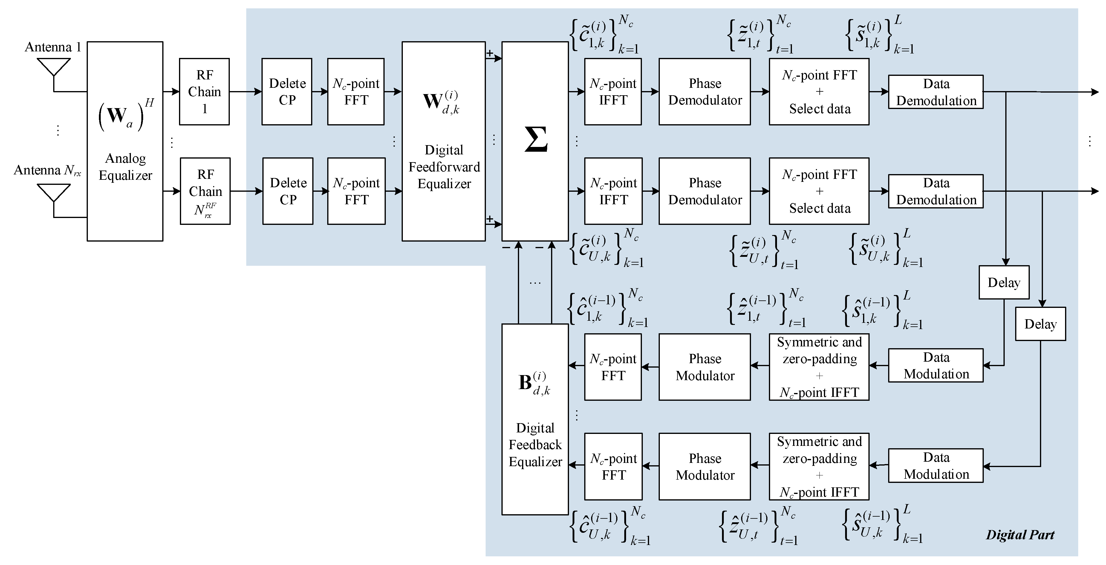
2.3. Receiver Characterization
The considered receiver structure is presented in
Figure 2. The received signal,
, at the
kth subcarrier, is given by:
where the vector
is the zero mean Gaussian noise with variance
. First, the analog part of the equalizer,
, with
is applied to the received signal. Then, it is performed the baseband processing, composed by
RF chains and the iterative digital multi-user equalizer. In its turn, a forward path, and a feedback path compose the iterative digital equalizer. In the feedfoward path, it is applied the digital linear filter
on each subcarrier
k, such that,
, where
and
is the maximum iteration number. Then, the samples
are moved to the time domain, where it is applied the phase demodulator obtaining the samples
. Finally, a
- point fast Fourier transform (FFT) and a selection operation are performed to obtain the soft estimates
and the corresponding hard estimates,
.
In the feedback path, the inverse processing is done, i.e., the data recovered from the forward path is again modulated in the symbols the Hermitian symmetric zero-padded data vector is made using the structure of (1), and it is applied a - point IFFT and the phase modulator. Finally, the resulting signal, , is filtered by the feedback equalizer matrix, , at kth subcarrier.
After all this processing, we obtain the processed received signal for iteration
i,
, expressed by:
3. Precoder and Equalizer Design
In this section, a low-complexity analog precoder, based only on average angles of departure (AoD), is presented. Then, the iterative hybrid analog-digital multi-user equalizer for CE-OFDM systems is derived. A decoupled transmitter-receiver optimization problem is assumed in this paper because the resulting joint optimization problem will be nonconvex, even without considering the analog part constraints, and is therefore, mathematically intractable [
40].
3.1. Analog Precoder
The aim of the analog precoder is to maximize the beamforming gain between each UT and the BS. To compute the analog precoder, let us consider:
where
is the normalized array response vector, which for ULA case is given by (5), and
, is the average AoD for
qth cluster of
uth user channel. Notice that by assuming only the knowledge of the average AoD we reduce the feedback information from the receiver to the transmitter, making our design more useful for practical applications. The analog precoder is obtained from the eigenvalue decomposition of correlation matrix
, i.e., we compute
. Therefore, the analog precoder vector of the
uth user is given by:
From Equation (9), we can see that the analog precoder selects the vector of
that corresponds to the largest eigenvalue of
and then projects its elements along the unit magnitude set; therefore, it points the beam along the dominant channel direction. The discrete transmitted baseband signal of the
uth user, at
kth subcarrier,
, is given by:
3.2. Hybrid Equalizer
In this section, we design the proposed analog-digital multi-user equalizer to efficiently remove both the multi-user and residual inter carrier interferences. In the following derivation, the closed-form iterative digital equalizer is firstly obtained as a function of the analog part of the equalizer, then, the analog part of the equalizer, which cannot be obtained iteratively, is derived assuming that the digital part will fully remove the interference. The analog part is composed by a set of vectors selected from a dictionary based on the receive array response matrix. Finally, the digital equalizer is iteratively computed using the analog fixed coefficients.
3.2.1. Design of Iterative Digital Equalizer
In this section we derive the digital part of the equalizer, which is composed by the feedforward,
, and feedback,
, coefficients. The hybrid equalizer is designed by minimizing the sum of the
of all subcarriers. Mathematically, the optimization problem may be formulated as:
where
is the equivalent channel, and
denotes the set of feasible analog coefficients. Considering that the entries of
are approximately Gaussian distributed, it can be proven that the input-output relationship between
and
,
is [
41]:
where
is the zero mean error, uncorrelated with
Considering (7) and (12) the
can be expressed as:
where
and
is a diagonal matrix whose
uth element gives a blockwise reliability measure of the estimates of
uth block, associated to the
ith iteration [
32]. The bit-error-rate (BER) for iteration
i, at receiver side, can be estimated by the semi-analytic BER approximation [
42], given by:
where
,
, for a
M-QAM constellation, and
denotes the Q-function.
is the mean square error on samples
, with
, at iteration
i.
First, let us calculate the digital feedback matrix,
, through the following optimization problem:
where
appears as a function of
and
. The problem (15) does not have any constraint (and it is convex), since
is independent of the constraints of (11). From Equation (13) and from the Karush–Kuhn–Tucker (KKT) conditions, i.e.,
, it can be proven that the digital feedback matrix is given by:
To compute the digital feedforward filter, we start by replacing Equation (16) in Equation (13), and obtain:
where
denotes a non-normalized version of full digital equalizer, i.e.,
with
given by Equation (A2). The formulation of problem and corresponding solution for the fully digital case is presented in the
Appendix A. As can be shown by Equation (17), the MSE can also be expressed as the difference between the hybrid and the full digital equalizer matrices.
Therefore, the optimization problem to compute the iterative digital feedforward equalizer is given by:
where Equation (18) is also a convex problem, since
is independent of constraint
. To calculate
as function of
, we can compute the associated Lagrangian of the problem (18) given by:
where the coefficients
are the Lagrange multipliers, and
, and make
Therefore, the solution of (18) is given by:
where
ensures the power constraint of (18) and it is given by:
The pseudo-code to compute the digital part is presented in the Algorithm 1. This pseudo-code uses the analog precoder matrix,
, as input, which is designed in the next section.
| Algorithm 1 Digital part of the equalizer |
| Input: |
| 1: |
| 2: |
| 3: for do |
| 4: |
| 5: |
| 6: Compute |
| 7: |
| 8: end for |
| 9: return , |
3.2.2. Design of Fixed Analog Feedforward Equalizer
In this section, the analog part of the hybrid equalizer is designed. From (11) and after obtaining the solution for
and
, we have the following optimization problem:
where the power constraint of (11) or (18) is not considered, since it is assured by
, given by Equation (21), computed in the digital feedforward equalizer. Since the analog part is computed in the first iteration, for simplicity, we removed the index
i, and then
corresponds to
.
The problem (22) is nonconvex because of the constraint
. Then, we propose a solution based on OMP algorithm, where a set of vectors is selected from
. We assume in this paper that
is composed by the set of receive array response vectors,
, presented in the channel model (4). The concatenated matrix with this set of vectors is
, where:
Let
be the equalizer vector of the
rth RF chain such that
and define
, where
. Then,
is given by:
for
. Replacing (24) in (17), the problem (22) simplifies to:
where
represents the dictionary defined by columns of
is the residue matrix, and
is the MSE using
r RF chains. Making
, we obtain:
Replacing Equation (27) in Equation (26), we obtain
where
. As mentioned, the analog part of equalizer should remain constant due to hardware constraints, thus, we need to fix the coefficients of matrix
to calculate
. As the number of iterations increases,
the estimates are more reliable, and the coefficients tend toward 1. Then, we fixed
for the analog part calculations. Therefore, from Equation (A5) we have
, and as
has magnitude
then we have
The first norm of Equation (28) does not depend on
while the second one is a correlation involving
. Therefore, we may use the second norm of Equation (28) as a metric to select the best entry of dictionary, i.e., Equation (25) is equivalent to the following optimization problem:
From Equation (29), the index vector,
, selected from
, is given by:
where
. The solution of Equation (29) is presented in the pseudo-code of Algorithm 2, where from Equation (A2) and
, we assume a non-normalized version of fully digital equalizer given by
We start by setting the analog equalizer as an empty matrix, because any vector was still selected. We also set the residue matrix as the trivial value,
. Then, the best column from the dictionary
is selected for the
rth RF chain, and the residue matrix is updated. The previous steps are repeated until
be selected, and the analog equalizer matrix is obtained.
| Algorithm 2 Analog part of equalizer |
| 1: = Empty Matrix |
| 2: |
| 3: for do |
| 4: |
| 5: |
| 6: |
| 7: |
| 8: end for |
| 9: return |
3.3. Complexity Analysis
In this section, the complexity of the proposed algorithms are evaluated. In Algorithm 1, the digital equalizer is computed using the inversion of a matrix, which results in a complexity . This inversion is repeated times, and then the total complexity of Algorithm 1 is
In the Algorithm 2, the metric of Equation (29) is tested for all elements of the codebook , composed by the vectors of . The product complexity of the matrix of size by a vector of size is . Then, the complexity of the metric evaluation is As these operations are repeated times, the complexity of the Algorithm 2 is Therefore, the total complexity computation of the proposed equalizer is
4. Performance Results
The main performance results of the proposed hybrid analog-digital multiuser equalizer, designed for CE-OFDM based systems, are shown in this section. The performance metric is the average
as a function of
, where
is the average bit energy, and
is the one-sided noise power spectral density. We assume that the signal transmitted power of all users is the same, such that,
, and then
. The quadrature phase shift keying (QPSK) modulation is adopted. For each UT, the wideband mmWave channel model defined in Equation (3) is considered and the parameters presented in
Table 1. At the receiver side, it is assumed a perfect synchronization and a perfect CSI knowledge. The main fixed simulation parameters are also presented in
Table 1, and it is assumed the worst case, i.e.,
since for
. The performance results were obtained by varying the modulation index,
, the number of users and of RF chains, of receive antennas,
The specific values for these parameters are indicated in the figures.
First, let us evaluate the impact of modulation index on the performance of proposed hybrid system. As we can see in
Figure 3, several values for
were tested, and the results for 1st and 4th iterations were compared. Cleary, there is an optimal value, which is approximately
. A deeper discussion about the impact of the modulation index in the system performance can be found in [
19]. Hereinafter, the results are obtained for
.
In
Figure 4, we compare the simulation results with the semi-analytic BER approximation in (14). We can see that the results are very close, then we conclude that
is approximately Gaussian distributed, and we confirm that the assumption made in Equation (12) was correct. We may also see that the performance gap from iteration 1 to iteration 2 is higher than from iteration 2 to iteration 4. This happens because most of the residual ISI and multiuser interference are removed from the 1st to the 2nd iteration. From the 2nd to the 4th iteration, the gain is smaller because most of the interference was already removed.
In
Figure 5 and
Figure 6, a comparison between the proposed iterative hybrid equalizer and the iterative fully digital one, for
and
was performed, respectively. All expressions of the hybrid case are valid for the full-digital case, assuming the number of RF chains are equal to the number of receive antennas. Therefore, for the fully digital case, only Algorithm 1 is used, assuming
. For
(
Figure 5), the gain of the proposed hybrid equalizer, from the 1st to 4th iteration, for a BER target of
, is 7.2 dB, and the penalties from hybrid to fully digital case are 7.1 dB and 2.7 dB, for iterations 1 and 4, respectively. For
(
Figure 6), the gain of the proposed hybrid equalizer, from the 1st to 4th iteration, for a BER target of
, is 4.4 dB, and the penalties from hybrid to fully digital case are 6.6 dB and 3.6 dB, for iterations 1 and 4, respectively. For both cases, the performances are closer for iteration 4 than for iteration 1, which means that the iterative approach is very interesting for hybrid systems.
A performance comparison for a different number of users (and of RF chains) can be seen in the
Figure 7. For iteration 1, we can see that the performance gets worse when the number of users increases. This happens because when the number of users increases, the interference level also increases, and the receiver does not have the ability to remove this interference only with a linear filter, i.e., with only one iteration. However, when the number of iteration increases, this interference is removed. Then, at iteration 4, the performance can even improve when the number of users increases, because we have more degrees of freedom at the digital part, since the number of RF chains also increases.
Finally, in the
Figure 8, we can see the performance for a different number of receive antennas. This figure proves that there is a gain when we only increase the complexity of analog part, in terms of number of antennas and phase shifters, keeping the same complexity for digital processing. Therefore, the analog part of proposed equalizer is very efficient to improve the system performance, proving that the hybrid analog-digital architecture is a very promising approach. The gain of proposed hybrid equalizer, from 1st to 4th iteration, for a BER target of
, decreases when the number of receive antennas increases. This happens because a higher level of interference is removed at the analog part, when we increase the number of antennas and phase shifters. At iteration 4, the gaps from
to
, and from
to
are 2.2 dB and 2.5 dB, respectively, which is a little less than the expected 3 dB, which is the expected for a typical full-digital system.
5. Conclusions
In this paper, we proposed an iterative hybrid multi-user equalizer for the uplink of broadband mmWave mMIMO CE-OFDM systems. Due to hardware constraints, the analog part of the equalizer is fixed over the iterations and subcarriers, while the digital equalizers are iterative and computed on a per subcarrier basis. These ones were designed by minimizing the sum of the MSE of all subcarriers. The user terminals employ a low complex analog precoder based on AoD.
The results showed that the proposed iterative multi-user equalizer is quite efficient to mitigate the ISI and the multi-user interference, achieving a BER performance closer to the fully digital counterpart. The results also show that by increasing the number of users (and of RF chains), the performance for iteration 4 also increases, which is a promising result for a realistic scenario with several users. Finally, when we increase the analog processing, keeping the same complexity for digital processing, the performance is improved, which proves that the analog part of proposed equalizer is very efficient to improve the overall system performance. Therefore, the proposed equalizer can be a good choice for practical broadband mmWave CE-OFDM systems employing mMIMO terminals.


 ,
, 


