Article

Cutting Blade Measurement of an Ultrasonic Cutting Machine Using Multi-Step Detection

1
School of Electronics Engineering, IT College, Kyungpook National University, 80, Daehak-ro, Buk-gu, Daegu 41566, Korea
2
Institute of Advanced Convergence Technology, Kyungpook National University, Daegu 41566, Korea
*
Authors to whom correspondence should be addressed.
Appl. Sci. 2019, 9(16), 3338; https://doi.org/10.3390/app9163338
Submission received: 5 July 2019 / Revised: 8 August 2019 / Accepted: 10 August 2019 / Published: 14 August 2019
(This article belongs to the Section Applied Industrial Technologies)

Abstract

:
An algorithm for measurement of the cutting blade of the ultrasonic vibration cutting machine used in an automation machine is proposed in this paper. The proposed algorithm, which is based upon a multi-step detection method, is developed for the accurate measurement of the cutting blade by exactly determining its rotation angle, length, and thickness. Instead of the commonly used Otsu method, we propose a new curvature-based adaptive binarization method, which provides more accurate details about the dimensions of the cutting blade. A region of interest containing the cutting blade from the acquired image is first extracted in the multi-step detection method, which is further processed to remove the noise, which increases the measurement reliability. An important feature of the proposed process is the restoration of the cutting blade’s tip data, which used to be lost during the fine noise-filtering process. The rotation angle and length are measured using the minimum rotated rectangle while the line fitting based upon the least square method is applied to increase the reliability of the thickness measurement. Experimental results validate the superiority of the proposed method over the conventional Otsu method.

Graphical Abstract

1. Introduction

With the development of ultrasonic cutting technology, an ultrasonic vibration cutting machine is used for the precise cutting of fabrics, rubber, thermoplastic foil, non-woven fabric, etc. In particular, cutting machines using ultrasonic vibration are capable of cutting very precisely without exerting any pressure on the objects in order to avoid any surface deformation. Ultrasonic vibration cutting also features very high cutting speeds and reduced cleaning costs, which has increased their demand for use in automation machines [1]. However, when the ultrasonic vibration cutting machine is used in connection with an automatic machine (such as robot arm), it is difficult to recognize the replacement cycle or the degree of wear and tear of the cutting blade [2]. This process results in inaccurate cutting of the object and material damage. For this reason, the development of an automation inspection system, which is based upon the machine vision system, is actively underway [3,4]. The machine vision system acquires images using a camera and then quantitatively judges [5] the degree of abrasion and warping/breakage of the cutting blade. In order to improve the productivity and reliability, machine vision inspection equipment is commonly used in actual practice. Recently, the machine vision has been actively deployed in research for the development of measurement systems for different applications. Measurement of the dimensions of an O-ring [5], detecting defects in a thin film transistor liquid crystal display (TFT-LCD) [6], measurement of the refractory bricks [7], and measuring the size of an automobile break pad [8] are the few areas benefited by the machine vision.
In general, various methods, like brightness information, shape information, pattern information, etc., are used for object recognition in the field of image processing. Among these methods of object detection, template matching and feature point detection are the techniques which have gained more attraction [5]. However, template matching detects an object by determining the similarity of the image with a reference image that is not adaptive to the change of the reference image, which consequently deteriorates the results. On the other hand, the feature extraction method uses the shape and color information of the object or the blob information of the object based on the binarization. The detection method using the shape and color information of the object is sensitive to the change of color depending on the illumination. If the shape of the object is not specified, it is difficult to define the feature of the shape. In the object detection method based on blob detection, it is difficult to find the target object when there are objects other than the object to be detected [9,10].
In this paper, we propose a machine vision-based image processing algorithm that measures the thickness and length of the cutting blade to detect its bending and fracture, and also measures the rotation angle of the cutting blade in order to check the operation of the robot-arm. The region of interest (ROI) is extracted from the cutting blade area of the original image. The binarization based on the curvature of the extracted image is performed by the proposed method. The background region is extracted and removed from the binarization image, which is followed by the removal of various noises included in the extracted image. In order to recover the information of the cutting blade’s tip, which was lost in the fine noise removal process, only the tip of the cutting blade is extracted again from the background-removed image by assigning a new ROI only for the tip of the cutting blade. The thickness, length, and rotation angle of the cutting blade are then measured for the restored image.
This paper is divided into two main sections. The first section contains information about the “cutting blade measurement system” while the second section is dedicated to the proposed “curvature-based binarization method”, which is further followed by the experimental results and discussion.

2. Cutting Blade Measurement System

2.1. System Configuration

The structure of the cutting blade measurement system used in the experiment is shown in Figure 1a while the cutting blade used in the actual experiment is shown in Figure 1b. The cutting blade measurement system is composed of a vision system, vision camera, back light unit (illumination), and an ultrasonic cutting device carrying robot arm. The position of interest where the measurement of cutting blade has to be performed is in between the vision camera and the back light unit as shown in Figure 1a. The camera and back light unit are placed in such a way that both face the measuring position. When the cutting blade reaches the measurement position through the robot arm, the image is acquired through the installed vision camera. The obtained image is then transmitted to the vision system for further processing.

2.2. Detection Algorithm

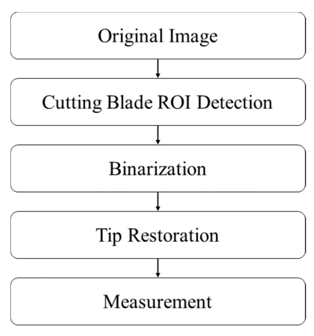
The flowchart of the proposed algorithm for the detection of the cutting blade of the ultrasonic cutting machine is shown in Figure 2.
The first step of the algorithm is the extraction of the ROI (which contains the cutting blade) from the original image, which was acquired using the vision camera. The second step is the detection of the peak curvature of the gray values that is used as the binarization standard, which is deployed to model the unwanted areas in the ROI as the background image, which are further removed by using the morphological filter. This background-removed image contains various fine noises, which are need to be removed using noise filtering for the accurate detection of the cutting blade. However, in this fine noise removal process, the data which contains the information about the tip of the cutting blade is also removed. The third step is to define a new ROI in the binary images before and after noise removal. This new ROI only encloses the area surrounding the tip of the cutting blade, which is then restored by comparing these two images. Finally, the rotation angle and the length of the cutting blade are measured by using the bounding box that is in contact with the outer line. In addition, the thickness of the cutting blade is also measured from the detected image by using the line fitting technique based on the least square method.

2.3. ROI Detection

The original image of the cutting blade contains various information which makes the accurate detection of the cutting blade rather difficult. The problem is addressed by defining a specific ROI which encloses only the cutting blade. The method of extracting the ROI is shown in Figure 3.
First, the S region of the original image is detected and then the pixel margin is added to extract the R region, which is the required ROI as shown in Figure 3a. In order to detect the S region, the binary image is obtained at the 128 gray value of the original image as shown in Figure 3b. By using the binary value of 128, it is possible to quickly grasp the position of the cutting blade. However, accurate measurement is not possible at this value. Using the line profile, the edge boundary of the cutting blade where the value changes from 255 to 0 is detected and set as the starting point of the cutting blade. Additionally, the boundary is defined as the end point where the gray value changes from 0 to 255 while having the expected cutting-edge thickness.
Then, the average of the x-coordinates of the detected boundaries are calculated to detect the region of interest, S. The region of interest, R, as shown in Figure 3c, is extracted from the original image of Figure 3a by adding the pixel margin to the detected region, S.

3. Curvature-Based Binarization Method

3.1. Image Binarization

The gray image needs to be converted into the binary image for accurate determination of the thickness and length of the cutting blade. The generally used Otsu method extracts the objects with similar brightness values using the image histogram by finding a value that maximizes the between-class variance [11]. This method works well under the assumption of bimodal images with implicitly uniform illumination; conversely, it is limited by many factors involving the small object size and the presence of a large amount of noise requiring image restoration [12]. When the designated image is composed of L gray-level pixels, where the number of pixels whose brightness value is i , i { 1 , , L } is f i , the total number of pixels in the image is the image is N , and the probability p i for such a pixel can be obtained as follows:
N = i = 1 L f i ,
p i = f i N .
On the basis of the pixels’ gray levels, the image can be divided into two classes, C 0 and C 1 , where the pixels with gray levels [ 1 , , k ] are in the class C 0 and the pixels with gray levels [ k + 1 , , L ] are in class C 1 . If the probability distribution of each class is called ω 0 and ω 1 , respectively, while the overall average of the original image is μ T , the threshold value of Otsu can be obtained by finding k * , which maximizes the distribution, σ B 2 ( k ) , between classes using Equations (3) and (4).
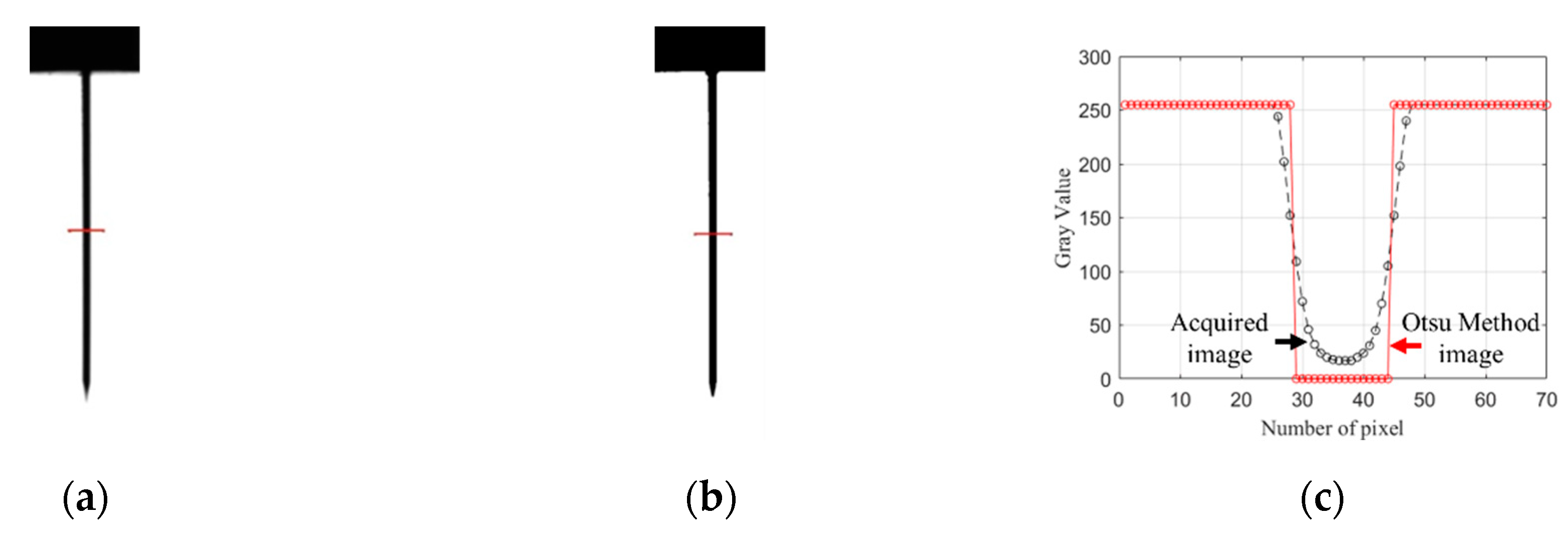
The ROIs of the captured image and the binary image by the Otsu method are shown in Figure 4a,b, respectively. A comparison between the gray levels of the input image and that obtained from the Otsu method along a smaller line segment at the same position in the ROI are provided in Figure 4c, which shows that due to the specific limits of binarization standard and diffraction of light, the Otsu method is unable to detect the exact thickness of the cutting blade:
σ B 2 ( k ) = [ μ T ω ( k ) μ ( k ) ] 2 ω ( k ) [ 1 ω ( k ) ] ,
σ B 2 ( k * ) = max σ B 2 ( k ) , 1 k L .
It is hard to divide the target accurately by defining the standard of binarization based upon the brightness value by using the Otsu method, which can be seen in the previous example. This phenomenon occurs due to the diffraction of light. The problem can, however, be addressed if the high curvature value position in the gray-level profile of the pixels is defined as the binarization reference. In this paper, we propose the curvature-based binarization method for accurate detection of the cutting blade used in the ultrasonic vibration cutting machine. The curvature value is calculated from the horizontal line profile in the ROI of the gray image. The first order and the second order derivatives of the gray value profile at the given reference position for the given pixel are expressed as Equations (5) and (6). Where P ( n ) is the gray level of the n -th position where P ( n ) is the first derivative, which represents the variation of the gray level, and w is the increment along the x axis and P ( n ) is the second order derivative of P ( n ) :
P ( n ) = P ( n + t ) P ( n t ) w ,
P ( n ) = ( P ( n ) ) .
The curvature, k ( n ) , can be expressed in terms of P ( n ) and P ( n ) as given in Equation (7):
k ( n ) = P ( n ) ( P ( n ) 2 + 1 ) 3 2 .
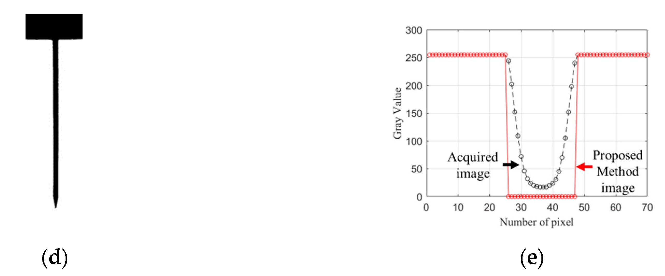
The result of the cutting blade detected by using the curvature-based image binarization method is given in Figure 5. Figure 5a shows the ROI image of the cutting blade obtained in the previous section. The line profile of the image of Figure 5a and the curvature value obtained using Equation (7) and its feature points using the extreme value of curvature are shown in Figure 5b,c, respectively. The binary image obtained using this method and a comparison of its gray value profile with the original image are shown in Figure 5d,e, respectively.
The original image of the cutting blade with the enlarged view of its tiny segment along a reference line is shown in Figure 6a. It can clearly be seen that the image is eroded due to the influence of the backlight illumination. The binary image obtained by the Otsu method with the enlarged view of its tiny segment along a reference line is shown in Figure 6b. It can clearly be seen that the portion of the cutting blade which had been eroded by illumination in the binarization process was removed, which results in the reduced thickness of the cutting blade, and leads to the inaccurate results. The binary image obtained by the method proposed in this paper with the enlarged view of its tiny segment along a reference line is shown in Figure 6c. It can clearly be seen that the portion of the cutting blade which had been eroded by illumination at the time of binarization was included, which provides an accurate thickness of the cutting blade. The comparison provided in Figure 6 verifies the accuracy of the proposed method in comparison to the Otsu method.

3.2. Background Extraction

In the binary image, the accurate extraction of the cutting blade area is difficult due to the existence of fine noise around the cutting blade and the mounting portion, which is used to fix the cutting blade. Therefore, for accurate detection of the cutting blade, the mounted part is also treated as the background, which is first extracted and then removed by using the morphological filter. The morphological filter includes erosion, dilation, opening, and closing computations. The opening and closing operations, γ ˜ ( f ) and ϕ ˜ ( f ) , can be given by using the Equation (8):
γ ˜ ( f ) ( x ) = δ ( ε ( f ) ) ( x ) ϕ ˜ ( f ) ( x ) = ε ( δ ( f ) ) ( x )
where ε ( f ) and δ ( f ) represent erosion and dilation, respectively [13]. In this paper, the background region is extracted by using the closing operation.
The cutting blade image obtained using the proposed binarization method is shown in Figure 7a. The background image extracted by using the closing operation is shown in Figure 7b. This image is also composed of the mounted portion of the cutting blade. The image of the cutting blade obtained by removing the background shown in Figure 7b from the image shown in Figure 7a is given in Figure 7c. Various fine noises exist in this image, which can lead to inaccurate measurement. An enlarged portion of the cutting blade near the mounted portion, which contains such fine noise, is shown in Figure 7d.
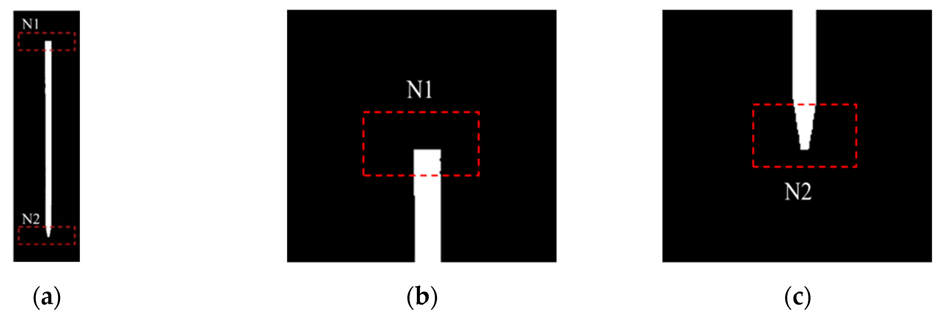
In order to remove these noises, the proposed method used the opening operation. The cutting blade image after removing the noise using the opening operation is shown in Figure 8a. Usually, the regions of the top and bottom parts (near the mounted portion and the near the tip) of the cutting blade are more immune to noise. The enlarged view of the regions, N 1 and N 2 , which enclose the mounted portion and the tip of the cutting blade are shown in Figure 8b,c, respectively. However, in this noise removal process, some data is lost in the N 2 region, which results in inaccurate information about the tip of the cutting blade. Some measures are needed to restore the lost tip data in order to secure the accurate cutting blade image.

3.3. Restoration of Lost Data

In this paper, we proposed a new technique that restores the data of the cutting blade’s tip which was lost during the fine noise filtering by comparing the region, N 2 , in two images. For this purpose, a similar ROI is defined in the two images (image before data loss Figure 7c and image after data loss Figure 8a and a comparison of these two ROI’s provides the lost data of tip, which is than restored). This process of lost tip data restoration is shown in Figure 9.
The ROI in the noise-removed image with the lost tip data is shown in Figure 9a. Two straight lines, a 1 a 2 and b 1 b 2 , are drawn, which circumscribe the cutting blade portion as shown in Figure 9b in the defined ROI. By knowing the coordinates of points a 1 ( x 1 , y 1 ) , a 2 ( x 2 , y 2 ) , the line can be further extended by using Equation (9). The same treatment is done for the points, b 1 and b 2 , and extend both lines to point c where they meet each other. The coordinates of point c can be determined in terms of the points, a 1 , a 2 , b 1 and b 2 , by using Equation (10):
y y 2 = y 2 y 1 x 2 x 1 ( x x 1 ) ,
( a 2 b 2 a 1 b 1 , a 1 a 2 b 2 a 1 b 1 + a 1 a 2 ) .
The area in the triangle a2b2c contains information about the lost data, which is to be restored by comparison of the pixels of two images as shown in Figure 9c. The region, A , in Figure 9c shows the noise-removed image, which remains unchanged during the lost tip data restoration operation. The region, B , on the other hand, shows the restored data of the cutting blade tip in Figure 9c, which was lost during noise removal process. The proposed technique results in accurate detection of the cutting blade without data loss.

3.4. Cutting Blade Rotation Angle and Length Measurement

The commonly used bounding box suffers from the disadvantage of non-consideration of the rotation angle of the object, which leads to inaccurate measurement of the length and thickness of the cutting blade. The problem is addressed in this paper by using the minimum rotated rectangle method to measure the angle and length of the cutting blade.
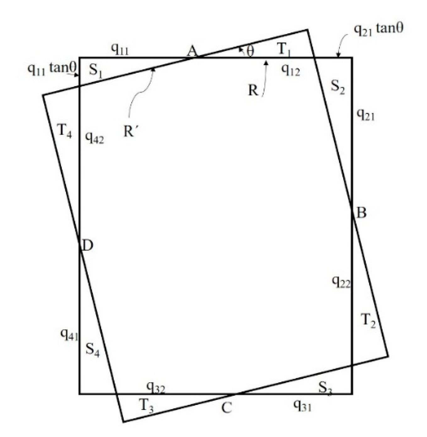
A rotated rectangular bounding box for finding the least circumscribed rectangle is shown in Figure 10.
The difference, Δ A , between the area of rectangle, R , and the area of rectangle, R , can be determined by using the following method described by Freeman et al. [14]:
Δ A = | i = 1 4 S i i = 1 4 T i | .
S i and T i can be given as follows:
S i = 1 2 ( q i , 2 q i + 1 , 1 tan θ ) 2 sin θ cos θ ,
T i = 1 2 q i , 1 2 tan θ .
By substituting Equations (12) and (13) in Equation (11) and simplifying:
Δ A = sin 2 θ i = 1 4 q i , 2 q i + 1 , 1 + 1 2 sin θ cos θ [ i = 1 4 q i , 1 2 i = 1 4 q i , 2 2 ] ,
Δ A = N 1 + N 2 [ i = 1 4 q i , 1 2 i = 1 4 q i , 2 2 ] ,
where N 1 and N 2 are both positive quantities. Δ A is the amount by which the area of R is less than that of R [15,16,17].
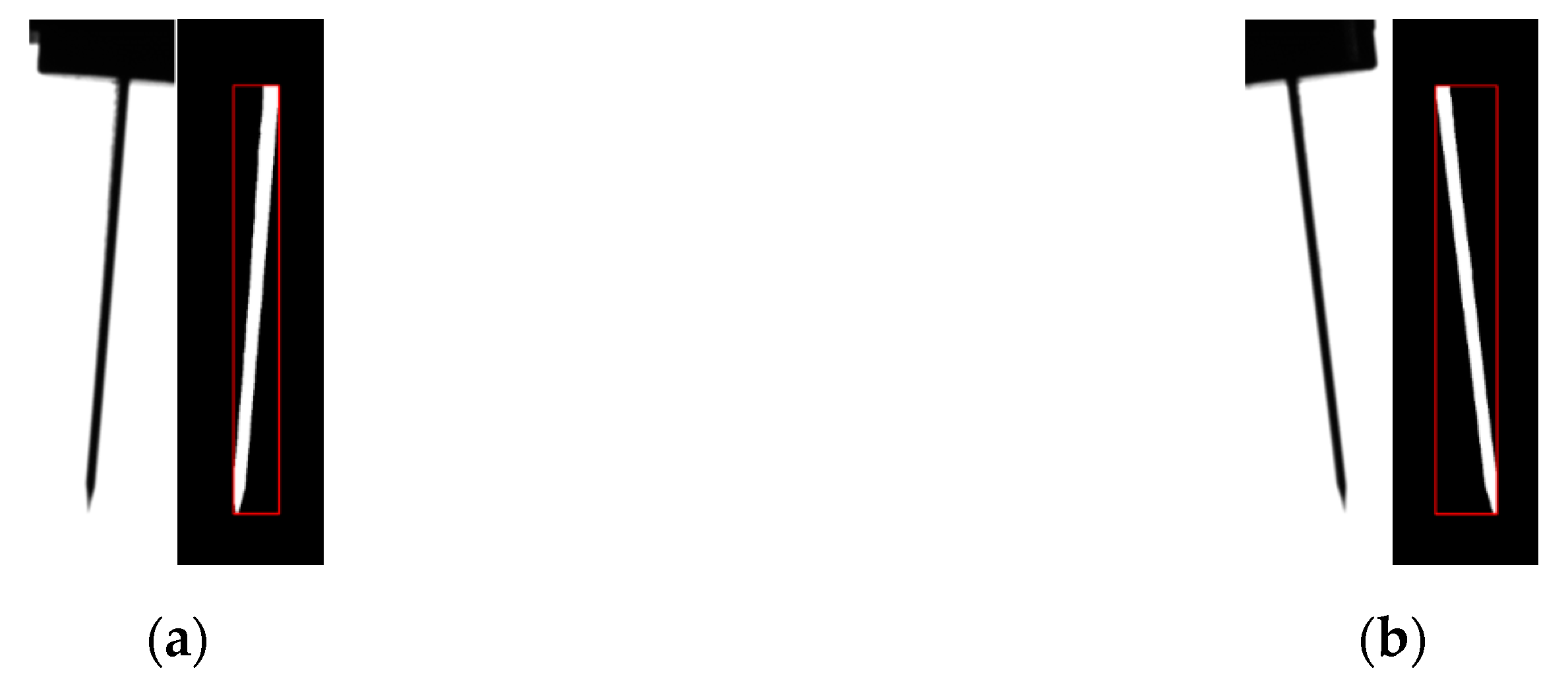
The input image for the detection of the cutting blade area is shown in Figure 11a. A commonly used rectangular bounding box for the detection of the cutting blade is shown in Figure 11b. The cutting blade does not lie in the perpendicular plane rather it is rotated by some angle, which makes the measurements obtained through the commonly used rectangle inaccurate and unreliable due to the reduced length and increased thickness of the cutting blade. The measurements can be accurate only if the rectangular bounding box is also rotated by a similar angle to that of the cutting blade. A rotating rectangular bounding box that accurately measures the length of the cutting blade and the angle of rotation by means of the least sized bounding box that considers the rotation angle of the cutting blade is shown in Figure 11c.
The thickness and length of the cutting blade can also be measured by using the minimum rotated rectangle method. However, if some fine noise is present along the edges of the cutting blade, the outermost boundary of the bounding box is unable to exclude such noise, which results in the slightly inaccurate thickness measurement. The problem is resolved by using the optimized line fitting algorithms for thickness measurement.

3.5. Cutting Blade Thickness Measurement

To minimize the impact of this fine noise which is present along the edges of the rotated cutting blade, the thickness of the cutting blade was measured by dividing the left and right sides with respect to the center coordinates of the cutting blade to find the optimized straight lines for each of its edge as shown in Figure 12.
The line fitting was performed by using the least square method, which is an approximation technique to solve the equations. For the n number of points with x i dependent variables and y i independent variables with ( 1 i n ) , a model function, f ( x , β ) , can be defined, where β is a vector with β = ( β 0 , β 1 , , β k ) , then the equation for least square method can be given as follows:
N = i ( y i f ( x i , β ) ) 2 .
The distance, d , between a point ( x 1 , y 1 ) on the one straight line and another straight line, a x + b x + c = 0 , can be calculated using the following equation:
d = | a x 1 + b y 1 + c | a 2 + b 2 ,
where d corresponds to the thickness of the cutting blade.

3.6. Abnormalities’ Inspection in the Cutting Blade

Using the proposed algorithm, the rotation angle, thickness, and length of the cutting edge of the ultrasonic cutting machine can be measured to identify any abnormality or the absence of the cutting blade and robot arm movements. An alarm is triggered on the equipment for the inspector to take action in case of an automatic equipment malfunction, which may prevent damage to the original material or equipment. If the length or thickness of the measured cutting blade differs from the actual value, it can determine whether the cutting blade is broken or bent. In the case of a robot arm, it shall always be in the set position; however, if the turning angle of the cutting blade is out of range, it is possible to determine that the robot arm is abnormal, or the cutting blade is in poor condition. A cutting blade that was detected by using the proposed method is shown in Figure 13. This detected image has severe left and right rotation angles as shown in Figure 13a,b, respectively. Thus, it was confirmed that the proposed method can detect the cutting blade with large rotational angles in a range of 0° to 90°.

4. Experimental Results and Discussion

The images of the cutting blade of the ultrasonic cutting machine which were used in this paper were acquired using a 5 MP mono camera made by Basler. The acquired images were gray image with 2448 × 2048 pixels. The images were processed by using the proposed method at a PC with Intel Core i5 CPU and 16 GB RAM (Intel Corporation, Santa Clara, CA, USA).
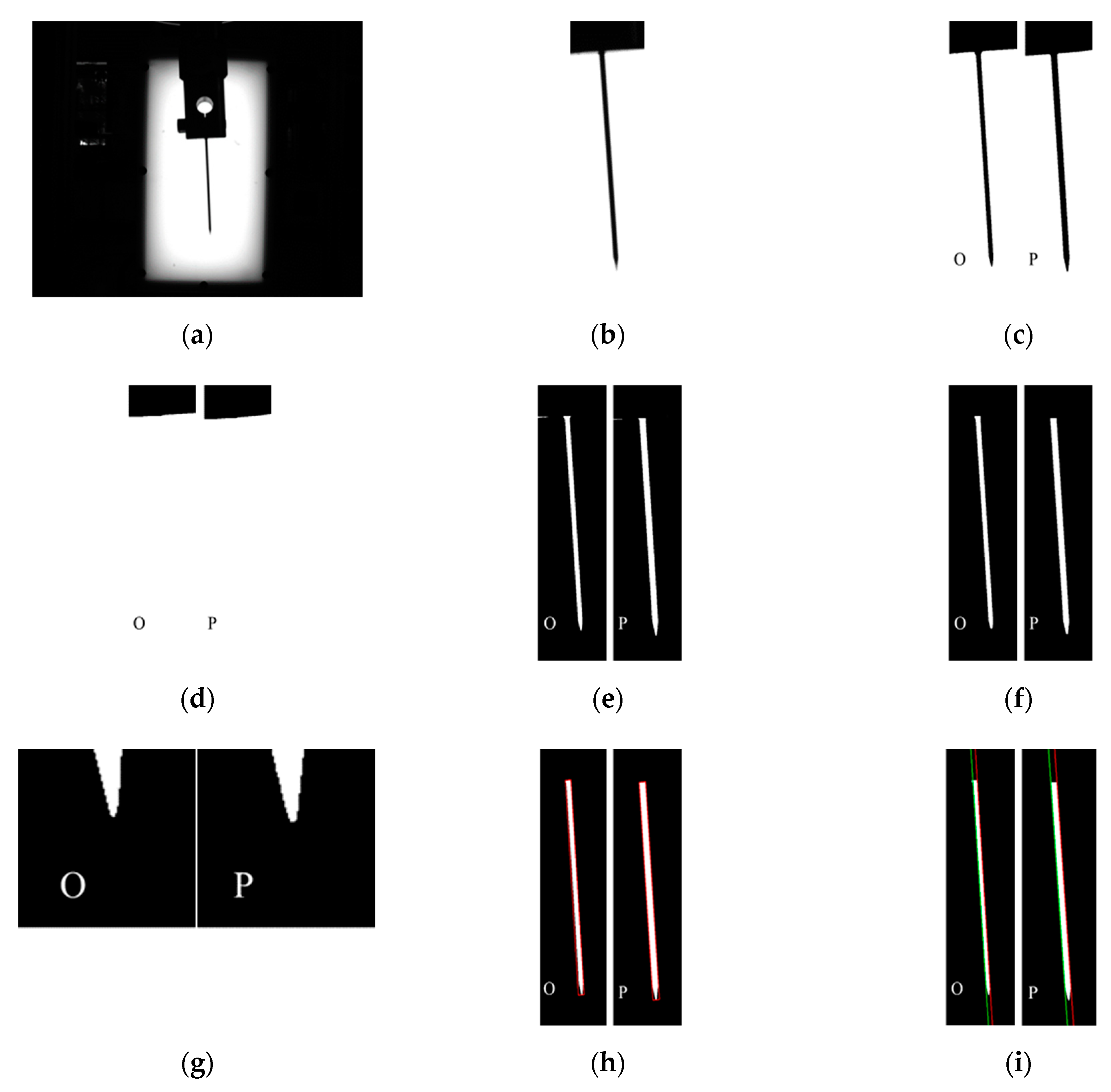
A step-by-step comparison of the cutting-edge measurement algorithms of the commonly used Otsu method (O) and the proposed curvature-based binarization method (P) is given in Figure 14. The original image and the ROI image of the cutting blade are shown in Figure 14a,b, respectively. The binary images obtained by the existing Otsu method and the proposed method are shown in Figure 14c. The modeling of mounting portion as the background area in the binary image and the detected cutting blade images after removing the mounted portion are shown in Figure 14d,e, respectively. The images after noise removal by using the morphological filter and the images after tip restoration (which was lost during the noise removal process) as obtained by the two methods are shown in Figure 14f,g, respectively.
The images for the detection of the length and rotation angle of the cutting blade by using the minimum rotated rectangle and the images for the detection of the thickness of the cutting blade by using the least square method-based line fitting technique for the two methods are shown in Figure 14h,i, respectively.
The performance comparison of the Otsu method and proposed curvature-based binarization method is provided in Table 1.
The comparison provided in Table 1 verifies that the results obtained by using the proposed curvature-based binarization method are more accurate and closer to the actual measurements in comparison to the Otsu method. The mean error in thickness measurement is 0.16 mm by the Otsu method while it is within 0.004 mm using the proposed method. Similarly, the mean error in length measurement is 0.3 mm by the Otsu method while it is within 0.02 mm using the proposed method.

5. Conclusions

In this paper, a machine vision-based measurement system was proposed for accurate measurement of the rotated angle, length, and thickness of the cutting blade of an ultrasonic cutting machine. A multi-step detection algorithm was proposed to designate a region of interest in the captured image for the detection of the cutting blade. The binarization of the designated ROI of the image was performed by proposing a curvature-based adaptive binarization method instead of the commonly used Otsu method. The mounted portion of the cutting blade was also modeled as the background area and was removed using morphological computation from the binary image for accurate detection of the cutting blade. Then, the morphological filter was also used to remove the remaining fine noise from the background-removed image. The tip data of the cutting blade, which was lost in the noise removal process, was restored by defining the new ROI around the tip area of the cutting blade in the images before and after the noise removal. Measurement error introduced due to the malfunctioning of the robot arm was addressed by using the minimum rotated rectangle method for the measurement of the rotated angle and length of the cutting blade while the least square line fitting method was used to measure the thickness of the cutting blade accurately.
The measurement error in the thickness and length of the cutting blade with different rotation angles of the proposed curvature-based binarization method was found to be considerably lower than that of the Otsu method.

Author Contributions

T.-G.K., B.-J.Y. and H.D.K. conceived and designed the experiments; T.-G.K. performed the experiments; T.-G.K., B.-J.Y. and H.D.K. analyzed the data; T.-G.K. and S.F.A. contributed analysis tools; T.-G.K. and S.F.A. wrote the paper.

Acknowledgments

This research was financially supported by the industrial infrastructure program of Ministry of Trade Industry and Energy Republic of Korea (Establishment of infra-structure for laser industry support). This research was supported by Basic Science Research Program through the National Research Foundation of Korea (NRF) funded by the Ministry of Education (NRF-2018R1D1A1B07040457).

Conflicts of Interest

The authors declare no conflict of interest.

References

  1. Seo, J.S.; Lee, Y.J.; Kim, J.W.; Park, D.S. Design Improvement and Performance Evaluation of 20kHz Horn for Ultrasonic Cutting. J. Korean Soc. Manuf. Process Eng. 2013, 12, 135–140. [Google Scholar]
  2. Ji, S.; Yuan, J.; Wan, Y.; Zhang, X.; Bao, G.; Zhang, L.; Zhang, L. Method of monitoring wearing and breakage states of cutting tools based on Mahalanobis distance features. J. Mater. Process. Technol. 2002, 129, 114–117. [Google Scholar] [CrossRef]
  3. Furferi, R.; Governi, L.; Puggelli, L.; Servi, M.; Volpe, Y. Machine Vision System for Counting Small Metal Parts in Electro-Deposition Industry. Appl. Sci. 2019, 9, 2418. [Google Scholar] [CrossRef]
  4. Wen, S.; Chen, Z.; Li, C. Vision-Based Surface Inspection System for Bearing Rollers Using Convolutional Neural Networks. Appl. Sci. 2018, 8, 2565. [Google Scholar] [CrossRef]
  5. Jung, Y.; Park, K.-H. O-ring Size Measurement Based on a Small Machine Vision Inspection Equipment. J. Korea Ind. Inf. Syst. Res. 2014, 19, 41–52. [Google Scholar] [Green Version]
  6. Lee, J.-J.; Lee, K.-H.; Chung, C.-D.; Park, K.-H.; Park, Y.-B.; Lee, B.-G. Pattern Elimination Method Based on Perspective Transform for Defect Detection of TFT-LCD. J. Korea Multimed. Soc. 2012, 15, 784–793. [Google Scholar] [CrossRef] [Green Version]
  7. He, J.; Shi, L.; Xiao, J.; Cheng, J.; Zhu, Y. Size Detection of Firebricks Based on Machine Vision Technology. In Proceedings of the 2010 International Conference on Measuring Technology and Mechatronics Automation, Changsha, China, 13–14 March 2010; pp. 394–397. [Google Scholar]
  8. Xiang, R.; He, W.; Zhang, X.; Wang, D.; Shan, Y. Size measurement based on a two camera machine vision system for the bayonets of automobile brake pads. J. Int. Meas. Confed. 2018, 122, 106–116. [Google Scholar] [CrossRef]
  9. Choi, H.H.; Yun, B.J. Contrast Enhancement for the Captured Image by Estimating Local Illumination. Opt. Rev. 2011, 18, 389–393. [Google Scholar] [CrossRef]
  10. Lee, H.Y.; Kim, T.H.; Park, K.H. Target Extraction in Forward-Looking Infrared Images Using Fuzzy Thresholding via Local Region Analysis. Opt. Rev. 2011, 18, 383–388. [Google Scholar] [CrossRef]
  11. Otsu, N. A Threshold Selection Method from Gray Level Histograms. IEEE Trans. Syst. Man Cybern. 1979, 9, 62–66. [Google Scholar] [CrossRef]
  12. Boccardi, S.; Carlomagno, G.M.; Simeoli, G.; Russo, P.; Meola, C. Evaluation of impact-affected areas of glass fibre thermoplastic composites from thermographic images. Meas. Sci. Technol. 2016, 27, 075602. [Google Scholar] [CrossRef]
  13. Kim, T.-H.; Kim, S.-W.; Ryu, C.-H.; Yun, B.-J.; Kim, J.-H.; Choi, B.-J.; Park, K.-H. ECG Signal Compression using Feature Points based on Curvature. J. Korea Inst. Intell. Syst. 2010, 20, 624–630. [Google Scholar] [CrossRef]
  14. Lamiroy, B.; Gaucher, O.; Fritz, L. Robust Circle Detection. In Proceedings of the 9th International Conference on Document Analysis and Recognition, Parana, Brazil, 23–26 September 2007; pp. 526–530. [Google Scholar]
  15. Freeman, H.; Shapira, R. Determining the Minimum-Area Encasing Rectangle for an Arbitrary Closed Curve. Commun. ACM 1974, 18, 409–413. [Google Scholar] [CrossRef]
  16. Fischler, M.A.; Bolles, R.C. Random Sample Consensus: A Paradigm for Model Fitting with Applications to Image Analysis and Automated Cartography. Commun. ACM 1981, 24, 381–395. [Google Scholar] [CrossRef]
  17. Lei, Z.; Gao, J.; Wang, Z. Size Measurement Technology of Seals. In Proceedings of the 2010 3rd International Conference on Computer Science and Information Technology, Chengdu, China, 9–11 July 2010; pp. 222–225. [Google Scholar]
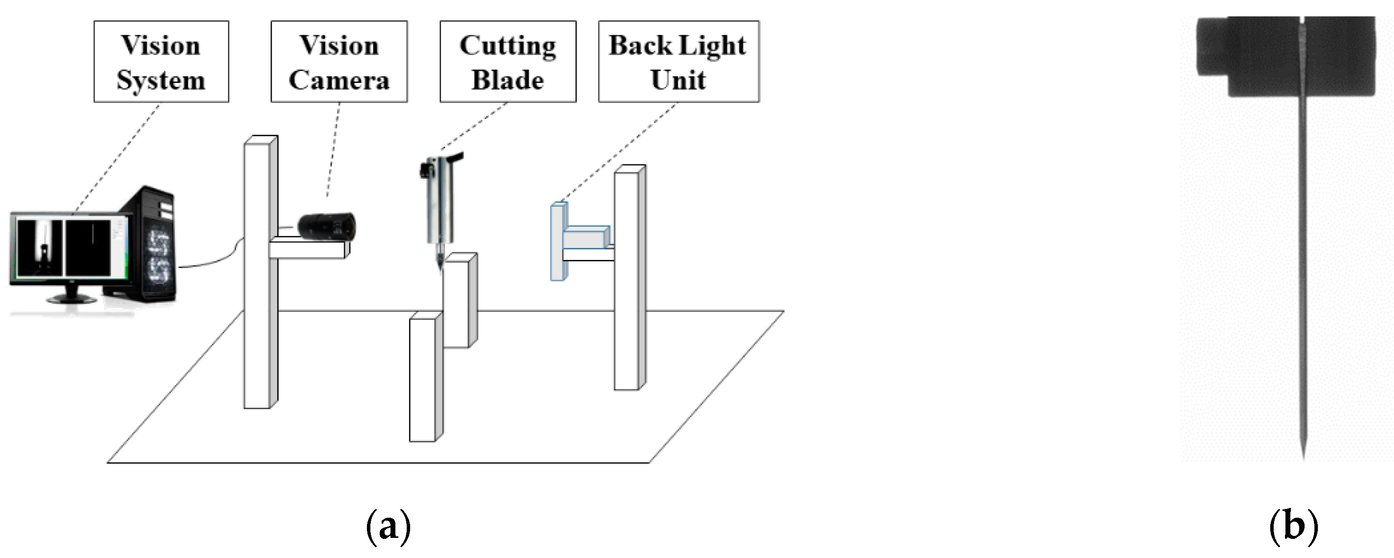
Figure 1. (a) Cutting blade measurement system; (b) cutting blade.
Applsci 09 03338 g001
Figure 2. Flowchart for the cutting blade detection algorithm. ROI: region of interest.
Applsci 09 03338 g002
Figure 3. (a) Original image of the cutting blade; (b) binary image; (c) ROI image.
Applsci 09 03338 g003
Figure 4. (a) ROI of the acquired image; (b) ROI of the Otsu method-based binary image; (c) comparison of the gray values of two images along same line profile.
Applsci 09 03338 g004
Figure 5. (a) Acquired image; (b) gray values line profile; (c) curvature values line profile; (d) proposed binary image; (e) comparison of the gray values of the acquired and binary images along the defined line profile.
Applsci 09 03338 g005aApplsci 09 03338 g005b
Figure 6. Images of the tiny segments of the cutting blade for thickness comparison for (a) the acquired; (b) Otsu method; and (c) proposed method.
Applsci 09 03338 g006
Figure 7. Cutting blade detection using the morphological filter. (a) Binary image; (b) background region modeling; (c) background removed image; (d) enlarged view of the image with fine noise.
Applsci 09 03338 g007
Figure 8. (a) Fine noise removed image of the cutting blade; (b) enlarged view of the mounted portion; (c) enlarged view of the tip showing a loss of data.
Applsci 09 03338 g008
Figure 9. Lost tip data restoration process. (a) ROI assignment to the morphological filtered image; (b) boundary mapping using straight lines; (c) restored tip data image.
Applsci 09 03338 g009
Figure 10. Formation of rectangle R by edge rotation.
Applsci 09 03338 g010
Figure 11. Detection of rotated cutting blade. (a) Acquired image; (b) generalized bounding box used for image detection; (c) minimum rotated rectangle bounding box for image detection.
Applsci 09 03338 g011
Figure 12. Least square method-based line fitting image of the cutting blade for accurate thickness measurement.
Applsci 09 03338 g012
Figure 13. The large rotational images. (a) Left rotated; (b) right rotated.
Applsci 09 03338 g013
Figure 14. Comparison of the cutting blade detection algorithms. (a) Acquired image; (b) extracted ROI; (c) binary images; (d) background modeling images; (e) background removed images; (f) noise filtered images; (g) ROI detection images for tip restoration; (h) minimum rotated rectangular bounding box images; (i) line fitting images.
Applsci 09 03338 g014
Table 1. A performance comparison between the Otsu method and the proposed curvature-based binarization method for the cutting blade dimensions’ measurement.
OriginalThickness0.6 mm
Length25 mm
Real AngleMeasured AngleOtsu Method [mm]Proposal Method [mm]
ThicknessLengthThicknessLength
0.429024.64000.600624.9550
2.20°2.186°0.457324.70710.600224.9889
3.40°3.367°0.442524.73780.613825.0209
−2.4°−2.444°0.428624.68430.600024.9585
Mean0.439324.69230.603624.9808
Standard deviation0.000180.001690.000040.00094