Article

Heuristic Techniques for the Design of Steel-Concrete Composite Pedestrian Bridges

by
Víctor Yepes
1,
Manuel Dasí-Gil
1,
David Martínez-Muñoz
1,
Vicente J. López-Desfilis
2 and
Jose V. Martí
1,*
1
Institute of Concrete Science and Technology (ICITECH), Universitat Politècnica de València, 46022 Valencia, Spain
2
Department. of Continuous Medium Mechanics and Theory of Structures, Universitat Politècnica de València, 46022 Valencia, Spain
*
Author to whom correspondence should be addressed.
Appl. Sci. 2019, 9(16), 3253; https://doi.org/10.3390/app9163253
Submission received: 5 June 2019 / Revised: 29 July 2019 / Accepted: 4 August 2019 / Published: 9 August 2019
(This article belongs to the Section Civil Engineering)

Abstract

:
The objective of this work was to apply heuristic optimization techniques to a steel-concrete composite pedestrian bridge, modeled like a beam on two supports. A program has been developed in Fortran programming language, capable of generating pedestrian bridges, checking them, and evaluating their cost. The following algorithms were implemented: descent local search (DLS), a hybrid simulated annealing with a mutation operator (SAMO2), and a glow-worms swarm optimization (GSO) in two variants. The first one only considers the GSO and the second combines GSO and DLS, applying the DSL heuristic to the best solutions obtained by the GSO. The results were compared according to the lowest cost. The GSO and DLS algorithms combined obtained the best results in terms of cost. Furthermore, a comparison between the CO2 emissions associated with the amount of materials obtained by every heuristic technique and the original design solution were studied. Finally, a parametric study was carried out according to the span length of the pedestrian bridge.

1. Introduction

Nowadays, society’s concern about the impact of activities is rising, not only their economic influence, but also the environmental impact. The construction sector is one of the most carbon intensive industries [1] due to the need for large amounts of materials and, henceforth, large amounts of natural resources. Therefore, researchers are investigating how to achieve cost efficient and environmentally sustainable processes for the construction industry. The term sustainable development was introduced for the first time by the Brundtland Commission, defining it as, “development that meets the needs of the present without compromising the ability of future generations to meet their own needs” [2]. Since then, countries have been raising awareness about the compromise to the future generations, modifying their policies and demanding cheaper, ecofriendly constructions, without forgetting their safety and durability. In essence, the demands of the governments are to reach solutions that reduce their impact on the three main pillars: the economy, the environment, and society.
These demands translate into restrictions for constructors and designer. The former need to carry out the constructions with new strategies to improve sustainability, while the designers have to conceive their projects in a cheaper, ecofriendly way. This means profiting the materials and taking maximum advantage of their characteristics, and maintaining durability and safety.
The traditional recommendation for the designers is to take a starting point for their designs. Furthermore, there are lots of strict codes and regulations to ensure the safe and reliability of constructions, mostly on the structure field. There are many codes, which define bridge loads [3] and concrete, steel, and composite bridge design [4,5,6]. In the same way, the European Committee for Standardization (CEN) has advertised regulations related to structural bridge design [7,8,9] as has the American Association of State Highway and Transportation Officials (AASHTO) [10]. In addition, authors have been working to provide proper box-girder bridge designs [11]. This search for optimal structures has led researchers to search for new forms of design, minimizing structural weight [12] and economic cost [13].
Since the first relevant works carried out in the field of structural optimization [14,15], the interest in the application of these techniques has grown a great deal, due to the different structural typologies studied (steel structures [16], reinforced or pre-stressed concrete structures [17,18], or composite structures [19,20,21,22,23,24]), as well as for the methods and algorithms used [25,26]. However, researchers have focused, to a large extent, on the cost optimization of these types of structures. Some researchers have stated that there is a relationship between the cost and environmental optimization, and cost optimization is a good approach for the environmental one [27].
Optimization looks to find the values of the parameters that define the problem that allow us to find the optimal solution. In the structural field, the problems tend to have too many variables to analyze all the possible solutions. Therefore, the use of approximate methods that allow us to reach optimal solutions have been studied. Research about heuristics and metaheuristics has been performed recently [28], such as neural networks [29], Hybrid Harmony Search [30], genetic algorithms [31,32], or simulated annealing [25,26]. Other authors have applied accelerated optimization methods, like kriging [33], allowing to simplify the main structural problems.
Some researchers have already applied the multi-criteria optimization for bridge design [34], considering other factors, besides the cost, like the security of the infrastructure and the CO2 emissions [27], the embodied energy [35], or the lifetime reliability [36]. However, these multi-criteria methods have not been applied to composite bridges. Other researchers, such Penadés-Plà et al. [37], have done a review of multi-criteria decision-making methods to evaluate sustainable bridge designs. Nevertheless, if we focused on composite bridges there is a lack of knowledge.
In recent years, databases measuring the environmental impact of materials have been elaborated, because of the importance of incorporating the design criteria to consider the impact on CO2 emissions [38,39,40]. Many researchers, such as Yepes et al. [41] and Molina-Moreno et al. [42], have used these databases to study the difference between the cost and the CO2 emission optimization for reinforced concrete (RC) structures.
The objective of this research was to study the differences between three heuristic optimization techniques applied to a steel-concrete composite pedestrian bridge. Furthermore, the differences between the CO2 emissions associated with the material amounts obtained from each heuristic were analyzed and compared with the original structural design. Finally, a parametric study, according to the span length, was performed.

2. Optimization Problem Definition

The problem proposed in this study is a single-objective optimization of a composite pedestrian bridge. To reach this purpose, a program that determined the optimum values of the variables was created. The objective was to minimize the objective function associated with the cost (1), satisfying the constraints imposed on the problem, represented by the Equation (2):
C ( x ) = i = 1 r c p i · m i ( x ) ,
  G j ( x ) 0 ,  
where vector x contains the design variables. To adjust the variables to real cases, these are discrete. The total cost objective function is given in Equation (1), where pi is the prices of every construction unit and mi the measurements obtained by the design variables. For example, for a random structure, the vector x would contain the design variables of that random structure, mi would contain the amount of materials associated with these variables, and these measurements, multiplied by their unit prices (pi), result in the total cost of the structure.
The values of cost for each variable contains the materials, labor and machinery. Because of the characteristics of the construction materials, the maintenance was not taken into account in this study. The construction place assumed in this paper was Valencia. The construction units included in this study (rc) were the volume of concrete, the amount of reinforcement steel, the amount of rolled steel, and the amount of shear-connector’s steel.
The unit prices of the materials were taken from the price table of the College of Civil Engineers of the Valencian Community for the year 2012. Furthermore, the CO2 emissions for each construction unit were obtained from Molina-Moreno et al. [42]. The data of rolled steel and shear-connector steel were taken to the BEDEC ITEC database of the Institute of Construction Technology of Catalonia [40]. Table 1 contains all the data on costs and CO2 emissions considered in this work.

2.1. Design Variables

The structural solution was defined by the parameters and variables, the fixed and variable data, respectively. In this work, the objective was to obtain an optimum steel-concrete composite pedestrian bridge with a box-girder cross section of 38 m of span length, modeled like a beam on two supports. The parameters are defined in Table 2. These values were considered fixed for the optimization. The construction was carried out on the ground and then large tonnage cranes lifted the structure. This constructive process made it possible to leverage the materials, because the steel and concrete deflection beginnings were the same when the structure was put into service.
Figure 1 shows the deck cross section geometrical variables and the reinforcement. Table 3 shows the limits defined for all the variables considered in this problem. The section is formed by two main elements, one the one hand, the steel beam conformed to steel sheets, welded and bolstered with longitudinal and transversal stiffeners. On the other hand, a reinforced concrete slab placed in the top of the steel beam and connected to this element by steel shear-connectors. Optimization variables were discrete, to bring the problem into line with reality. It was noted that some dimensions used may not have been practical, but allowed the algorithm to visit feasible intermediate solutions to find better optimal solutions. The total dimension of the problem was 1.67 × 1027 possible solutions, because of this, the complete evaluation of the problem was unapproachable. The problem optimization was carried out by heuristic techniques.

2.2. Structural Analysis and Constraints

The structure was analyzed like a linear element. The model of the structure considered the shear deformation and the effective flange width [6]. To obtain the stresses of the structure to check regulations and recommendations constraints, a Fortran language program was implemented. This program calculated the stresses in two sections: mid span and supports. In this structure, the highest stresses occurred in these areas. Prior to the verifying limit states, the program needed to calculate stress envelopes due to the loads. This program evaluated the stress envelopes due to a uniform load of 5 kN/m2 and the deck self-weight, including the bridge railing and asphalt (see Table 2). Note that the thermal gradient [5] and the differential settling in each support were also taken into account. The model implemented obtained the beam stresses and the transversal section tensions to assess the structural design validity.
Once the stresses were obtained, a structural integrity analysis was performed. The ultimate limit states (ULS) assessed the capacity of the structure against the flexure, shear, torsion, and the combination of the stresses. It further considered the minimum reinforcements to resist the stresses and the examination of the geometrical conditions. To evaluate the structural capacity, the regulations employed to obtain the equations that allow the verification of the pedestrian bridge have been the Spanish code on structural concrete [4], the Spanish recommendations for composite road bridge project [6], and the code on the actions for the design of road bridges [3]. The serviceability limit states (SLS) assessed the capacity of the structure to continue its service. The ULS considered in this study were: bending, shear, torsion, shear–torsion interaction, and the stiffeners verification. It must be taken into account that once the variables that define a frame solution have been chosen, then geometry, the materials, and the passive reinforcement are defined. It should be noted that no attempt has been made to calculate the reinforcement in such a way as to comply with common design rules. Such common design procedures follow a conventional order for obtaining reinforcement bars from flexural ULS, and then checking the SLS and redefining if required. While this order is effective, it ignores other possibilities that heuristic search algorithms do not oversee. The seismic verifications are not necessary due to the small value of the calculus acceleration for the location of the constructions. On the other side, the SLS assessed were: deflections, vibrations, cracking, and web deformation. The vibration limit state was verified in accordance with the restrictions for footbridges [4]. The SLS of cracking included compliance with limitations of the crack width for existing durability conditions. With respect to deflection, the instantaneous and time-dependent deflection was limited to 1/500th of the main span length for the characteristic combination [4], and the frequent value for the live loads was limited to 1/1200th of the main span length [5]. Concrete and steel fatigue were not considered, as this ultimate limit state is rarely checked in pedestrian bridges. In addition, the recommendations indicated in the specialized bibliography [43,44,45] were considered.
The modulus implemented compared the structure model values with the values obtained from the regulations equations. This modulus verified the demands of the safety, as well as those relating to the aptitude for service requirement. Therefore, the limit states and the geometrical and constructability requirements must be guaranteed. The ULS checked that the ultimate load effects were lower than the resistance of the structure, as seen in Equation (3):
R U S u ,
where Ru is the ultimate response of the structure and Su the ultimate load effects. For instance, the ULS of the shear and torsion interaction reduced the shear resistance due to the effect of the torsion. The SLS covers the requirements of functionality, comfort, and aspect (Equation (4)):
C s E s ,
where Cs is the permitted value of the serviceability limit and Es is the value obtained from the model produced by the SLS actions.

3. Applied Heuristic Search Methods

3.1. Descent Local Search

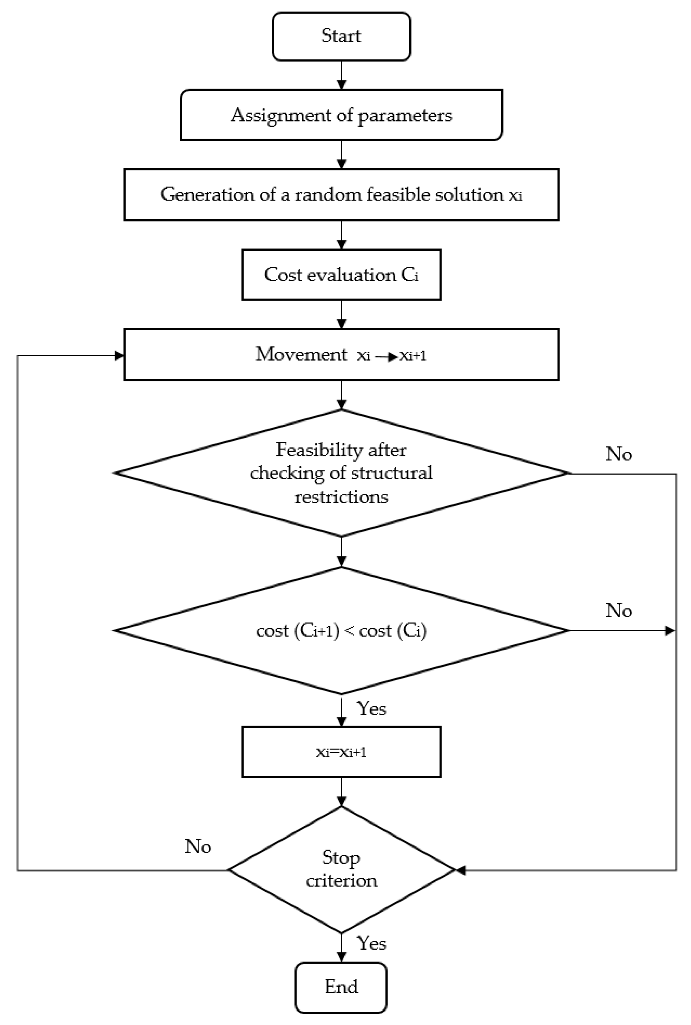
This algorithm (Figure 2) begins by obtaining a random initial solution. Then, a small movement is produced in randomly chosen variables, increasing or decreasing them by a unit step. The algorithm obtains the cost and the evaluation modulus check if the alternative fulfils the constraints. If the cost of the working solution is lower than the first and the new solution fulfills the restrictions, then it replaces the previous one. This process is continued until no better solutions are found, after a certain number of iterations.
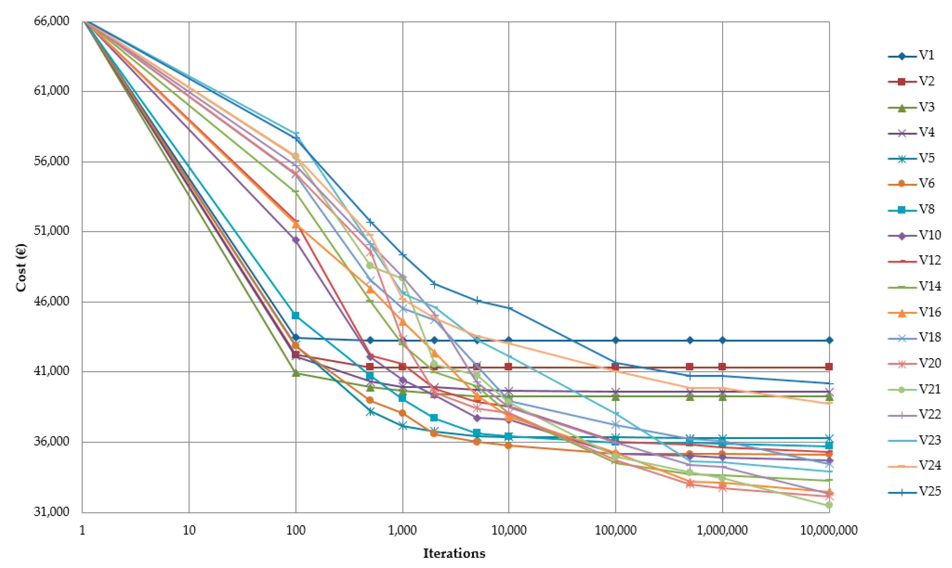
The movements set out in the study modified 1 to 25 variables. The number of iterations used with no improvement were 100, 500, 1000, 2000, 5000, 10,000, 100,000, 500,000, 1 million, and 10 million. Figure 3 shows the average cost values according to the number of iterations stop criteria. With movements of one, two, three, four, and five variables, the algorithm converged very quickly in such a way that improvements were no longer achieved from 500, 5,000, 100,000, and 500,000 iterations, respectively. Movements of more than five variables always improved the results, as the number of iterations increased, starting to converge from 10,000 iterations. The most balanced evolution was given to a movement of five or six variables; given that it converged from 10,000 iterations.

3.2. Hybrid Simulated Annealing with a Mutation Operator

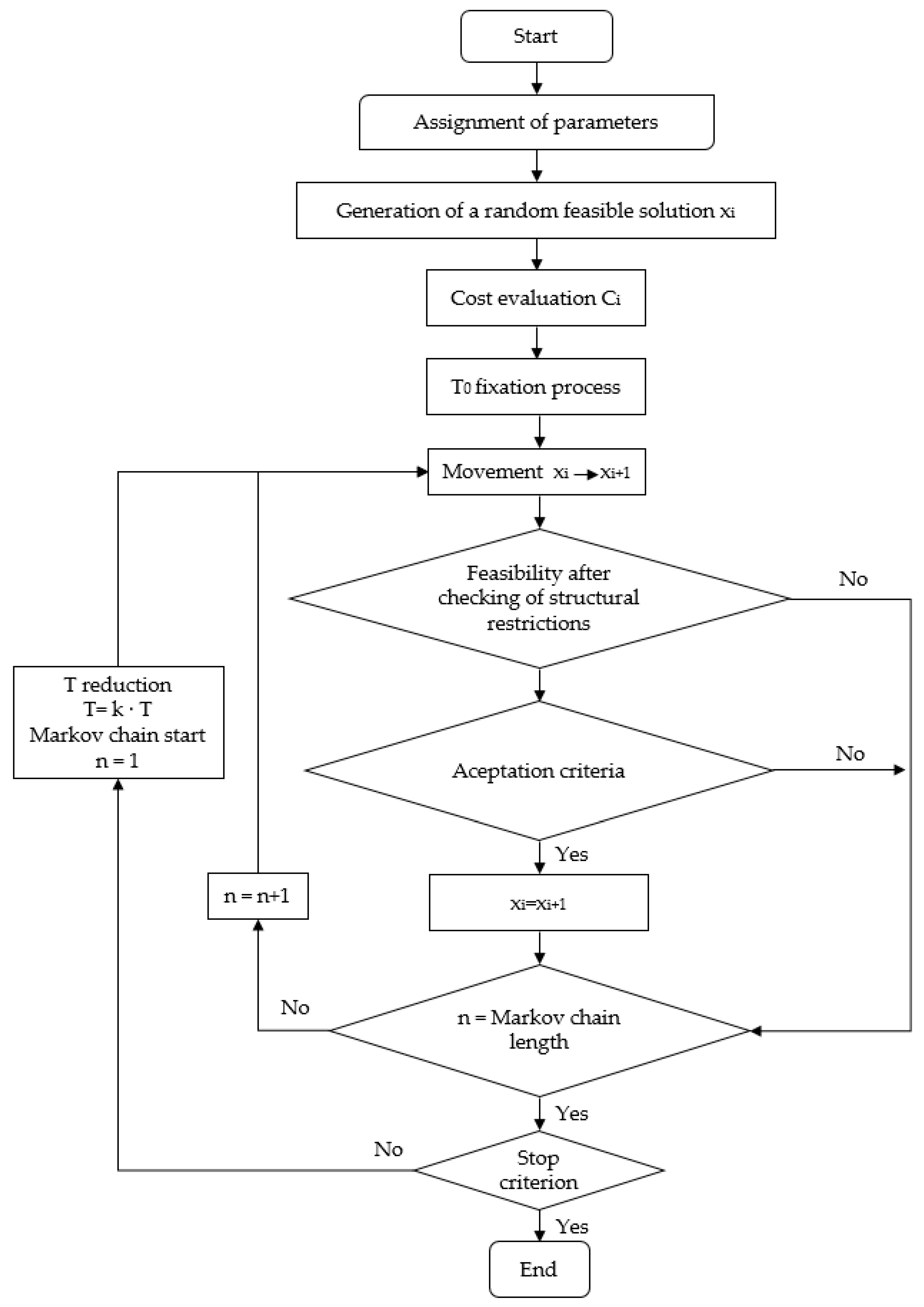
The hybrid simulated annealing (SA) with a mutation operator (SAMO2) is an algorithm developed by Martí et al. [26] (Figure 4). This technique is used to combine the advantages of good convergence of SA and the promotion of the diversity of the genetic strategy. SA, developed by Kirkpatrick et al. [46], is based on the analogy of the thermodynamic behavior of a set of atoms to form a crystal. “Annealing” is the chemical process of heating and cooling a material in a controlled fashion. Genetic algorithms seek the best solution through operators such as selection, crossover, and mutation. Soke and Bingul [32] effectively combined both algorithms. SAMO2 introduces the probabilistic acceptance of poorer quality solutions during the process, allowing it to escape from local optimums and to finally find the highest quality solutions. To do this, it accepts worse solutions with a probability Pa, given by the expression of Glauber (5), where T is now a parameter that decreases with the time, thus reducing the probability of accepting worse solutions, from an initial value, T0:
P a = 1 1 + e Δ E T .
This method was applied using the following fixed variable movements: 2, 3, 4, 5, 6, and 12. The initial temperature was set by the method proposed by Medina [47]. Markov chain lengths of 5,000, 10,000, 20,000, and 30,000 were tested. In this work, a geometrical cooling of the type T i + 1 = k · T i was adopted, considering k < 1, which has the advantage of prolonging the final phase of the search when the temperature is low. The coefficients k used were 0.80, 0.85, 0.90, and 0.95. For the stop criteria, two were set in this study: that the temperature was less than 0.001·T0 or that during a Markov chain no better solution was found.
From the application of the SAMO2 algorithm, graphs of trajectories of the cost, according to the number of iterations or the time, were obtained, as in Figure 5. This figure shows the trajectory of one of the rehearsed processes, where a correct operation of the algorithm is appreciated, initially accepting high worsening, which decreases as the process progresses, focusing the search on solutions with similar or lower costs, which divides the process into an initial diversification phase and a final intensification phase.

3.3. Glow-worm Swarm Optimization (GSO)

The glow-worm swarm optimization algorithm mimics the behavior of a firefly swarm and was proposed by Krishnanand and Ghose [48]. Glow-worms produce a natural light that is used as a signal to attract a partner. Each glow-worm carries an amount of luminescence, which we will call “luciferin”. It is considered that the maximum distance at which this luminescence is perceived is limited by a maximum radial value, which we will call the sensitivity radius rs. So, the decision range for each glow-worm is also delimited by a maximum radial value rid, that complies with 0 < ridrs, which we will call a decision radius. One glow-worm i considers another firefly j as its neighbor if j is within its decision radius rid and the level of luciferin j is greater than that of i.
The rid decision radius allows the selective interaction of neighbors and helps the disjointed formation of sub-branches. Each firefly selects, through a probabilistic mechanism, a neighbor, who has a higher value of luciferin and moves towards it. These movements, which are based solely on local information and the selective interaction of neighbors, allow the swarm of fireflies to be subdivided into disjointed subgroups, that address, and are found in multiple optimums of the given multimodal function. The process can be summarized as follows:
  • Initially a swarm of n feasible glow-worms is generated and distributed in the search space. Each glow-worm has assigned the initial luciferin value l0 and the initial sensitivity radius rs;
  • Depending on the previous luciferin li and the objective function value, the luciferin is updated as is shown on Equation (6). The luciferin value decays constant ρ   ( 0 < ρ < 1 ) simulates the decrease in luciferin level over time, and the luciferin enhancement constant γ (0 < γ < 1) is the proportion of the improvement in the objective that glow-worm adds to its luciferin. J(xi(t)) is the value of the objective function of the glow-worm i at iteration j:
    l i ( t ) = ( 1 ρ ) · l i ( t 1 ) + γ · J ( x i ( t ) ) ;
  • Each glow-worm uses a probability sampling mechanism to move towards a neighbor with a higher luciferin value. For each glow-worm i, the probability of moving to a neighbor j is given by Equation (7), where Ni(t) is the set of neighbors of the glow-worm i in the iteration t, dij represents the Euclidean distance between glow-worms i and j in iteration t. rid(t) is the decision ratio of glow-worm i in iteration j:
    p i j ( t ) = l j ( t ) l i ( t ) k N i ( t ) l k ( t ) l i ( t )   ;   j N i ( t )   ,     N i ( t ) = { j : d i j ( t ) < r d i ( t )   ;   l i ( t ) < l j ( t ) } ;
  • During the movement phase, the glow-worm i moves to glow-worm j. Equation (8) describes the model of the movement of a glow-worm at any given moment, where xi(t) is the location of the glow-worm i at iteration t and s is the step factor constant:
    x i ( t + 1 ) = x i ( t ) + s · ( x j ( t ) x i ( t ) x j ( t ) x i ( t ) ) ;
  • Once the movement is finished, the update of the radial sensor range is carried out by the expression of Equation (9), where β is a constant parameter and nt is another parameter that controls the number of neighbors:
    r d i ( t + 1 ) = m i n { r s , m a x { 0 ,   r d i ( t ) + β · ( n t | N i ( t ) | ) } } .
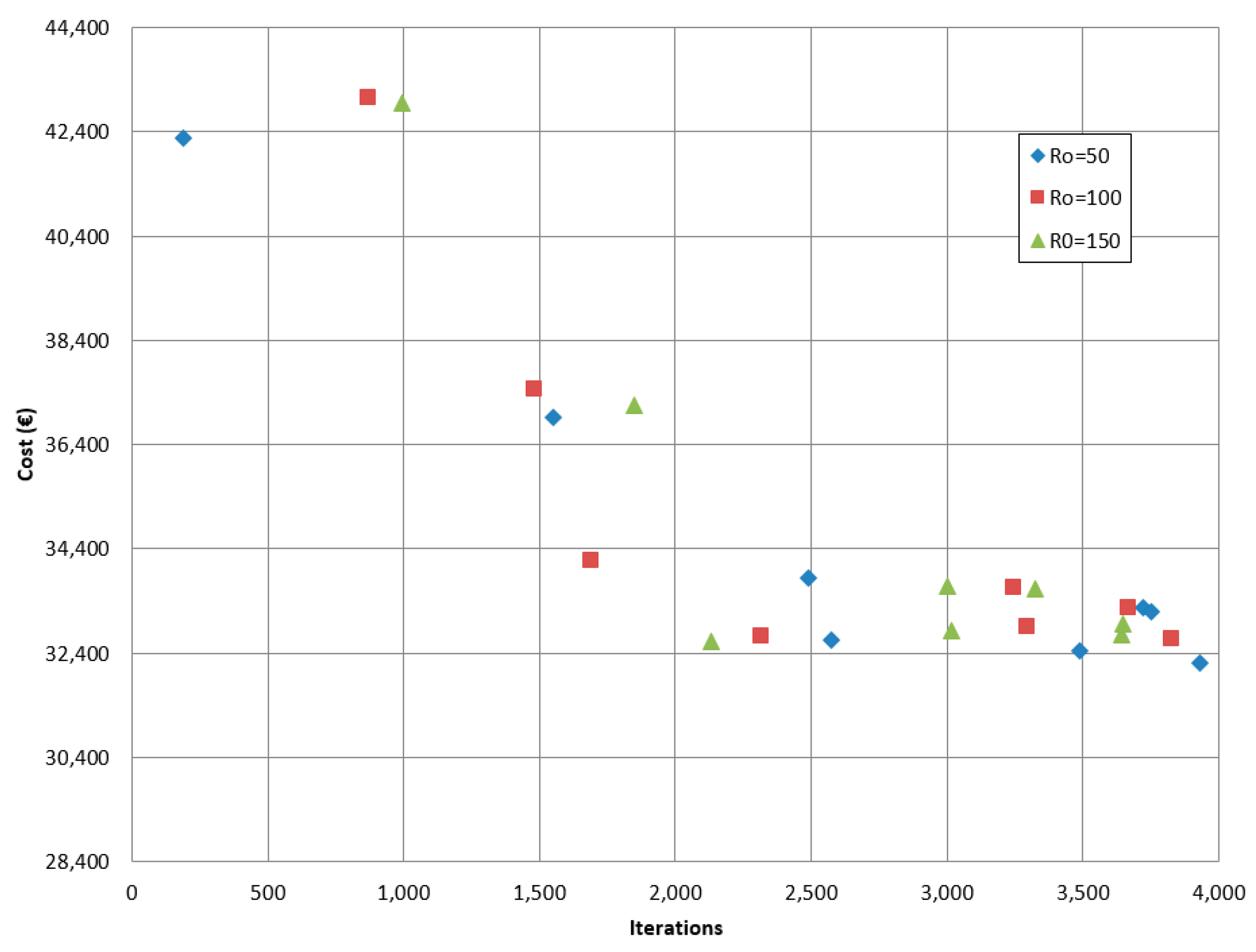
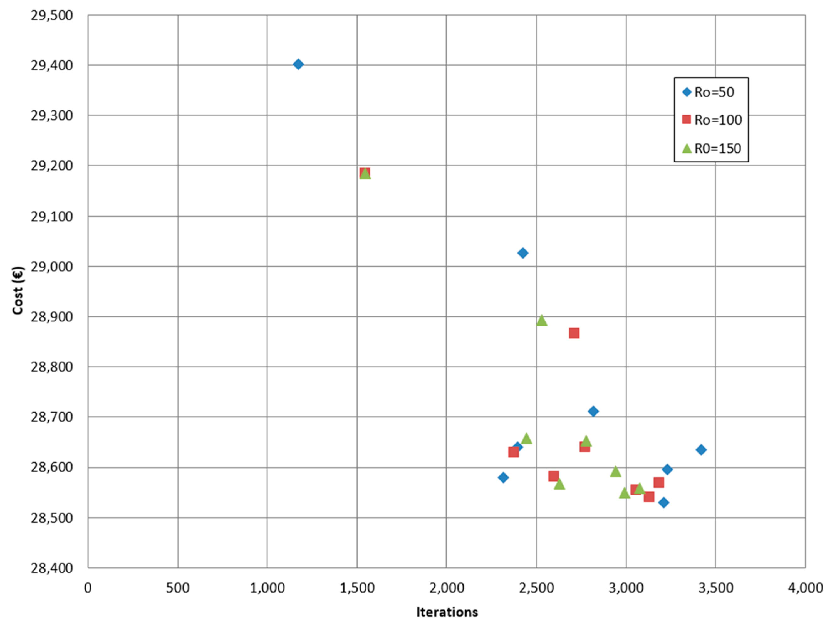
In this work, the GSO algorithm was applied to reach an optimum solution for a steel-concrete composite pedestrian bridge. The values of the parameters used to apply this method were 0.5, 0.1, 0.5, 2, 0.25, and 4 for   ρ   , γ, β, nt, s, and l0, respectively. The maximum number of iterations was fixed at 4000. The values of n and r0 were taken as different values; the values adopted in the study are shown in Table 4.
In this work, the GSO algorithm was applied in two experiments. The first one only used the GSO to reach the optimum solution, but in the second, the DLS algorithm was applied to the best solutions of the GSO to improve those solutions. Figure 6 and Figure 7 show the results of the GSO and GSO with DLS, respectively.

4. Discussion

4.1. Comparison of the Heuristic Techniques

To compare the results of the heuristic techniques, we focused on the cost obtained by each one. In Table 5, the results of material amounts and cost for each solution are shown. The heuristic that obtained the lowest cost is GSO combined with DLS. This result is related to the low amount of rolled steel achieved, due to the importance of this material in steel-concrete composite pedestrian bridges. As is seen in Table 5, the heuristics with lower values of cost (SA and GSO with DLS) have a lower amount of rolled steel.
The concrete strength was the same for DSL, SA, and GSO, but when GSO and DSL were combined, the geometry variables of the slab decreased due to the increase in the concrete strength, leveraging the material. The optimum solution for a steel beam consists of locating the area of steel in a way that allows the mobilization of the highest possible mechanical arm. In order to reach the lowest cost, the solutions obtained by the optimization algorithms looked for greater depths with lower amounts of material, increasing the inertia and reducing the structure weight.

4.2. Sustainability Study

An analysis of the CO2 emissions associated with the amount of the materials obtained from every cost heuristic optimization was carried out. In addition, a comparison with the original project of this steel-concrete composite pedestrian bridge was performed. In Table 6, the values of cost and CO2 emissions of every solution are compared.
As is seen in this table, the GSO and DLS combination heuristic obtained a reduction of 8.12% of the CO2 emissions compared with the reference. This means that an improvement of 1 €/m2 produced a reduction of the 1.74 kg CO2/m2.

4.3. Parametric Study

A parametric study for varying span lengths is presented with the GSO and DLS combination optimization model. Five span lengths were considered: 28, 32, 38, 42 and 48 m. The characteristics that were studied are the economy, the geometry, and the amount of materials. Table 7 and Table 8 compile the values of the features of the optimization solutions: Table 7 gives the main values of the geometry of the structure, and Table 8 gives the values of the measurements of the amount of materials of the structure.
The results of the parametric study led to practical rules for the preliminary design of cost-optimized steel-concrete composite pedestrian bridges with box-girder cross sections isostatic spans. The discussion of the results was carried out together, with a regression analysis. The functions obtained were valid approximations within the range of the studied parameters. The extrapolation of these results to other span lengths should be carried out carefully.
Figure 8 shows the average results of the cost of the structure per square meter of the steel-concrete composite pedestrian bridge for distinct span lengths. The cost evolution as a function of the horizontal span leads to a very good quadratic correlation. The average footbridge cost adjusted to C = 0.1954L2 − 8.0873L + 325.96 with a regression coefficient of R2 = 0.9994. The cost rising is produced by the need for larger amounts of materials to satisfy the deflection requirements. Note that the R2 regression coefficient in Figure 8 is almost 1, this indicates a very good correlation. The variations between the minimum and the mean cost of the pedestrian bridge produced by the GSO and DLS combination are 0.42%.
Figure 9 shows the mean values of the depth of the steel beam (CA) for different span lengths. The depth of the beam has a good linear variation, according to the span length of the bridge. The average depth of the beam adjusts to CA = 0.0369L − 0.2179 with R2 = 0.9927. Again, the good correlation factor represents a functional relationship.
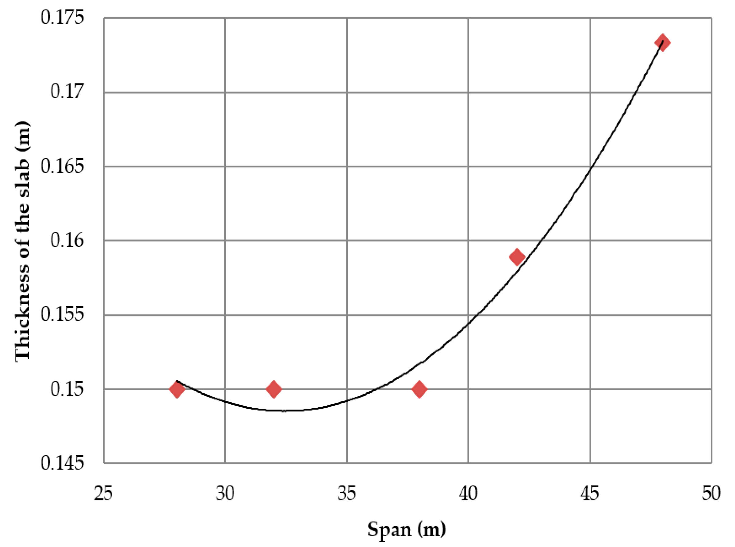
As shown in Figure 10, a function was found relating the thickness of the slab with different span lengths. Up to a certain span length, the slope of the parabola is smaller because the inertia of the slab is determined by the transverse flexion. Once the slab stresses are determined by the longitudinal deflection, the slope of the curve increases. The average slab thickness adjusts to CL = 0.0001L 2 − 0.0067L + 0.2568 with R2 = 0.9849 when the span length is larger than 38 m. Related to the compressive strength of the concrete of the slab, Figure 11 shows the relationship of the concrete compressive characteristic strength and the span length. This relationship adjusts well to a quadratic function. The concrete compressive strength adjusts to FCK = 0.0292L2 − 1.6959L + 49.714 with R2 = 0.9987. Note that the highest concrete compressive strength considered for this study was 35 MPa.
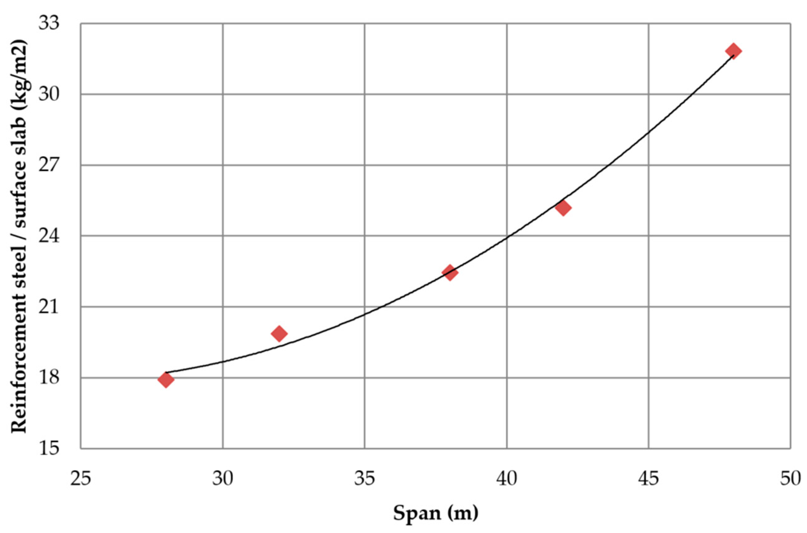
Regarding the ratio of the amount of rolled steel (Rs) and the surface of the slab (Ss) Figure 12 illustrates the increase in the amount of rolled steel needed to resist the flexural requirements. The slope of the curve tends to increase as the span length increases. The mean amount of rolled steel in relation to the surface of slab adjusts to Rs/Ss = 0.01913L2 − 3.5553L + 154.96 with R2 = 0.9996. However, the ratio of the volume of concrete (Vc) and the surface slab fits a second order equation that increases with the span length in the same way as rolled steel amount, as seen in Figure 13. The mean ratio of the volume of concrete in relation to the surface of slab adjusts to Vc/Ss = 0.0001L2 − 0.0067L + 0.245. Moreover, the ratio of reinforcing steel (RFs) measured per square meter of slab shows the same tendency as rolled steel amount and concrete volume. The ratio of reinforced steel in relation to the surface of slab adjusts to RFs/Ss = 0.0246L 2 − 1.2009L + 32.516 with R2 = 0.9955, as shown in Figure 14.

5. Conclusions

Three heuristic algorithms were applied to a steel-concrete composite pedestrian bridge to find an efficient design. DLS, SA, and GSO are used to automatically find optimum solutions. All procedures are useful in the automated design of steel-concrete composite pedestrian bridges. Furthermore, a parametric study was carried out. The conclusions are as follows:
  • The GSO optimization algorithm obtained worse results than DLS and SA, but if we apply the DLS to the best GSO solutions, then this combination of heuristic techniques reaches the lowest cost solution;
  • The results show the potential of the application of heuristic techniques to reach automatic designs of composite pedestrian bridges. The reduction in costs exceeds 20%. It is important to note that the current approach eliminates the need for experience-based design rules;
  • The CO2 emission comparison showed that the reduction between the original structure and the GSO with DLS combination optimized structure reduced the CO2 emission by 21.21%. Thus, an improvement of 1 €/m2 produced a reduction of 1.74 kg CO2/m2. Therefore, the solutions that are acceptable in terms of CO2 emissions are also viable in terms of cost, and vice versa;
  • The results indicate that cost optimization is a good approach to environmentally friendly design, as long as cost and CO2 emission criteria reduce material consumption;
  • The parametric study showed that there is a good correlation between span length and cost, amount of material, and geometry. This relationship could be useful for designers, to have a guide to the day-to-day design of steel-concrete composite pedestrian bridges. However, the tendencies of the thickness of the flanges and webs of the steel beam are not clear;
  • The heuristic techniques look for lower amounts of materials, which allows the reduction of the self-weight of the structure. In addition, the optimization algorithms look for an increase of the depth of the section to improve their mechanical characteristics. For an optimized pedestrian bridge, the relationship between the steel beam depth and span length takes a value of 1/27.

Author Contributions

This paper represents a result of teamwork. The authors jointly designed the research. D.M.-M. drafted the manuscript. V.Y., M.D.-G., J.V.M., and V.J.L.-D. edited and improved the manuscript until all authors are satisfied with the final version.

Acknowledgments

The authors acknowledge the financial support of the Spanish Ministry of Economy and Business, along with FEDER funding (DIMALIFE Project: BIA2017-85098-R).

Conflicts of Interest

The authors declare no conflict of interest.

References

  1. Liu, S.; Tao, R.; Tam, C.M. Optimizing cost and CO2 emission for construction projects using particle swarm optimization. Habitat Int. 2013, 37, 155–162. [Google Scholar] [CrossRef]
  2. World Commission on Environment and Development. Our Common Future; Oxford University Press: Oxford, UK, 1987. [Google Scholar]
  3. Ministerio de Fomento. Instrucción Sobre las Acciones a Considerar en el Proyecto de Puentes de Carretera (IAP-11); Ministerio de Fomento: Madrid, Spain, 2011.
  4. Ministerio de Fomento. Instrucción de Hormigón Estructural (EHE-08); Ministerio de Fomento: Madrid, Spain, 2008.
  5. Ministerio de Fomento. Instrucción de Acero Estructural (EAE-11); Ministerio de Fomento: Madrid, Spain, 2011.
  6. Ministerio de Fomento. Recomendaciones Para el Proyecto de Puentes Mixtos de Carretera (RPX-95); Ministerio de Fomento: Madrid, Spain, 1995.
  7. European Committee for Standardization. Eurocode 1: Actions on Structures-Part 1-4: General Actions-Wind Actions; European Committee for Standardization: Brussels, Belgium, 2005. [Google Scholar]
  8. European Committee for Standardlzation. BS EN 1992-2: 2005—Eurocode 2: Design of Concrete Structures—Part 2: Concrete Bridges—Design and Detailing Rules; European Committee for Standardization: Brussels, Belgium, 2005. [Google Scholar]
  9. European Committee for Standardization. CEN/TC250 EN1993: Eurocode 3 Design of Steel Structures—Part 2: Steel Bridges; European Committee for Standardization: Brussels, Belgium, 2006. [Google Scholar]
  10. Aashto. AASHTO LRFD Bridge Design Specifications; American Association of State Highway and Transportation Officials: Washington, DC, USA, 2012. [Google Scholar]
  11. Ministerio de Fomento. New Overpasses: General Concepts; Ministerio de Fomento: Madrid, Spain, 2000.
  12. Li, L.J.; Huang, Z.B.; Liu, F. A heuristic particle swarm optimization method for truss structures with discrete variables. Comput. Struct. 2009, 87, 435–443. [Google Scholar] [CrossRef]
  13. Martí, J.V.; Yepes, V.; González-Vidosa, F. Memetic algorithm approach to designing precast-prestressed concrete road bridges with steel fiber reinforcement. J. Struct. Eng. 2015, 141, 04014114. [Google Scholar] [CrossRef]
  14. Goldberg, D.E.; Samtani, M.P. Engineering Optimization via Genetic Algorithm; ASCE: Leston, VA, USA, 1991. [Google Scholar]
  15. Cohn, M.Z.; Dinovitzer, A.S. Application of Structural Optimization. J. Struct. Eng. 1994, 120, 617–650. [Google Scholar] [CrossRef]
  16. Sarma, K.C.; Adeli, H. Cost optimization of steel structures. Eng. Optim. 2000, 32, 777–802. [Google Scholar] [CrossRef]
  17. Sarma, K.C.; Adeli, H. Cost optimization of concrete structures. J. Struct. Eng. 1998, 124, 570–578. [Google Scholar] [CrossRef]
  18. Torres-Machi, C.; Yepes, V.; Alcalá, J.; Pellicer, E. Optimization of high-performance concrete structures by variable neighborhood search. Int. J. Civ. Eng. 2013, 11, 90–99. [Google Scholar]
  19. Adeli, H.; Kim, H. Cost optimization of composite floors using neural dynamics model. Commun. Numer. Methods Eng. 2001, 17, 771–787. [Google Scholar] [CrossRef]
  20. Kravanja, S.; Šilih, S. Optimization based comparison between composite I beams and composite trusses. J. Constr. Steel Res. 2003, 59, 609–625. [Google Scholar] [CrossRef]
  21. Senouci, A.; Alansari, M. Cost Optimization of Composite Beams Using Genetic Algorithms. Adv. Eng. Softw. 2009, 40, 1112–1118. [Google Scholar] [CrossRef]
  22. Kaveh, A.; Abadi, A.S.M. Cost optimization of a composite floor system using an improved harmony search algorithm. J. Constr. Steel Res. 2010, 66, 664–669. [Google Scholar] [CrossRef]
  23. Ramires, F.B.; De Andrade, S.A.L.; Da Silva Vellasco, P.C.G.; De Lima, L.R.O. Genetic algorithm optimization of composite and steel endplate semi-rigid joints. Eng. Struct. 2012, 45, 177–191. [Google Scholar] [CrossRef]
  24. Kaveh, A.; Behnam, A.F. Cost optimization of a composite floor system, one-way waffle slab, and concrete slab formwork using a charged system search algorithm. Sci. Iran. 2012, 19, 410–416. [Google Scholar] [CrossRef] [Green Version]
  25. Yepes, V.; Alcala, J.; Perea, C.; González-Vidosa, F. A parametric study of optimum earth-retaining walls by simulated annealing. Eng. Struct. 2008, 30, 821–830. [Google Scholar] [CrossRef]
  26. Martí, J.V.; Gonzalez-Vidosa, F.; Yepes, V.; Alcalá, J. Design of prestressed concrete precast road bridges with hybrid simulated annealing. Eng. Struct. 2013, 48, 342–352. [Google Scholar] [CrossRef] [Green Version]
  27. García-Segura, T.; Yepes, V. Multiobjective optimization of post-tensioned concrete box-girder road bridges considering cost, CO2 emissions, and safety. Eng. Struct. 2016, 125, 325–336. [Google Scholar] [CrossRef]
  28. Yepes, V.; Martí, J.V.; García-Segura, T.; González-Vidosa, F. Heuristics in optimal detailed design of precast road bridges. Arch. Civ. Mech. Eng. 2017, 17, 738–749. [Google Scholar] [CrossRef]
  29. García-Segura, T.; Yepes, V.; Frangopol, D.M. Multi-objective design of post-tensioned concrete road bridges using artificial neural networks. Struct. Multidiscip. Optim. 2017, 56, 139–150. [Google Scholar] [CrossRef]
  30. García-Segura, T.; Yepes, V.; Alcalá, J.; Pérez-López, E. Hybrid harmony search for sustainable design of post-tensioned concrete box-girder pedestrian bridges. Eng. Struct. 2015, 92, 112–122. [Google Scholar] [CrossRef]
  31. Li, X.G.; Wei, X. An improved genetic algorithm-simulated annealing hybrid algorithm for the optimization of multiple reservoirs. Water Resour. Manag. 2008, 22, 1031–1049. [Google Scholar] [CrossRef]
  32. Soke, A.; Bingul, Z. Hybrid genetic algorithm and simulated annealing for two-dimensional non-guillotine rectangular packing problems. Eng. Appl. Artif. Intell. 2006, 19, 557–567. [Google Scholar] [CrossRef]
  33. Penadés-Plà, V.; García-Segura, T.; Yepes, V. Accelerated optimization method for low-embodied energy concrete box- girder bridge design. Eng. Struct. 2019, 179, 556–565. [Google Scholar] [CrossRef]
  34. Yepes, V.; García-Segura, T.; Moreno-Jiménez, J.M. A cognitive approach for the multi-objective optimization of RC structural problems. Arch. Civ. Mech. Eng. 2015, 15, 1024–1036. [Google Scholar] [CrossRef]
  35. Martí, J.V.; García-Segura, T.; Yepes, V. Structural design of precast-prestressed concrete U-beam road bridges based on embodied energy. J. Clean. Prod. 2016, 120, 231–240. [Google Scholar] [CrossRef]
  36. García-Segura, T.; Yepes, V.; Frangopol, D.M.; Yang, D.Y. Lifetime reliability-based optimization of post-tensioned box-girder bridges. Eng. Struct. 2017, 145, 381–391. [Google Scholar] [CrossRef]
  37. Penadés-Plà, V.; García-Segura, T.; Martí, J.V.; Yepes, V. A review of multi-criteria decision-making methods applied to the sustainable bridge design. Sustainability 2016, 8, 1295. [Google Scholar] [CrossRef]
  38. Goedkoop, M.; Spriensma, R. The Eco-Indicator 99: A Damage Oriented Method for Life Cycle Impact Assessment; Prazska Energetika, A.S.: Prague, Czech Republic, 2001. [Google Scholar]
  39. Alcorn, A. Embodied Energy and CO2 Coefficients for NZ Building Materials; Centre for Building Performance Research: Dallas, TX, USA, 2003. [Google Scholar]
  40. Catalonia Institute of Construction Technology. BEDEC ITEC Materials Database. Available online: https://metabase.itec.cat/vide/es/bedec (accessed on 16 May 2019).
  41. Yepes, V.; Martí, J.V.; García-Segura, T. Cost and CO2 emission optimization of precast-prestressed concrete U-beam road bridges by a hybrid glowworm swarm algorithm. Autom. Constr. 2015, 49, 123–134. [Google Scholar] [CrossRef]
  42. Molina-Moreno, F.; Martí, J.V.; Yepes, V. Carbon embodied optimization for buttressed earth-retaining walls: Implications for low-carbon conceptual designs. J. Clean. Prod. 2017, 164, 872–884. [Google Scholar] [CrossRef]
  43. Martínez-Calzón, J.; Ortiz-Herrera, J. Construcción Mixta Hormigón-Acero; Editorial Rueda: Alcon, Spain, 1978. [Google Scholar]
  44. Viñuela-Rueda, L.; Martínez-Salcedo, J. Proyecto y Construcción de Puentes Metálicos y Mixtos; APTA: Washington, DC, USA, 2009. [Google Scholar]
  45. ACHE. Grupo de Trabajo 5/3 Puentes Mixtos Monografía M-10; ACHE: Chicago, IL, USA, 2016. [Google Scholar]
  46. Kirkpatrick, S.; Gelatt, C.D.; Vecchi, M.P. Optimization by simulated annealing. Science 1983, 220, 671–680. [Google Scholar] [CrossRef]
  47. Medina, J.R. Estimation of Incident and Reflected Waves Using Simulated Annealing. J. Waterw. Port Coast. Ocean Eng. 2001, 127, 213–221. [Google Scholar] [CrossRef]
  48. Krishnanand, K.N.; Ghose, D. Glowworm swarm optimisation: A new method for optimising multi-modal functions. Int. J. Comput. Intell. Stud. 2009, 1, 93–119. [Google Scholar] [CrossRef]
Figure 1. Box-girder geometrical variables and reinforcement.
Applsci 09 03253 g001
Figure 2. Flowchart of the descent local search (DLS) process.
Applsci 09 03253 g002
Figure 3. Average costs and number of iterations stop criteria.
Applsci 09 03253 g003
Figure 4. Flowchart of the hybrid simulated annealing with a mutation operator (SAMO2) process.
Applsci 09 03253 g004
Figure 5. Trajectory cost and temperature-iterations.
Applsci 09 03253 g005
Figure 6. Average cost to average iterations for the glow-worms swarm optimization (GSO) experiment.
Applsci 09 03253 g006
Figure 7. Average cost to average iterations for GSO and DLS combination experiment.
Applsci 09 03253 g007
Figure 8. Average cost for different span lengths.
Applsci 09 03253 g008
Figure 9. Mean steel beam depth for different span lengths.
Applsci 09 03253 g009
Figure 10. Mean slab thickness for different span lengths.
Applsci 09 03253 g010
Figure 11. Average compressive strength for different span lengths.
Applsci 09 03253 g011
Figure 12. Variation in the ratio of the rolled steel amount in relation to the surface of the slab with the span.
Applsci 09 03253 g012
Figure 13. Variation in the ratio of the volume of concrete in relation to the surface of the slab with the span.
Applsci 09 03253 g013
Figure 14. Variation in the ratio of the reinforcement steel in relation to the surface of the slab with the span.
Applsci 09 03253 g014
Table 1. Prices and CO2 emissions.
Unit MeasurementsCost (€)Emissions (kg CO2)
m3 of concrete C25/3093.71224.34
m3 of concrete C30/37102.41224.94
m3 of concrete C35/45105.56265.28
m3 of concrete C40/50111.64265.28
kg of steel (B-500-S)1.203.02
kg of shear-connector steel2.043.63
kg rolled steel (S-355-W)1.702.8
Concrete classification according to EN 1992
Table 2. Parameters considered in the analysis.
Geometrical Parameters
Pedestrian bridge widthB = 2.5 m
Number of spans1
Span length38 m
Material Parameters
Maximum aggregate size20 mm
Reinforcing steelB-500-S
Loading Parameters
Reinforced concrete specific weight25 kN/m3
Auxiliary assembly triangulations self-weight0.14 kN/m2
Live Load5 kN/m2
Dead load1.15 kN/m2
Temperature variation between steel and concrete±18 °C
Exposure Related Parameters
External ambient conditionsIIb
Code Related Parameters
Code regulationsEHE-08/IAP-11/RPX-95
Service working life100 years
Table 3. Box-girder geometrical variables description and values range.
Concrete Slab VariablesRange ValuesStep Size
CLSlab depth15 to 30 cm1 cm
CBSlab edge depth10 to 30 cm1 cm
VLLateral slab cantilever0.5 to 0.625 m5 mm
DTTransversal reinforcement diameter6, 8, 10, 12, and 16 mm-
DLSTop longitudinal reinforcement diameter6, 8, 10, 12, and 16 mm-
DLIBottom longitudinal reinforcement diameter6, 8, 10, 12, 16, 20, and 32 mm-
SBTCTransversal reinforcement separation in span center10 to 30 cm1 cm
SBTATransversal reinforcement separation in supports5 to 25 cm1 cm
NLSNumber of top longitudinal reinforcement bars10 to 401
NLINumber of bottom longitudinal reinforcement bars10 to 401
Metal Beam Variables
CAMetal beam depth1.086 to 2.375 m1 cm
AAIBottom flange width1 to 1.5 m1 cm
SRLLongitudinal stiffener spacing0, 0.16, 0.26, 0.36, and 0.46-
SRTTransversal stiffener spacing1, 2, 3.8, 7.6, 38 m-
EASTop flange thickness8 to 40 mm2 mm
EALWeb thickness8 to 40 mm2 mm
EAIBottom flange thickness8 to 40 mm2 mm
ERLLongitudinal stiffener thickness8 to 40 mm2 mm
ERTTransversal stiffener thickness8 to 40 mm2 mm
DPShear-connectors diameter16, 19, and 22 mm-
LPShear-connectors length100, 150, 175, and 200-
STPTransversal shear-connectors spacing5 to 25 cm5 cm
SLPCLongitudinal shear-connectors spacing in mid span30 to 50 cm5 cm
SLPATransversal shear-connectors spacing in supports10 to 30 cm5 cm
Mechanical Variables
FCKConcrete characteristic strength20 to 35 MPa5 MPa
Table 4. n and r0 adopted values.
n10203040506080100
r050100150
Table 5. Cost and material amount for the best heuristic solutions.
DLSSAGSOGSO and DLS
Rolled steelkg/m2153.99151.26157.49150.66
% Rolled/record%2.21%0.40%4.54%0.00%
Shear-connector steelkg/m20.900.900.790.90
% Shear-connector/record%14.28%14.28%0.00%14.28%
Concretem3/m20.150.150.140.14
% Concrete/record%7.52%7.52%0.83%0.00%
Reinforcement steelkg/m222.5722.2225.5022.23
% Reinforcement/record%1.58%0.00%14.76%0.04%
Cost€/m2304.82299.77313.18297.76
% Cost/record%2.37%0.67%5.18%0.00%
The rows with percentages express the increase in the quantity of material with respect to the minimum.
Table 6. CO2 emissions and cost data comparison from the reference solution and the heuristics.
ReferenceDLSSAGSOGSO and DLS
Cost€/m2399.10304.82299.77313.18297.76
% Cost/reference%-−23.62%−24.89%−21.53%−25.39%
CO2 emissionskg CO2/m2700.22536.39527.70552.54523.68
% Emissions/reference%-−23.40%−24.64%−21.09%−25.21%
Table 7. GSO with DLS combination for 28, 32, 38, 42, and 48 m spans.
Span (m)CL (m)CA (m)CT (m)EAS (mm)EAL (mm)EAI (mm)FCK (MPa)Total Depth/L
280.171.531.7018812350.035
320.161.371.5318810300.036
380.151.211.3618810300.036
420.150.961.1118810250.035
480.150.800.9518810250.034
Table 8. GSO with DLS combination measurements of the materials for 28, 32, 38, 42, and 48 m spans.
Span (m)Beam Rolled Steel (kg/m2)Slab Concrete (m3/m2)Slab Reinforcement (kg/m2)
28194.100.1730.87
32165.640.1524.63
38150.660.1422.23
42135.370.1419.80
48126.560.1417.84