Abstract
This work addresses the analysis of the influence of process parameters in laser piercing for mild steel, stainless steel, and aluminum thick sheets, carried out by the monitorization of the signal with a photodiode installed coaxially in the cutting head. The sensor captures the infrared or visible signal emitted during the piercing. The relationship between the intensity of the signal and the parameter values was analyzed, distinguishing between soft and fast piercings. The results permit the optimization of the piercing strategy with a reduction of 25% in time and the possibility of establishing a threshold to control the piercing process. This study reveals the importance of knowing parameter dependencies with the process results and highlights the potential of monitorization systems in laser cutting to improve the piercing duration and avoid wasting time during production.
1. Introduction
Piercing and laser cutting are two independent processes in which material evacuation have different mechanisms [1,2]. In the piercing, the laser beam is stationary with respect to the workpiece and the melt material is ejected upwards. In contrast, in the cutting process, the workpiece and the laser beam move with respect to each other and the material goes downwards. In laser cutting researchers focus on [3,4,5,6,7] dynamic phenomena and quality detection during the laser cutting progress. They presented that the main reason for adherent material was related to melt ejection on the walls of the kerf, showing that the optimal cutting speed for defect-free and low bottom roughness related to the striation formation in the sidewalls of the kerf could be determined. Less work was reported in cut interruptions or quality detection by photodiodes or visual monitoring. Authors developed algorithms based on single or dual photodiodes for laser cutting monitoring, detecting successfully cut interruptions in cuts of stainless steel, mild steel, and aluminum [8,9,10].
Regarding piercing processes, Rao et al. [11] worked on analyzing the influence of the parameters on the piercing appearance. The authors developed a new piercing technique known as PRPM (power ramped pulsed mode) obtaining smaller piercing holes with greater circularity and less ejected material than in normal pulse mode. In mild steel, researchers [2,11] observed that increasing the power of the peak or the duty cycle, increased the size of the hole and the irregularity of its shape and ejected material, also obtaining wider piercings with oxygen assist gas than with nitrogen. Pocorni et al. [12] investigated the piercing process in the laser cutting of stainless steel, demonstrating that appropriate laser power modulation settings could considerably reduce both the piercing time and the required energy to generate the piercing hole, also affecting its size.
To monitor piercing processes, technical approaches based on camera-based sensors, optical sensors, and acoustic-based systems have been reported. Rao et al. [11] monitored the piercing duration using two photodiodes and an oscilloscope that captured the visible spectrum, determining that the signal was low during the beginning and increased slowly with time due to the increase in the power of the peak during the ramp. De Keuster et al. [13] performed an analysis of the piercing process using a photodiode or a microphone. They observed that the signal dropped to negligible values when the piercing was achieved. Using the photodiode, the obtained signal was less susceptible to unwanted contributions since it was located inside the head, avoiding sources of noise such as ambient light. The acoustic signal needed to be filtered and processed because it captured noise from the cutting process (i.e., gas flow, laser). Kek et al. [14], through an analysis of acoustic-emission signals, found a good agreement between the quality of a laser cut and the number of bursts after the termination of laser cutting. The present work is an experimental study based on the analysis of the influence of the process parameters in laser piercing with the aim of optimizing piercing duration. The used tool is a monitoring system provided with a photodiode capable of capturing visible and infrared spectrum. The monitored signal intensity is evaluated and related to changes in piercing process parameters for mild steel, stainless steel, and aluminum thick sheets. Actually, it is possible to find commercial devices to detect the end of the piercing [15,16,17] or to optimize it by adjusting only laser power [18,19,20], or scientific studies on piercing that are focused on investigating the relationship between process parameters and piercing appearance [2,11,12]. This work will contribute to creating know-how on the influence of process parameters in laser piercing, to improving their duration and the development of new piercing strategies thanks to the possibility of efficiently modifying the piercing parameters based on parameter dependencies.
2. Experimental Section
2.1. Laser Cutting System
In this study, the experiments were carried out using a 5000 W fiber laser (IPG Photonics, Oxford, MA, USA). The laser beam was carried by a 100 μm diameter optical fiber to the cutting head (Precitec ProCutter, Germany) in which a 125 mm focal lens was used, resulting in a diameter spot laser of 125 μm when focusing on the workpiece (Figure 1). The monitorization was made by a sensor system installed coaxially to the nozzle in the cutting head; specifically, a sandwich consisted of a Si-diode (400–1100 nm) and a InGaAs-diode (1000–1800 nm), registering visible or infrared spectrum. The photodiodes detected the molten melt and vapor plume generated by the piercing and converted it into an analog signal that was used to analyze the piercing procedure. Filters were installed in the laser cutting head to avoid the registration of the laser pointer and reflected laser irradiation signals. Data was acquired through the oscilloscope integrated into the Fagor CNC 8070 (Fagor Automation, Basque Country, Spain) installed in the laser cutting system. The sample rate was 500 Hz, limited by the CNC cycle duration. The assisting gases were nitrogen and oxygen, with a purity greater than 99.999%, flowing coaxially to the laser beam. Gas nozzles (Precitec, Germany) with a diameter of 2.5 and 3 mm were used.
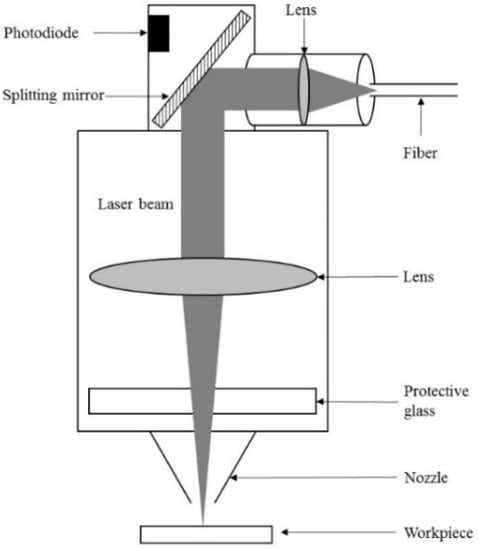
Figure 1.
Scheme of the experimental set-up.
2.2. Design of Experiments
The study was made with 20 mm thick sheets of mild steel (MS) and stainless steel (SS) and aluminum of 10 mm thick. The pressure, standoff, focal position, duties, and ramp time were varied to analyze their influence on the piercing process. Duties were used to reduce the energy, since they were related to the percentage that the laser pulse was turned on/off. By modifying duties and ramp time it was obtained frequency variation according to the selected percentages and time. Experiments were repeated at least three times to check stability. After finding the ideal parameters for the piercing process, to evaluate its functionality, a test pattern to be cut consisting on a rectangular piece of 25 × 30 mm2 with rounding corners (radius 4 mm) was chosen. The selection of infrared or visible signal in the monitorization for each material was based on previous laser cutting works, where each experiment was monitored with both signals. It was found that cuts with oxygen gas and nitrogen gas displayed better signals with visible and infrared spectra, respectively. In this paper, mild steel and aluminum are monitored with reference to the visible signal and stainless steel to the infrared signal. While infrared signal was related to temperature, the visible signal was explained as a consequence of vapor plume formation. Table 1 shows the ideal parameters for the three piercings. For MS, three consecutive piercings were needed to avoid explosions during the process.

Table 1.
Piercing parameters for mild steel 20 mm thick and stainless steel and aluminum 10 mm thick.
3. Results and Discussion
To analyze the results and based on the duration, the piercing process was divided into soft piercing and fast piercing, establishing the division in >1.5 s or less, respectively. Whereas in stainless steel and aluminum it was possible to develop a fast piercing, in mild steel, due to its thicker thickness (20 mm), a more gradual piercing process was required, taking longer than 1.5 s. In both cases, the signal intensity dropped drastically when piercing pierced the sheet, indicating the final stage of the process (when it is less than the programmed one) or the final stage of the programmed duration. It was observed that the programmed time was higher than the real needed time to pierce the sheet. Parameter influence determination done by the evaluation of signal monitorization optimized the piercing duration, requiring less time for the cutting process to continue. In the results, it was observed that a more intense signal did not imply that the piercing went through the metal sheet sooner. Soft piercing tests showed noisier signals due to lower frequency working values.
3.1. Soft Piercing
The influence of the programmed parameters in soft piercing processes of mild steel was studied, observing the visible signal intensity and, consequently, the vapor plume formation. It was observed that the signal value remained constant with the focal position and standoff variations (Figure 2; however, it varied for the rest of the parameters (Figure 3). Monitoring results showed that the vapor plume formation depended on parameters directly related to laser power, such as duties or ramp time, or on the material ejection produced by the gas. The selected pressure mainly affected the beginning of the process, which had a lower signal with less gas pressure due to less material evacuation and, finally, matching the signal value as the process continued and the vapor plume formation became steady. As the duties increased, the value of the monitored visible signal also increased, while from achieving a given value (20) the same signal intensity was always obtained. It was also observed that the ramp time of the first piercing affected the intensity of the signal. However, starting from a similar first piercing, the ramp time of the second piercing did not affect the intensity of the signal. The same explanation as for pressure could be applied for these last two studies, attributing the initial variation of signal intensity to the plume formation and, afterward, the obtaining of a fixed intensity value to its saturation. Figure 3b,c showed lower signal intensities for 8-14-18 duties percentages, and 1000-1000-1000 and 1000-500-1000 ramp times, respectively. In these cases, process conditions were softer and, thus, the plume remained constant without saturating.
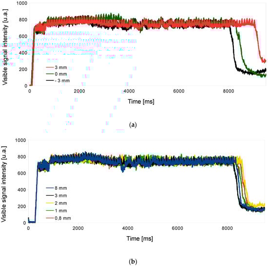
Figure 2.
Piercing monitored signal for mild steel 20 mm thick, varying (a) focal position; (b) standoff.
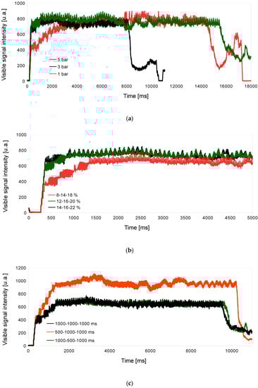
Figure 3.
Piercing monitored signal for mild steel 20 mm thick, varying (a) pressure; (b) duties percentage; (c) ramp time.
3.2. Fast Piercing
For stainless steel and aluminum thick sheets, a fast piercing process was required. The tests showed that the monitored signals did not have a clear relationship with the programmed values of the piercing parameter. However, in both samples ideal parameters displayed intensity signals in a determined range, making it possible to establish a threshold to control the piercing process.
In the case of stainless steel (Figure 4), the infrared monitored signal of ideal process conditions (black line) always gave off a lower intensity than the non-ideal ones. In this sense, and relating infrared signal and temperature, it could be explained that good piercing conditions generated lower intensity due to a lower temperature, thanks to having a minimum heating in the piercing zone.
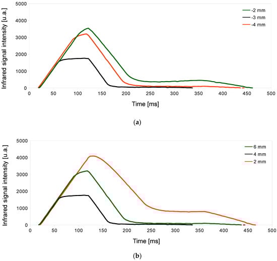
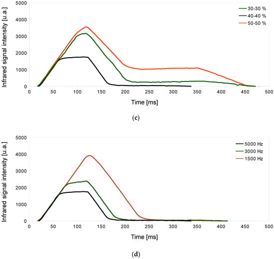
Figure 4.
Piercing monitored signal for stainless steel 10 mm thick, varying (a) focal position; (b) standoff; (c) duties percentage; (d) frequency. The ideal parameters are shown in black. Red and green parameters pierced the sheet with longer duration.
In aluminum piercing processes, the use of parameter values that involve an increase in laser power-provoked explosions, saturating the visible monitored signal (Figure 5) due to the vapor plume formation. The signal intensity displayed higher values than the ideal parameters when it was saturated as a consequence of the explosion of material.
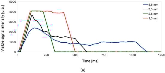
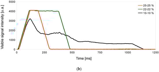
Figure 5.
Piercing monitored signal for aluminum 10 mm thick, varying (a) focal position; (b) duties percentage. Focal positions of 1.5 or 2.5 and duties percentages of 25 25 and 22 22 provoked explosions.
Table 2 resumes the monitored experiments and the displayed dependence with the process parameters.
Table 2.
Resume of monitored experiments and dependence of process parameters.
3.3. Optimization of Piercing Strategy
Based on the parameter dependencies observed during the monitoring of the piercing process, it was possible to optimize the strategy used in soft piercings. For mild steel 20 mm thick, firstly, a piercing programmed in three individual steps was used (Piercing A), each one with its own values of time, focal position, standoff, duties, and ramp time. The total piercing duration was 11–11.5 s. However, thanks to the information released from the monitoring, it was possible to select a single piercing (Piercing B) with continuous movement between two standoffs and with two combinations of duties and ramp time. This optimization was carried out through a design of experiments in which each process parameter was fixed and its monitoring signal analyzed in order to adjust each parameter for a better response in relation to time. Piercing A was based on the modification of the focal position maintaining the standoff. However, the know-how obtained in this study revealed that the piercing was affected by pressure, duties, and ramp time modifications. Thus, Piercing B was proposed taking into account these results. Pressure stabilization in laser cutting is not an immediate process, so this parameter was not directly modified. Piercing B duration showed a decrease when the focal position was fixed and the standoff was varied. This movement implied the approach of the cutting head to the sheet, improving the arrival of the gas to the piercing zone, and contributing to evacuate the material. Regarding duties and ramp time, the maximum values of duty minimum and duty maximum were selected without provoking explosion, and the ramp time was also minimized. Figure 6 shows that the final piercing duration was decreased to 8–8.6 s, obtaining a reduction in time of 25%. Table 3 summarizes piercing parameters values for each strategy.
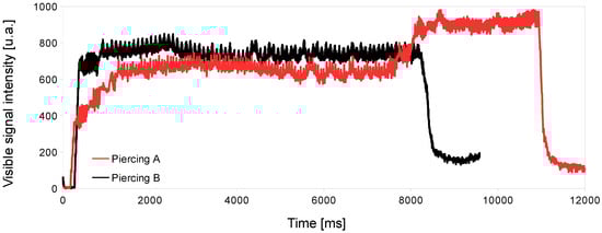
Figure 6.
Piercing monitored signal for mild steel 20 mm thick, varying piercing strategy.
Table 3.
Piercing parameters for mild steel 20 mm thick, for two different piercing strategies. Piercing A was programmed as three independent piercings and piercing B as a continuous descendent piercing process.
4. Conclusions
We reported on a study based on the analysis of the influence of the process parameters in laser piercing to create know-how in a field in which commercial devices detect the end of the piercing only improve piercing strategy based on laser power modifications, without considering other process parameters. A monitoring system provided with a sandwich of Si-diode (400–1000 nm) and InGaAs-diode (1000–1800 nm) that simultaneously captured the visible and infrared spectrum was used as a tool to evaluate and relate intensity signal changes to piercing process parameters for mild steel, stainless steel, and aluminum thick sheets. The selection of the monitored spectrum, visible or infrared, was done based on the gas used during the experiments, oxygen or nitrogen, respectively. The visible spectrum was associated with vapor plume detection and infrared spectrum with temperature. Soft piercing was required for mild steel 20 mm thick, observing visible monitored signal dependence with pressure, and duties percentage and ramp time, parameters directly related to the material ejection or to the formation of vapor plume by modifications in laser power, respectively. Based on these results, the piercing time duration was reduced by 25%. For stainless steel and aluminum 10 mm thick, fast piercing was used. In the first case, infrared signal intensity displayed a lower signal intensity in ideal piercing conditions than in non-ideal ones due to having a minimum heating in the piercing zone. Regarding aluminum, the visible signal was saturated when an explosion occurred, as a consequence of material ejection and vapor plume saturation. These results showed that the optimization of the piercing time for soft piercings was feasible thanks to the knowledge obtained from the monitoring inputs. For fast piercings exists also the possibility of establishing a threshold to control the piercing results. This paper shows the potential of the process monitorization, not only to detect the final stage of the piercing, but also to create knowledge that can optimize the actual piercing strategies.
Author Contributions
Conceptualization, S.M.G. and J.F.; methodology, S.M.G.; investigation, J.R. and S.M.G.; validation, J.R. and S.M.G.; formal analysis, S.M.G, A.L., and J.F.; resources, J.F.; writing—original draft preparation, S.M.G.; writing—review and editing, S.M.G, A.L., and J.F.
Funding
This research received no external funding.
Conflicts of Interest
The authors declare no conflict of interest.
References
- Poprawe, R. Modeling, monitoring and control in high quality laser cutting. CIRP Ann. 2001, 50, 137–140. [Google Scholar] [CrossRef]
- Hashemzadeh, M.; Powell, J.; Voisey, K.T. Fibre laser piercing of mild steel—The effects of power intensity, gas type and pressure. Opt. Lasers Eng. 2014, 55, 143–149. [Google Scholar] [CrossRef]
- Wen, P.; Zhang, Y.; Chen, W. Quality detection and control during laser cutting progress with coaxial visual monitoring. J. Laser Appl. 2012, 24, 032006. [Google Scholar] [CrossRef]
- Schuöcker, D.; Schuöcker, G. Dynamic phenomena and quality defects in laser cutting. In Proceedings of the International Symposium on High Power Laser Ablation 2012 AIP Conference, Santa Fe, NM, USA, 30 April–3 May 2012. [Google Scholar]
- Kaebernick, H.; Jeromin, A.; Mathew, P. Adaptive control for laser cutting using striation frequency analysis. Ann. CIRP 1998, 47, 137–140. [Google Scholar] [CrossRef]
- Sobih, M.; Crouse, P.L.; Li, L. Elimination of striation in laser cutting of mild steel. J. Phys. D Appl. Phys. 2007, 40, 6908–6916. [Google Scholar] [CrossRef]
- Wee, L.M.; Li, L. An analytical model for striation formation in laser cutting. Appl. Surf. Sci. 2005, 247, 277–284. [Google Scholar] [CrossRef]
- Schleier, M.; Adelmann, B.; Esen, C.; Hellmann, R. Cross-correlation based algorithm for monitoring laser cutting with high power fiber lasers. IEEE Sens. J. 2017, 18, 1585–1590. [Google Scholar] [CrossRef]
- Adelmann, B.; Schleier, M.; Neumeier, B.; Hellmann, R. Photodiode-based cutting interruption sensor for near-infrared lasers. Appl. Opt. 2016, 55, 1772–1778. [Google Scholar] [CrossRef] [PubMed]
- Adelmann, B.; Schleier, M.; Neumeier, B.; Wilmann, E.; Hellmann, R. Optical cutting interruption sensor for fiber lasers. Appl. Sci. 2015, 5, 544–554. [Google Scholar] [CrossRef]
- Rao, B.T.; Ittoop, M.O.; Kukreja, L.M. A power ramped pulsed mode laser piercing technique for improved CO2 laser profile cutting. Opt. Lasers Eng. 2009, 47, 1108–1116. [Google Scholar]
- Pocorni, J.; Powell, J.; Frostevarg, J.; Kaplan, A.F.H. Investigation of the piercing process in laser cutting of stainless steel. J. Laser Appl. 2017, 29, 022201. [Google Scholar] [CrossRef]
- De Keuster, J.; Duflou, J.R.; Kruth, J.P. Monitoring of high-power CO2 laser cutting by means of an acoustic microphone and photodiodes. Int. J. Adv. Manuf. Technol. 2017, 35, 115–126. [Google Scholar] [CrossRef]
- Kek, T.; Grum, J. Monitoring laser cut quality using acoustic emission. Int. J. Mach. Tool 2009, 49, 8–12. [Google Scholar] [CrossRef]
- Active Piercing. Available online: http://demo.blmgroup.com/en/innovation/innovative-solutions/activetools-fast-oxygen-piercing.aspx (accessed on 7 August 2019).
- Pierce Line. Available online: https://www.trumpf.com/filestorage/TRUMPF_Master/Products/Services/01_brochures/TRUMPF-product-enhancements-catalog-DE.pdf (accessed on 7 August 2019).
- Regulated Pulse Pierce (RPP). Available online: https://www.lmclaser.com.au/rpp-regulated-pulsed-piercing/ (accessed on 7 August 2019).
- Available online: https://www.balliu.be/products/laser-cutting/features/lpm-piercing-control/ (accessed on 7 August 2019).
- Available online: http://www.eckert-saga.com/en/maquinas/diamond-fiber-laser-2/#accessories (accessed on 7 August 2019).
- Available online: https://www.spilasers.com/wp-content/uploads/2017/11/Fiber-laser-piercing-enhances-cutting-productivity.pdf (accessed on 7 August 2019).
© 2019 by the authors. Licensee MDPI, Basel, Switzerland. This article is an open access article distributed under the terms and conditions of the Creative Commons Attribution (CC BY) license (http://creativecommons.org/licenses/by/4.0/).