Abstract
Asymmetric rotor systems widely exist in commercial plants. In the previous studies about asymmetric rotor systems, parameters such as material properties and boundary conditions are deterministic. To obtain a deep understanding of the dynamics of asymmetric rotor systems, a generator rotor system considering uncertain factors is studied in this paper. The equations of motion of the three-dimensional finite element model are solved in the rotating frame. The component mode synthesis is used to reduce the degrees of freedom. By employing the Chebyshev interval method (CIM), the uncertain gravity responses of the generator rotor system are investigated. The influences of the uncertainties in the bearing’s properties and the rotor’s material properties on the gravity response are studied in cases with a single uncertainty and double uncertainties. The accuracy and the efficiency of CIM are validated by comparing with the results of the scanning method. The results show that uncertainties have remarkable influences on the gravity response, and that these influences are different from each other. The proposed method and the results can provide guidance to the design and optimization of the rotary machinery.
1. Introduction
Research on the asymmetric rotor system is one branch of rotor dynamics. They widely exist in industrial plants, such as two-pole generator rotor [1] and cracked rotor [2,3]. The unequal principal second moments of area of the shaft section can make the dynamics of the asymmetric rotor systems different from the traditional rotor systems with circle shaft sections. In the previous studies focusing on the asymmetric rotor systems, the properties of the rotor system and the boundary condition are deterministic [4,5,6]. However, uncertainties are inevitable in reality, which can lead to uncertain dynamics. To gain a deep understanding of the asymmetric rotor system, uncertainties are considered in this paper.
In 1988, Leung and Fung [7] presented the matrix expressions of beam elements in the rotating frame, which promoted the development of the research on the asymmetric rotor system. Jei and Lee [8] established the finite element model in the rotating frame; their model considered the effects of rotary inertial, gyroscopic moment, transverse shear deformation, and internal damping. They used this model to analyze the whirl speed and forced vibration. Kang et al. [9] studied the dynamics of the asymmetric rotor system in the fixed frame. The matrix expressions of beam elements were presented in their study. The influences of the asymmetry of the disk and shaft on the forced responses were studied. Their study also considered the general asymmetric rotor systems. However, with the demand of capability for modeling large-scale asymmetric rotor systems without much simplification, the modeling techniques based on beam elements were gradually replaced by a three-dimensional finite element model (3D FEM). Rao and Sreenivas [10] modeled the asymmetric rotor by using 3D finite elements. The transient response due to unbalance alone and gravity alone were investigated. The gravity critical speed was reported in their study. Lazarus et al. [11] established the 3D FEM of the rotary part and stationary part in the rotating frame and fixed frame, respectively. The global equations of motion were obtained by coupling the two parts in a different frame. To accelerate the stability and steady-state analysis, component mode synthesis (CMS) was used to reduce the degrees of freedom (DOFs). Wang et al. [12] used a free-interface CMS to establish a reduced-order model (ROM). Thus, the DOFs of anisotropic rotor-bearing systems were reduced. The influences of four dimensionless parameters describing the anisotropy of bearing on the unbalance and gravity responses were analyzed and discussed. Ma et al. [13] experimentally and numerically studied the whirl speed of an asymmetric rotor system. In their numerical analysis, 3D FEM combined with model order reduction using modal shapes was employed. Then, their model order reduction technique was employed by Zuo et al. [14] to study the instability of the asymmetric rotor system with uncertainties. Zheng et al. [15] proposed a method that can reduce the interface DOFs when multiple substructures were used. This method was able to solve the steady-state response of large-scale asymmetric rotor systems.
The above studies indicated that valuable results concerning the stability and steady-state response of asymmetric rotors have been obtained by deterministic study, where the properties of rotor system and boundary conditions were deterministic. However, uncertainties were inevitable in reality, which could result in uncertain problems. The uncertain rotor system attracted the attention of researchers. The Monte Carlo method was one of the most straightforward methods to handle uncertain problems. Zuo et al. [14] employed the Monte Carlo method to study the bounds of the spin speed of unstable regions in an asymmetric rotor system. Although the Monte Carlo method was easy to carry out, the demand of large samples to obtain convergent results limits its developments. The polynomial chaos expansion (PCE) was a method that can overcome the demand of large samples. When using PCE, the uncertain response was replaced by polynomial chaos, of which the unknowns were the coefficients of the assumed polynomial. Didier et al. [16] proposed the stochastic finite element method based on PCE to analyze the uncertain response of a uncertain rotor system. The robustness and efficiency of the proposed method were validated by a comparison with the results of the Monte Carlo method. Didier et al. [17] extended the previous PCE for uncertain linear problems to uncertain nonlinear problems. The method they proposed was called the Stochastic Multi-dimensional Harmonic Balance Method. In their study, a two-DOF vibration problem with different types of nonlinearities was investigated to validate the proposed method. Then, their method was employed by Sinou et al. [18] to study the uncertain nonlinear vibration of a flexible rotor with nonlinearities due to cubic stiffness or clearance. Sinou and Jacquelin [19] studied the effect of the PCE order on the responses of an asymmetric rotor system with uncertainties. Results showed that the increase of PCE order could only reduce the level of spurious peaks, but could not eliminate them.
The above Monte Carlo method and PCE belong to the probabilistic method. Although the two methods were able to solve uncertain problems, the probability distribution functions of uncertain factors should be known or assumed in advance. However, the probability distribution functions were not easy to gain in reality. Therefore, the assumption in the probability distribution functions could lead to unexpected error. An interval method that could overcome the difficulty of knowing the probability distribution functions in advance was proposed. In this interval method, the uncertain factors are treated as interval variables with the lower bounds and upper bounds. Rao and Berke [20] studied the uncertain response of static problems by using this interval method. A truncation approach was proposed to limit the unexpected growth of interval response. The results showed that the truncation approach was effective and necessary. Qiu et al. [21,22] studied the uncertain static and dynamic structure problem based on this interval method. The widths of the bounds predicted by the interval method were found to be larger than those of probabilistic method. To deal with the unexpected overestimation of uncertain response, the Chebyshev interval method (CIM) was proposed by Wu et al. [17,23]. In CIM, the interval response was expanded based on a Chebyshev series in which the calculation was independent from the calculation of response, i.e., in a non-intrusive way. Fu et al. [24] studied the uncertain nonlinear response of a breathing cracked rotor system. A surrogate model based on Chebyshev polynomial expansion was used in their study. Then, Fu et al. [25] proposed an effective method based on a polynomial surrogate model to reduce the computational efforts. Wei et al. [26] used CIM to study an uncertain geared transmission system. The interval responses influenced by uncertainties were evaluated. Then, Wei et al. [27] evaluated the uncertain nonlinear response of a single-mesh gear system. Besides, CIM was used to study uncertain thermodynamics [28,29,30].
The above analysis showed that few papers about uncertain asymmetric rotor systems have been published. In this paper, the gravity responses of a two-pole generator rotor system with interval uncertainties are evaluated. The fixed-interface CMS is employed to reduce the number of DOFs. The equations of motion of the ROM are solved in the rotating frame. A collocation CIM without integral operation is proposed to analyze the uncertain gravity response. By comparing with the scanning method, the accuracy and effectiveness of the proposed method are validated. Finally, the bounds of gravity responses influenced by different types of uncertain factors are obtained.
2. Methodology
2.1. Physical Model and Equations of Motion
The schematic diagram of a generator rotor system is shown in Figure 1. To meet the demand of electricity generation, the generator rotor is slotted in the circumferential direction. As a result, the generator rotor loses its axial symmetry and is called a two-pole generator rotor. The two-pole generator rotor has two unequal principal second moments of area. The vertical stiffness of the rotor changes twice in every rotational period, which makes the gravity response change twice and leads to double frequency vibration, i.e., a gravity response.
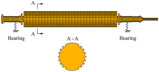
Figure 1.
The schematic diagram of a generator rotor system.
The generator rotor system is composed of a rotary part and a stationary part, i.e., a rotor and bearings. If the equations of motion of the generator rotor system are established in the fixed frame, the time-varying coefficients will occur in the equations of motion, which makes the equations difficult to solve. Considering that the time-varying coefficients are caused by the asymmetry of the generator rotor and the bearings in this paper are isotropic, the rotating frame is selected where the time-varying coefficients disappear. The aim of this paper is to study the gravity response of the generator rotor system with interval uncertainties. Thus, the only external excitation is gravity, and other external excitations such as unbalance forces are ignored.
In the rotating frame, the equations of motion of a 3D FEM of a generator rotor system excited by gravity can be expressed as:
where is the rotational speed; and are the mass and stiffness matrices of the generator rotor, respectively; is the Coriolis matrix; is the spin-softening matrix; and are the damping and stiffness matrices of bearings, respectively; and are the coefficient vectors of the cosine and sine functions of gravity vector, respectively; and is the displacement vector of the generator rotor system in the rotating frame.
The stiffness and damping matrices of bearing in the rotating frame are different from those in the fixed frame. If the bearing is anisotropic, the time-varying coefficients are inevitable in the rotating frame. However, the anisotropic bearing is out of the scope of this study, and the bearing discussed in this paper is isotropic. The cross-coefficients of isotropic bearing are equal to zero. The direct coefficients are identical. Therefore, in the rotating frame, the coefficients of the equations of motion of the generator rotor supported by isotropic bearing are time-independent.
The relationship between the physical variables in the rotating frame and in the fixed frame can be expressed as:
where and are the vectors of physical variables in the rotating frame and in the fixed frame, respectively, and is the transformation matrix.
The stiffness and damping matrices of bearing in the rotating frame can be transformed from those in the fixed frame. The supporting forces of bearing in the fixed frame can be expressed as:
where and are the direct coefficients of the stiffness and damping of the bearing, respectively; and are the horizontal and vertical supporting forces in the fixed frame; and and are the horizontal and vertical displacements of the bearing node in the fixed frame.
Considering the expressions in Equations (2) and (3), the damping and stiffness matrices of bearing in the rotating frame can be expressed as:
As shown in the above analysis, in the rotating frame, the stiffness coefficients of bearing are influenced by the damping coefficients, which are different from those in the fixed frame.
2.2. Deterministic Gravity Response Analysis Based on ROM
One of the drawbacks of 3D FEM is the enormous number of DOFs, which limit the application of the 3D FEM. The enormous number of DOFs will lead to large dimensional equations of motion that demand large computational efforts. Thus, to overcome the large computational efforts, the fixed-interface CMS [31] is employed in this paper to reduce the dimension of the equations of motion. During the reduction, the displacements of the generator rotor system are divided into interior displacements and boundary displacements . Consequently, the equations of motion before the reduction can be expressed as:
where:
The reduction by fixed-interface CMS is carried out by transforming the equations of motion in the physical space to the modal space. For the convenience of obtaining the gravity responses of the desired node, the physical coordinates of the desired node are treated as boundary DOFs that can be retained after the reduction. Thus, the physical coordinates of the generator rotor system by employing the fixed-CMS can be expressed as:
where is the retained normal modes matrix, which is composed of the first th real eigenvectors when fixing the boundary DOFs and ignoring the damping matrix in Equation (6); and is the constrained modes matrix, which is composed of the displacement vectors by releasing the boundary DOFs one by one and fixing other boundary DOFs.
By employing the transformation defined in Equation (8), the equations of motion of the ROM can be expressed as:
where:
Since the gravity excitation is periodic, the gravity response of the generator rotor system is periodic as well. Therefore, the gravity response of the ROM can be assumed as:
where and are the coefficient vectors of the cosine and sine functions of assumed gravity response, respectively.
Substituting Equation (11) into Equation (9) and maintaining the balance between the cosine and sine function, the following equations can be expressed as:
The gravity response in the rotating frame can be obtained once its assumed coefficient vectors are determined. Finally, the gravity response in the fixed frame can be obtained by the transformation relationship defined in Equation (2).
2.3. Uncertain Gravity Response Analysis Based on CIM
Due to the manufacturing error, material properties dispersion, and the wear and tear in the process of operation, uncertainties widely exist in the material properties of the rotor and the supporting bearing properties. These uncertainties can lead to an uncertain gravity response of the generator rotor system. To evaluate the uncertain gravity response, CIM is employed. In interval method, the uncertainties are treated as interval variables, which are described by their upper bounds and lower bounds. The interval uncertainties involved in the uncertain generator rotor system can be expressed as:
where is the interval vector, which is composed of the interval variables of all the uncertain factors; and are the lower bound and upper bound of the interval vector; is the nominal values of the interval vector; is the radius of the interval vector; and is the standard interval vector, of which each term is the interval value bounded by −1 and 1. The expression in Equation (13) transforms the general interval vector into a standard interval vector.
The aim of CIM is to take the place of FEM analysis by a Chebyshev polynomial expansion. Then, with the help of a Chebyshev polynomial expansion, the bounds of the gravity response can be obtained by evaluating the uncertain gravity response under the interval variables. The equations for obtaining the uncertain gravity response based on FEM can be expressed as:
where:
The solution of uncertain gravity response based on a Chebyshev polynomial expansion can be expressed as:
where is the vector that is composed of coefficients of the Chebyshev polynomial expansion; is the vector that is composed of the Chebyshev polynomial; is the dimension of the uncertain problem, which is equal to the number of uncertain factors; and is the order of the Chebyshev polynomial expansion.
The Chebyshev polynomial is defined as:
where .
The core of CIM is to find the coefficients in Equation (17). First, a standard procedure for finding the coefficients is introduced. As the Chebyshev polynomial is orthogonal on [−1, 1] with a weight function , the coefficient can calculated by:
Although Equation (19) can be carried out by Gaussian Chebyshev integration, the coefficients should be obtained one by one. To overcome integration, a simpler procedure is proposed here. To obtain the coefficient vector of Chebyshev polynomial expansion, a number of samples should be generated within the interval vector. In CIM, the zeros of the Chebyshev polynomial are selected as sample points. In a one-dimensional uncertain problem, the samples can be calculated as:
The sample space for an -dimensional uncertain gravity response analysis includes the tensor product of the zeros of the Chebyshev polynomial in each dimension, which can be expressed as .
By collecting the response results and their Chebyshev polynomial expansions together, linear equations for obtaining the coefficient vector of Chebyshev polynomial expansion can be expressed as:
As can be seen from the above analysis, the coefficients in CIM can be solved at the same time in this paper without calculating integration. Once the coefficient vector is obtained, the Chebyshev polynomial expansion for evaluating the uncertain gravity response can be determined. The Chebyshev polynomial expansion can give a faster prediction of gravity response than the analysis based on FEM, which can be validated in the following analysis.
3. Results and Discussion
3.1. Model Validation
The generator rotor system analyzed in this paper is shown in Figure 1. This generator rotor system is a simplified model from a 600-MW supercritical steam turbine generator. The generator rotor has a length of L = 13.84 m. The Young’s modulus, density, and Poisson’s ratio are E = 210 GPa, ρ = 7800 kg/m3, and ν= 0.3 respectively. The generator rotor is supported by two isotropic bearings with a direct stiffness coefficient k = 5 × 10⁸ N/m and a direct damping coefficient c = 200 Ns/m. The shaft with the largest radius is slotted and asymmetric, and the rest of the shafts are symmetric. The basic circle of the slotted shaft section has a radius of r = 0.7 m. The horizontal and vertical second moments of area of the asymmetric shaft section are Ixx = 0.172 m4 and Iyy = 0.153 m4.
To validate the accuracy and efficiency of the ROM technique, the ROM and full FEM are used to solve the dynamics of the generator rotor system. Figure 2 shows the whirl speed of the generator rotor system in the rotating frame versus the rotational speed. The full FEM contains 38,408 DOFs. The ROM contains 102 DOFs, which are composed 100 modal coordinates and two physical coordinates for obtaining the gravity response. The number of DOFs is 0.27% of the full FEM model, which means that the DOFs are reduced effectively. As shown in Figure 2, the results of the ROM and full FEM are in good agreement with each other. At the rotational speed of about 800 rpm, 1630 rpm, and 2830 rpm, there are three speed ranges within which the whirl speeds are equal to zero. These speed ranges are corresponding to the first three critical speeds, which is an interesting phenomenon of whirl speed analysis in the rotational speed.
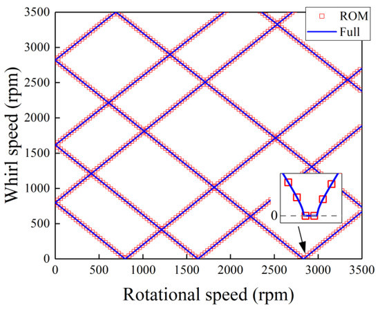
Figure 2.
The whirl speed versus rotational speed in the rotating frame.
The ROM and full FEM are also used to evaluate the gravity response of the generator rotor system in the fixed frame. The gravity response amplitude of left disk node is investigated. The results obtained by the two models are shown in Figure 3a, and the relative errors of the ROM are shown in Figure 3b. The relative error is calculated by dividing the amplitude of ROM by that of the full FEM. A total of 100 normal modes are retained in the ROM. As shown in Figure 3, the results of the ROM are in good agreement with these of full FEM. As a whole, the relative errors of the ROM are all lower than 0.1%, which validates the accuracy of the ROM. Thus, in the following analysis, the ROM with 100 normal modes retained is used to maintain the balance between calculation speed and accuracy. The resonance speeds of the gravity response are 399 rpm, 833 rpm, and 1413 rpm, respectively, which are corresponding to half of the first three critical speeds. This resonance peak of double frequency vibration is caused by the unequal principal second moments of area, which makes the vertical deflection change twice in every rotation.
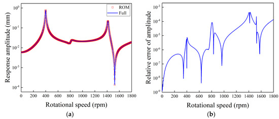
Figure 3.
The gravity response amplitude and the relative error of reduced-order model (ROM) versus rotational speed: (a) gravity response amplitude; (b) relative error.
3.2. Validation of CIM
Uncertainties in the material properties of the rotor and the supporting properties of the bearing can result in an uncertain gravity response in the generator rotor system. To validate the accuracy and efficiency of the proposed method, the results obtained by the proposed method and the scanning method are compared.
The scanning method is a straightforward method to evaluate the uncertain gravity response based on FEM. To carry out the scanning method, the interval variable is divided into a number of equidistant samples. Then, the upper bound and lower bound can be obtained from the FEM results of all the samples. The scanning method is easy to carry out, which does not involve any new algorithm. However, a large number of samples should be used to ensure the convergence of the bounds predicted by the scanning method, which limits the application of the scanning method to a high-dimensional uncertain problem. Therefore, the scanning method is used in this paper to validate the accuracy of the proposed method.
Figure 4 shows the uncertain gravity response amplitude versus the rotational speed by using the scanning method and the proposed method. The uncertain gravity response of the left disk is evaluated. In this figure, the uncertainty in the bearing’s stiffness is considered. The deviation of the bearing’s stiffness is 10%, which means that N/m. As shown in Figure 4, the results (lines) calculated by the scanning method and the results (red-filled) calculated by the proposed method are in good agreement with each other. In the application of the scanning method, 1000 equidistant samples are used. The order of Chebyshev polynomial expansion is 10, so that the number of CIM samples is 11. The samples used in the proposed method are just 1.1% of that used in the scanning method. A conclusion can be made that CIM can give an accurate prediction of an uncertain gravity response of the generator rotor system with fewer samples than the scanning method. A higher order of Chebyshev polynomial expansion can result in larger computational effort. Therefore, in the following analysis, an 11-order CIM is adopted. Under the influence of the uncertainty in the bearing’s stiffness, there is a local large-amplitude band at each resonance peak, which satisfies the phenomenon in the previous studies concerning uncertain problems [24,32]. The local large amplitude occurs when the uncertain factor that affects the resonance speed is taken into account. The resonance speed increases with the increase of the bearing’s stiffness, which contributes to the occurrence of the local large-amplitude bands in Figure 4.
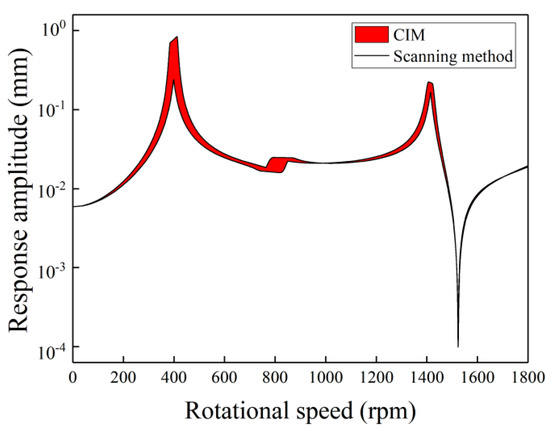
Figure 4.
The bounds of uncertain gravity response versus rotational speed by the scanning method and Chebyshev interval method (CIM) with a 10% deviation in the bearing’s stiffness.
3.3. Effect of Single Uncertainty
The other three single-uncertainty cases are studied in this section as well. The uncertainty in the bearing’s damping, Young’s modulus, and density are considered. In the three cases, the deviations of the bearing’s damping, Young’s modulus, and density are 15%, 5%, and 5%, respectively, which means Ns/m, GPa, and kg/m3.
Figure 5 shows the uncertain gravity response amplitudes versus rotational speed with single uncertainty in the bearing’s damping. As shown in Figure 5, although a larger deviation is considered, the response is slightly changed. There is no local large-amplitude band in each resonance peak. This is because the bearing’s damping can only obviously affect the response magnitude near the resonance peak, but it hardly changes the resonance speed. Therefore, tiny bounds near the resonance peaks can be observed while the response amplitudes away from the resonance peak are less influenced. Generally, when compared with the results with single uncertainty in the bearing’s stiffness, the influences of the bearing’s damping on the response are smaller.
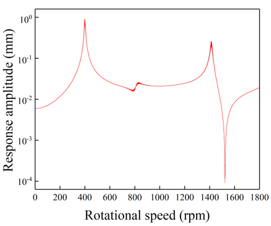
Figure 5.
The bounds of uncertain gravity response versus rotational speed by CIM with a 15% deviation in the bearing’s damping.
Figure 6 shows the uncertain gravity response amplitudes versus rotational speed with single uncertainty in Young’s modulus. Two local large-amplitude bands can be found in the first and the third resonance peaks. The width of the latter is larger than that of the former. Unlike the above-analyzed single-uncertainty cases, an obvious little-amplitude band can be found at the antiresonance position (near 1500 rpm), which shows the high sensitivity of the antiresonance position on the Young’s modulus. Besides, the response at a higher rotational speed in Figure 6 is more influenced by the Young’s modulus. The origin of this phenomenon is the resonance speed increasing with the increase of the global stiffness of the asymmetric rotor system. The global stiffness is the combination of the stiffness of the rotor and the bearing’s stiffness. As the two stiffnesses can be regarded as in series with each other, the global stiffness is more influenced by the smaller stiffness. Thus, the bearing’s stiffness can globally influence the response curve (Figure 4), while the Young’s modulus has a larger influence on the response curve near 1500 rpm (Figure 5). This is different from Figure 5, where the response at lower rotational speed is more sensitive to the bearing’s stiffness.
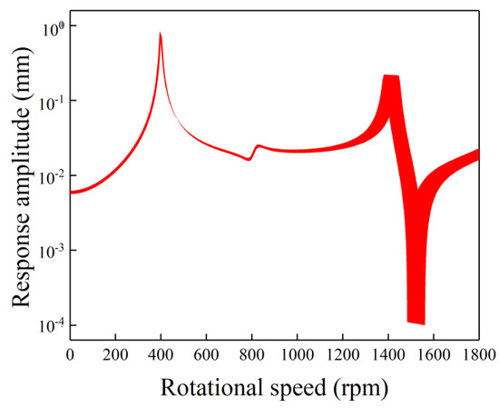
Figure 6.
The bounds of uncertain gravity response versus rotational speed by the CIM with a 5% deviation in Young’s modulus.
Figure 7 shows the uncertain gravity response amplitudes versus rotational speed with a single uncertainty in density. As the variation in density changes the whirl speed of the asymmetric rotor system, the local large-amplitude bands can be found at the first and the third resonance peaks. A higher sensitivity of the response on the density can be found at a higher rotational speed. The origin of this phenomenon is the resonance speed decreasing with the increase of the density. As the effects of the density are almost opposite to those of the Young’s modulus, the density has a larger influence on the response curve at a higher rotational speed as well. However, an obvious difference between the envelope shapes caused by the Young’s modulus and density can be observed. For example, the trends of the local large-amplitude bands at the third resonance peak of the two cases are different from each other. A conclusion can be drawn from the above analysis that different types of single uncertainty have different influences on the uncertain gravity response of the generator rotor system. Thus, in the design phase and the optimization phase, more attention should be paid to the factors with higher sensitivity.
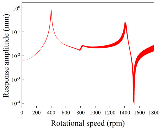
Figure 7.
The bounds of uncertain gravity response versus rotational speed by the CIM with a 5% deviation in density.
3.4. Effect of Double Uncertainties
In the generator rotor system, uncertainty may not occur alone. Thus, the uncertain gravity responses with double uncertainties are analyzed in this section. Firstly, to validate the accuracy and efficiency of the proposed method, the case with uncertainties in both the bearing’s stiffness and Young’s modulus is analyzed by the proposed method and the scanning method. The deviations in the bearing’s stiffness and Young’s modulus are 10% and 5%, respectively. Thus, the corresponding interval variables are N/m and GPa, respectively. The number of samples in the application of the scanning method is 2500. The number of samples when adopting a 10-order CIM is 121.
Figure 8 and Figure 9 show the uncertain gravity response amplitude versus rotational speed by using the scanning method and the proposed method, respectively. As shown in Figure 8, at the antiresonance position (near 1500 rpm), unexpected spurious oscillation can be found. It means that the scanning method with 2500 samples cannot give an accurate estimation of the uncertain gravity response with double uncertainties. To gain a better evaluation of the uncertain response, more samples are needed, which shows the drawback of the scanning method. As shown in Figure 9, a good agreement can be seen between the bounds obtained by the proposed method and the scanning method. Fewer samples in the proposed method can give more smooth results than those in Figure 8, which shows the efficiency and the accuracy of the proposed method. It can be found that the bounds influenced by two uncertainties are wider than those influenced by each of them individually.
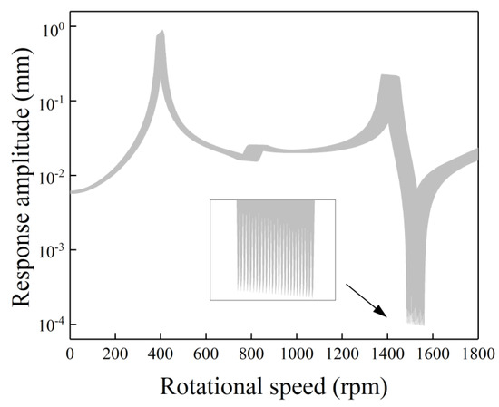
Figure 8.
The bounds of uncertain gravity response versus rotational speed by the scanning method with a 10% deviation in bearing’s stiffness and a 5% deviation in Young’s modulus.
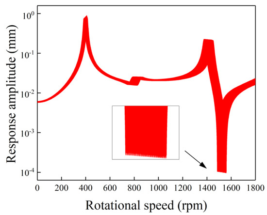
Figure 9.
The bounds of uncertain gravity response versus rotational speed by CIM with a 10% deviation in bearing’s stiffness and a 5% deviation in Young’s modulus.
Figure 10 shows the uncertain gravity response amplitudes versus rotational speed with uncertainties in the Young’s modulus and density. The deviations in Young’s modulus and density are both equal to 5%, which means GPa and kg/m3. The number of samples used in the proposed method is equal to that of the last case. Unlike the results shown in Figure 9, the uncertainties in Young’s modulus and density lead to two obvious local large-amplitude bands in the third resonance peak. Comparing with the results shown in Figure 6 and Figure 7, the first local large-amplitude band is dominated by Young’s modulus, and the second one is dominated by density. Moreover, two local small-amplitude bands in the antiresonance peak can be found. The first and the second local small-amplitude bands are dominated by density and Young’s modulus, respectively. As can be seen in the above analysis, the uncertain gravity responses of the generator rotor system with different types of double uncertainties are different from each other.
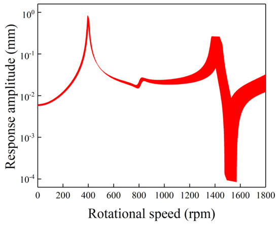
Figure 10.
The bounds of uncertain gravity response versus rotational speed by CIM with a 5% deviation in Young’s modulus and a 5% deviation in density.
4. Conclusions
In this paper, the uncertain gravity responses of the generator rotor system are evaluated by CIM. Uncertain factors regarding the bearing’s stiffness, bearing’s damping, Young’s modulus, and density are considered. The influences of these factors on the gravity response are analyzed in cases with a single uncertainty and double uncertainties. Some main conclusions are summarized as follows:
- (1)
- By comparing the results of CIM with the results of the scanning method, the accuracy and efficiency of the proposed method are validated.
- (2)
- Among the four uncertain factors considered in this paper, only the uncertainty in the bearing’s damping cannot result in a local large-amplitude band to the response curve, and the influences of it are smaller than the influences of the other three uncertain factors.
- (3)
- In terms of the local large-amplitude band, different uncertainties have different influences on the gravity response. The response at higher rotational speed is more sensitive to uncertainties in Young’s modulus and density, while the response at lower rotational speed is more sensitive to the bearing’s stiffness.
- (4)
- The bounds influenced by two uncertainties are wider than that influenced by each of them. Two uncertainties can introduce two local large-amplitude bands to one resonance peak.
- (5)
- The sensitivities of uncertain factors obtained by the proposed method can provide guidance to the design and optimization of the rotary machinery.
Author Contributions
Conceptualization, Z.Z., Y.X. and D.Z.; Methodology, Z.Z., Y.X. and D.Z.; Software, Z.Z.; Validation, Y.X.; Writing—original draft, Z.Z. and Y.X.; Writing—review & editing, D.Z.
Funding
This work is supported by Research Program supported by the 111 project (B16038), China.
Conflicts of Interest
The authors declare no conflict of interest.
References
- Huang, S.; Liu, Z.; Su, J. On Double Frequency Vibration of a Generator-Bearing System With Asymmetrical Stiffness. In In Proceedings of the ASME 2002 International Mechanical Engineering Congress and Exposition, New Orleans, LA, USA, 17–22 November 2002. [Google Scholar]
- Liu, C.; Jiang, D. Dynamics of Slant Cracked Rotor for a Steam Turbine Generator System. J. Eng. Gas Turbines Power 2017, 139, 062502. [Google Scholar] [CrossRef]
- Shuai, W.; Zi, Y.Y.; Wang, Y.; He, Z.J. A 3D nonlinear finite element method for the dynamic analysis of rotating rotor with a transverse crack. Sci. China Technol. Sci. 2017, 60, 219–231. [Google Scholar]
- Al-Shudeifat, M.A. New backward whirl phenomena in intact and cracked rotor systems. J. Sound Vib. 2019, 443, 124–138. [Google Scholar] [CrossRef]
- Spagnol, J.P.; Wu, H.; Xiao, K. Dynamic response of a cracked rotor with an unbalance influenced breathing mechanism. J. Mech. Sci. Technol. 2018, 32, 57–68. [Google Scholar] [CrossRef]
- Peletan, L.; Sébastien, B.; Torkhani, M.; Jacquet-Richardet, G. A comparison of stability computational methods for periodic solution of nonlinear problems with application to rotordynamics. Nonlinear Dyn. 2013, 72, 671–682. [Google Scholar] [CrossRef]
- Leung, A.Y.T.; Fung, T.C. Spinning finite elements. J. Sound Vib. 1988, 125, 523–537. [Google Scholar] [CrossRef]
- Jei, Y.G.; Lee, C.W. Finite element model of asymmetrical rotor-bearing systems. KSME J. 1988, 2, 116–124. [Google Scholar] [CrossRef]
- Kang, Y.; Shih, Y.P.; Lee, A.C. Investigation on the Steady-State Responses of Asymmetric Rotors. J. Vib. Acoust. 1992, 114, 194–208. [Google Scholar] [CrossRef]
- Rao, J.S. Dynamics of asymmetric rotors using solid models. In Proceedings of the International Gas Turbine Congress, Tokyo, Japan, 2–7 November 2003. [Google Scholar]
- Lazarus, A.; Prabel, B.; Combescure, D. A 3D finite element model for the vibration analysis of asymmetric rotating machines. J. Sound Vib. 2010, 329, 3780–3797. [Google Scholar] [CrossRef]
- Wang, S.; Zi, Y.Y.; Wang, Y.; He, Z.J. A 3D finite element-based model order reduction method for parametric resonance and whirling analysis of anisotropic rotor-bearing systems. J. Sound Vib. 2015, 359, 116–135. [Google Scholar] [CrossRef]
- Meng, M.W.; Jun, W.J.; Zhi, W. Frequency and Stability Analysis Method of Asymmetric Anisotropic Rotor-Bearing System Based on Three-Dimensional Solid Finite Element Method. J. Eng. Gas Turbines Power 2015, 137, 102502. [Google Scholar] [CrossRef]
- Zuo, Y.; Wang, J.; Ma, W. Quasimodes instability analysis of uncertain asymmetric rotor system based on 3D solid element model. J. Sound Vib. 2017, 390, 192–204. [Google Scholar] [CrossRef]
- Zheng, Z.; Zhu, F.; Zhang, D.; Xie, Y. A developed component mode synthesis for parametric response analysis of large-scale asymmetric rotor. J. Mech. Sci. Technol. 2019, 33, 995–1005. [Google Scholar] [CrossRef]
- Didier, J.; Faverjon, B.; Sinou, J.J. Analysing the dynamic response of a rotor system under uncertain parameters by polynomial chaos expansion. J. Vib. Control 2012, 18, 712–732. [Google Scholar] [CrossRef]
- Didier, J.; Sinou, J.J.; Faverjon, B. Nonlinear vibrations of a mechanical system with non-regular nonlinearities and uncertainties. Commun. Nonlinear Sci. Numer. Simul. 2013, 18, 3250–3270. [Google Scholar] [CrossRef]
- Sinou, J.J.; Didier, J.; Faverjon, B. Stochastic non-linear response of a flexible rotor with local non-linearities. Int. J. Non-Linear Mech. 2015, 74, 92–99. [Google Scholar] [CrossRef]
- Sinou, J.J.; Jacquelin, E. Influence of Polynomial Chaos expansion order on an uncertain asymmetric rotor system response. Mech. Syst. Signal Process. 2015, 50–51, 718–731. [Google Scholar] [CrossRef]
- Rao, S.S.; Berke, L. Analysis of Uncertain Structural Systems Using Interval Analysis. Aiaa. J. 1997, 35, 727–735. [Google Scholar] [CrossRef]
- Qiu, Z.; Wang, X. Comparison of dynamic response of structures with uncertain-but-bounded parameters using non-probabilistic interval analysis method and probabilistic approach. Int. J. Solids Struct. 2003, 40, 5423–5439. [Google Scholar] [CrossRef]
- Qiu, Z.; Wang, X. Parameter perturbation method for dynamic responses of structures with uncertain-but-bounded parameters based on interval analysis. Int. J. Solids Struct. 2005, 42, 4958–4970. [Google Scholar] [CrossRef]
- Wu, J.; Luo, Z.; Zhang, Y.; Zhang, N.; Chen, L. Interval uncertain method for multibody mechanical systems using Chebyshev inclusion functions. Int. J. Numer. Methods Eng. 2013, 95, 608–630. [Google Scholar] [CrossRef]
- Fu, C.; Ren, X.; Yang, Y.; Lu, K.; Wang, Y. Nonlinear response analysis of a rotor system with a transverse breathing crack under interval uncertainties. Int. J Non-Linear Mech. 2018, 105, 77–87. [Google Scholar] [CrossRef]
- Fu, C.; Ren, X.; Yang, Y.; Lu, K.; Qin, W. Steady-state response analysis of cracked rotors with uncertain-but-bounded parameters using a polynomial surrogate method. Commun. Nonlinear Sci. Numer. Simul. 2019, 68, 240–256. [Google Scholar] [CrossRef]
- Wei, S.; Zhao, J.; Han, Q.; Chu, F. Dynamic response analysis on torsional vibrations of wind turbine geared transmission system with uncertainty. Renew. Energy 2015, 78, 60–67. [Google Scholar] [CrossRef]
- Wei, S.; Han, Q.K.; Dong, X.J.; Peng, Z.K.; Chu, F.L. Dynamic response of a single-mesh gear system with periodic mesh stiffness and backlash nonlinearity under uncertainty. Nonlinear Dyn. 2017, 89, 49–60. [Google Scholar] [CrossRef]
- Zheng, Z.; Jing, Q.; Xie, Y.; Zhang, D. An Investigation on the Forced Convection of Al2O3-water Nanofluid Laminar Flow in a Microchannel Under Interval Uncertainties. Appl. Sci. Basel 2019, 9, 13. [Google Scholar] [CrossRef]
- Wang, C. Interval analysis of steady-state heat convection–diffusion problem with uncertain-but-bounded parameters. Int. J. Heat Mass Transf. 2015, 91, 355–362. [Google Scholar] [CrossRef]
- Wang, C.; Qiu, Z.; Xu, M. Collocation methods for fuzzy uncertainty propagation in heat conduction problem. Int. J. Heat Mass Transf. 2017, 107, 631–639. [Google Scholar] [CrossRef]
- Bampton, M.; Craig, R. Coupling of substructures for dynamic analyses. Aiaa. J. 1968, 6, 1313–1319. [Google Scholar] [CrossRef]
- Fu, C.; Ren, X.; Yang, Y.; Qin, W. Dynamic response analysis of an overhung rotor with interval uncertainties. Nonlinear Dyn. 2017, 89, 2115–2124. [Google Scholar] [CrossRef]
© 2019 by the authors. Licensee MDPI, Basel, Switzerland. This article is an open access article distributed under the terms and conditions of the Creative Commons Attribution (CC BY) license (http://creativecommons.org/licenses/by/4.0/).