Article

Fault Diagnosis of Induction Motor Using Convolutional Neural Network

School of Electronics Engineering, Kyungpook National University, Daegu 41566, Korea
*
Author to whom correspondence should be addressed.
Appl. Sci. 2019, 9(15), 2950; https://doi.org/10.3390/app9152950
Submission received: 4 June 2019 / Revised: 4 July 2019 / Accepted: 22 July 2019 / Published: 24 July 2019
(This article belongs to the Special Issue Fault Diagnosis of Rotating Machine)

Abstract

:
Induction motors are among the most important components of modern machinery and industrial equipment. Therefore, it is necessary to develop a fault diagnosis system that detects the operating conditions of and faults in induction motors early. This paper presents an induction motor fault diagnosis system based on a CNN (convolutional neural network) model. In the proposed method, vibration signal data are obtained from the induction motor experimental environment, and these values are input into the CNN. Then, the CNN performs fault diagnosis. In this study, fault diagnosis of an induction motor is performed in three states, namely, normal, rotor fault, and bearing fault. In addition, a GUI (graphical user interface) for the proposed fault diagnosis system is presented. The experimental results confirm that the proposed method is suitable for diagnosing rotor and bearing faults of induction motors.

1. Introduction

Induction motors are among the most important components for driving DC motors, rectifiers and DC motor systems, and industrial equipment. However, plant shutdowns because of unexpected induction motor faults cause significant economic losses. Therefore, it is necessary to develop a fault diagnosis system that detects the operating conditions of and faults in induction motors early [1].
Fault diagnosis involves detecting faults in the system and classifying them. Fault diagnosis methods are broadly classified into model-based methods and non-model-based methods. In model-based methods, system faults are diagnosed using a mathematical model of the system, but it is not easy to obtain an accurate mathematical model owing to system nonlinearity. Non-model-based methods include fault diagnosis based on measurements, experience, or physical reviews of the target system, as well as thresholding, expert system techniques, and neural networks [2].
Faults in an induction motor are diagnosed mainly by using characteristic motor signals, such as vibration signals, motor currents [3,4,5,6,7,8,9], acoustic signals [10], and thermal images [11]. In the method that employs vibration signals [3,4,5], the vibration signals generated by an induction motor are measured, and fault diagnosis is performed by frequency analysis of the measured signals. In the method that employs motor current [6,7,8], a fixed magnetic current is obtained, and fault diagnosis is performed by frequency analysis of the measured signals. In the method that employs acoustic signals, the acoustic signals generated by an induction motor are measured, and fault diagnosis is performed by frequency analysis of the measured signals. In the method that employs thermal images, thermal images of an induction motor are acquired, and fault diagnosis is performed using features extracted from the images. Lee [1] proposed a fault diagnosis method for induction motors based on discrete wavelet transform and ART2 NN (adaptive resonance theory 2 neural network) with uneven vigilance parameters. This method is composed of a data preprocessing part by frequency analysis of vibration signals and a fault classification part for fault isolation by using ART2 NN. However, this method requires data conversion from the time domain into the frequency domain.
In recent years, NN (neural network) models have been studied extensively for application to fault diagnosis [12,13,14]. The structure of these models is suitable for representing unknown nonlinear functions in a general manner. Therefore, NN models can be used as a powerful tool for solving nonlinear problems. However, a neural network model with perfect connection layers cannot learn invariant properties. Consequently, it cannot be learnt by extracting effective features from periodic vibration signals [15].
In this study, a CNN (convolutional neural network) model with local connectivity is used for fault diagnosis. The vibration signals of three states, namely, normal, rotor fault, and bearing fault, are obtained from an induction motor and used for fault classification. In addition, a GUI (graphical user interface) is implemented to enable users to diagnose induction motor faults efficiently and intuitively. The performance of the proposed fault diagnosis method is verified through an experiment and a simulation.

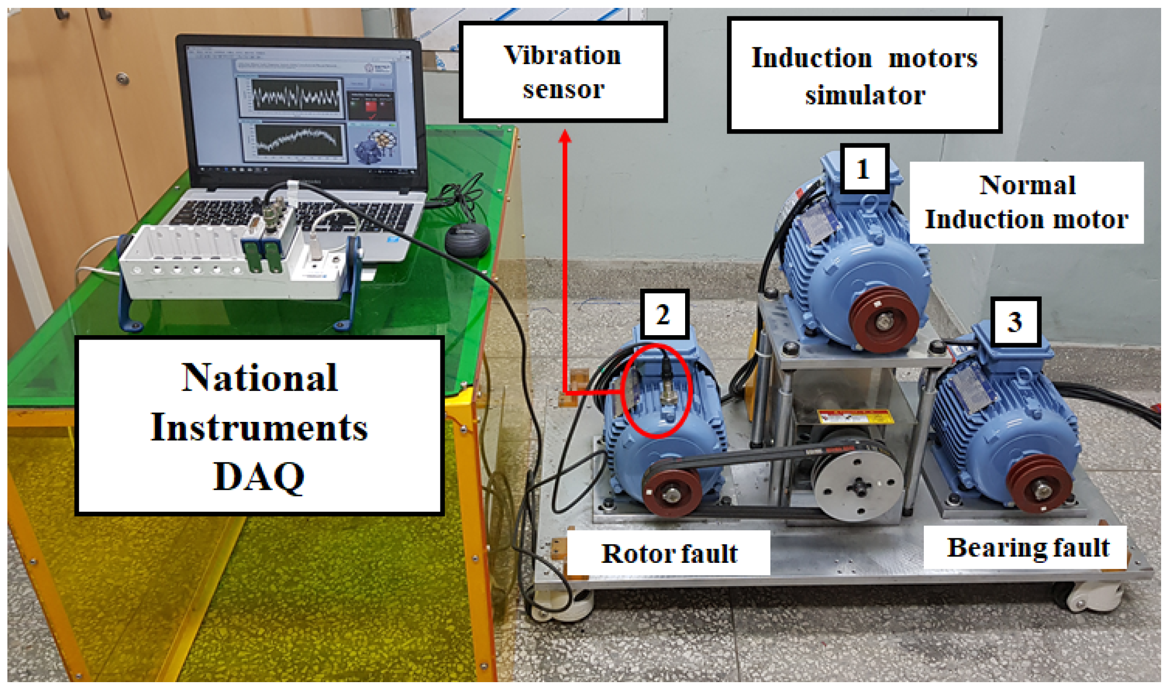
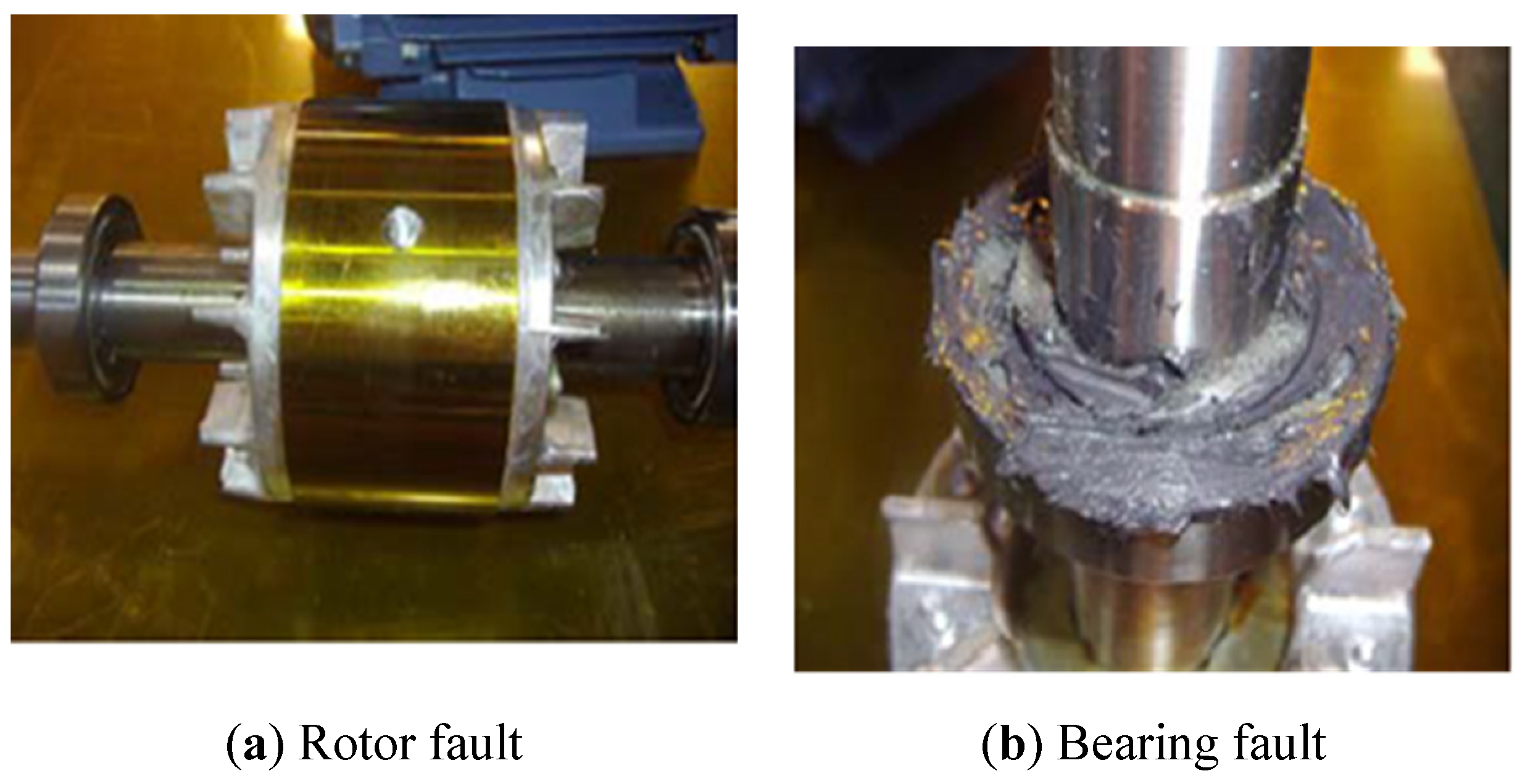
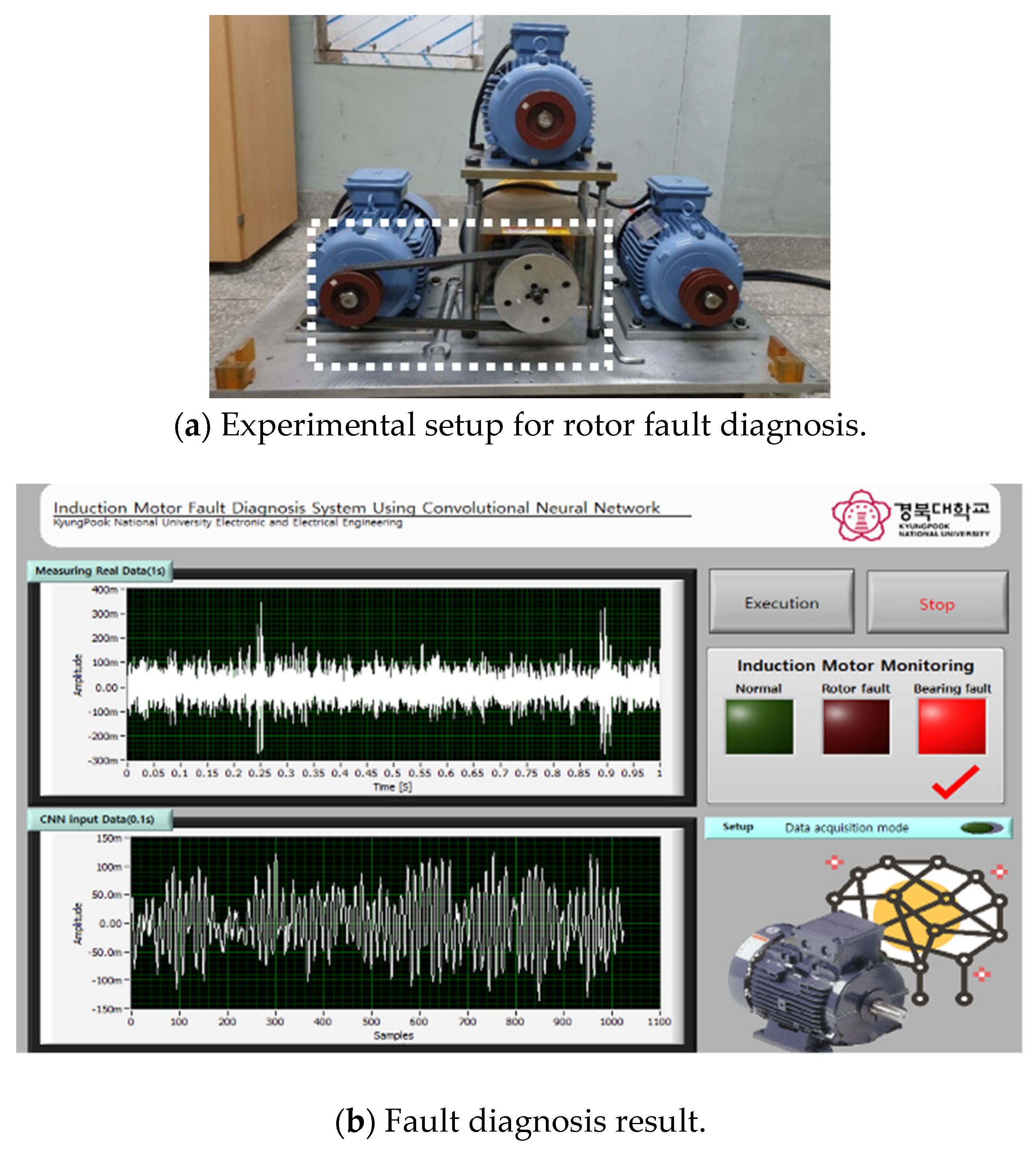
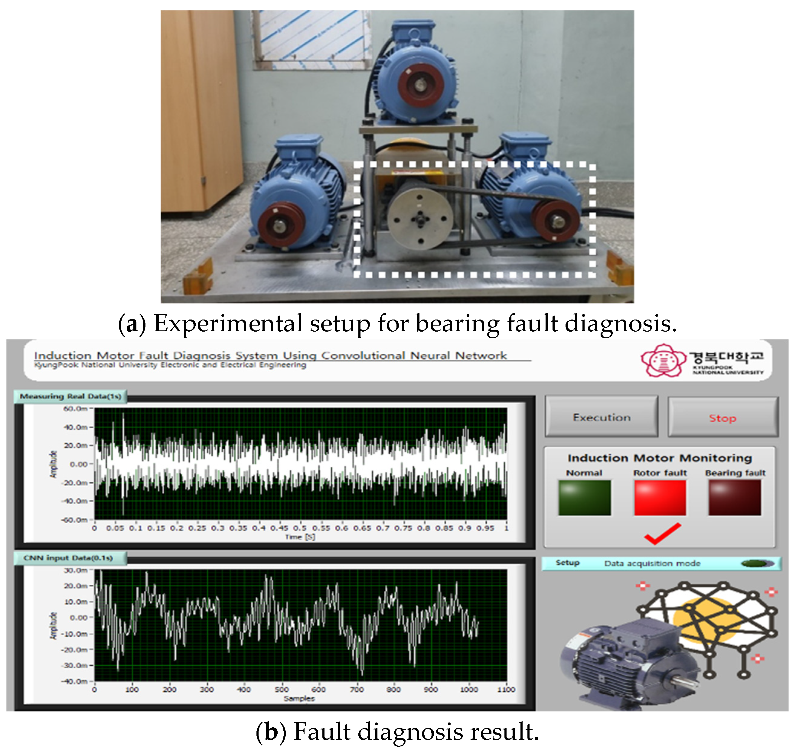
2. Experimental Environment for Fault Diagnosis of Induction Motor

For fault diagnosis of induction motors, a simulator was constructed by using three three-phase induction motor to produce three states, namely, normal, rotor fault, and bearing fault, as shown in Figure 1. Figure 1-① shows an induction motor in the normal state, Figure 1-② an induction motor with rotor fault, and Figure 1-③ an induction motor with bearing fault. We acquired vibration data from these induction motors by using a vibration sensor and NI-9234 (National Instruments, TX, USA). The specifications of the induction motors used herein are shown in Table 1, and all three induction motors have the same specifications.
As shown in Figure 2, two types of faults occur in induction motors: rotor fault and bearing fault. As shown in Figure 2a, the rotor bar of the induction motor is punctured with a drill, and the bearing is worn by inserting powder into it, as shown in Figure 2b.

3. Proposed Fault Diagnosis Method for Induction Motors

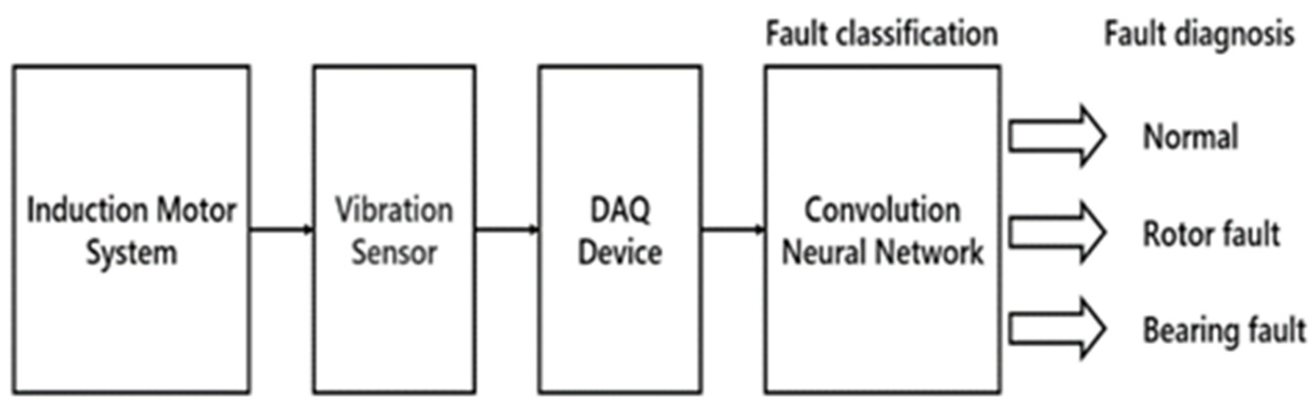
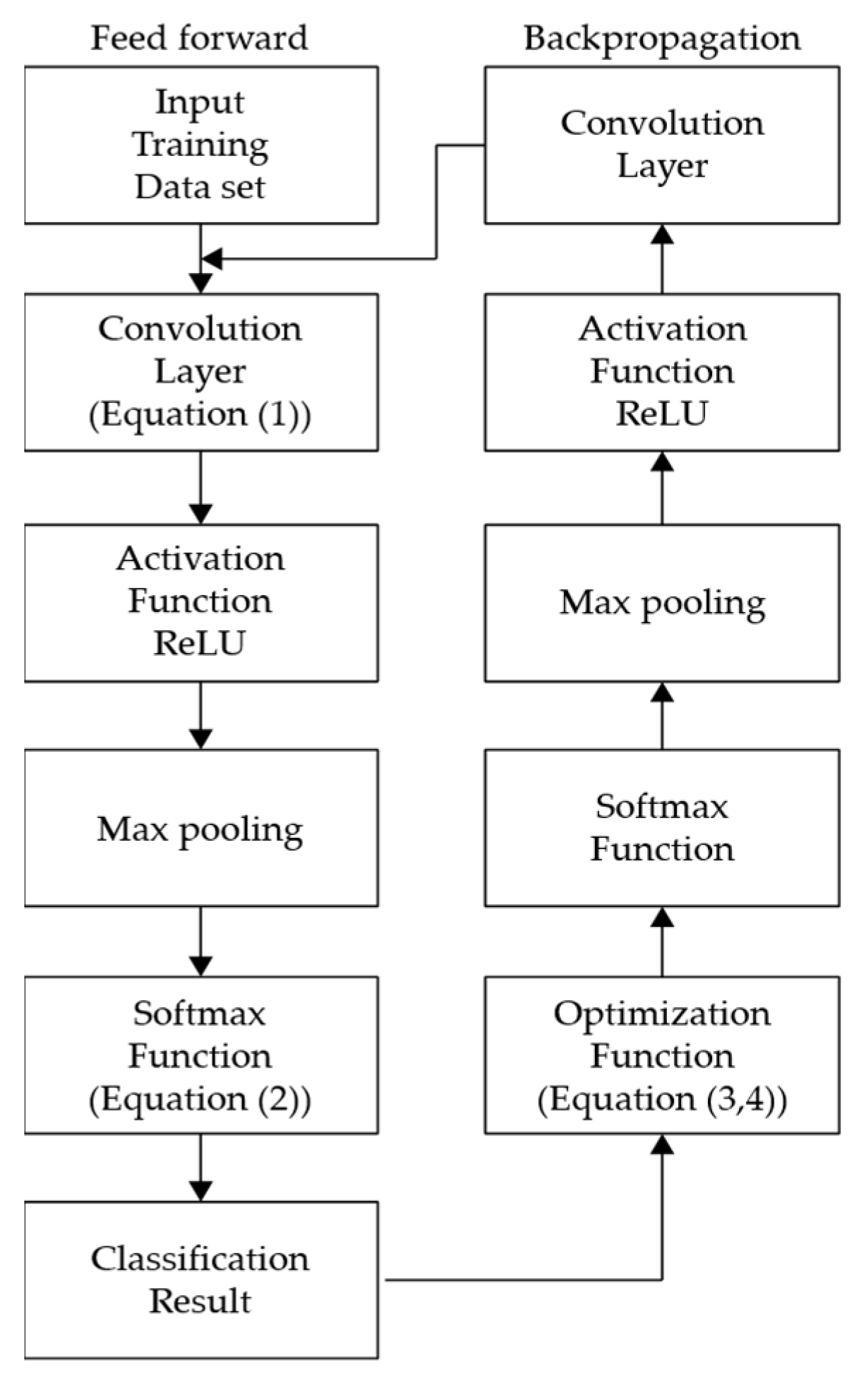
3.1. CNN-Based Fault Diagnosis System

The proposed fault diagnosis system consists of a vibration sensor for measuring the vibration signals generated by an induction motor, as shown in Figure 3; data collection part for digitizing and storing the vibration signals obtained from the vibration sensor; and a CNN-based fault classification unit that classifies the types of faults generated in the induction motor. The CNN model receives vibration data obtained from the induction motor and classifies them into three states, namely, normal, rotor fault, and bearing fault. In addition, a GUI was developed using LabVIEW to enable users to diagnose faults of induction motors efficiently and intuitively.

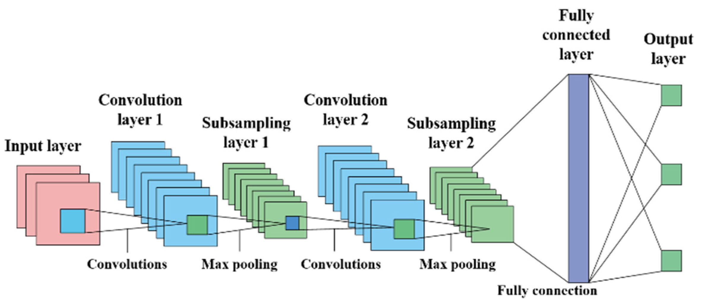
3.2. Convolutional Neural Network

A CNN model integrates feature extraction and classification, which is different from existing pattern-recognition methods. A CNN is composed of a plurality of convolutional layers and a subsampling layer [16,17]. The CNN used in the proposed induction motor fault detection system consists of one input layer, two convolutional layers, two max pooling layers and one fully connected layer, and three output layers, as shown in Figure 4.
The convolutional layer uses the kernel to convolve the input data and then passes the activation function to generate an output feature map. Considering the convolutional layer is the l -th layer, its output feature map is as follows:
x j l = f ( i x i l 1 k i j l + b j l ) ,
where x j l is the j -th feature map generated by the l -th layer, and x j l 1 is the i -th input feature map. The input feature map is a specific input data pattern, k j j l is the j -th kernel connected to the i -th input feature map, f( ) is the activation function, b j l is the bias corresponding to the j -th kernel, and * is the two-dimensional convolution operation [18].
The subsampling layer reduces the dimension of the extracted feature map. Various techniques are available for pooling. In the present study, the max pooling method, which extracts the maximum value from a feature map, is used. The max pooling technique reduces the size of the entire data, which reduces the computational cost and helps extract only the necessary data [19].
In CNN, when the convolutional layer and the max pooling layer are repeated, only the main features are extracted, and the extracted features are transmitted to the fully connected layer. As the convolutional layer and the max pooling layer contain two-dimensional data, they are transformed into one-dimensional layers for transmission to the fully connected layer and subsequent transfer to the output layer.
The softmax function is used as the cost function to transform the class classification problem, that is, the output of the previous layer, into the probability of each state when solving the state classification problem. The softmax function is as follows [20]:
y l = e a l i = 1 n e a i ,
where n is number of output neurons, and y l is the l -th output. The numerator is an exponential function of the input data e a l , and the denominator is the sum of all input data. Take the exponent on each output and divide by the normalization constant so that the sum is 1.
The optimization function of the proposed CNN model uses RMSprop. The RMSprop algorithm does not uniformly add all past gradients but reflects the information of only the new gradient so that the learning rate does not decrease to 0 [21]. The algorithm is given as follows:
G t = γ G + ( 1 γ ) ( θ f t ( θ t ) ) 2 ,
θ t = θ t 1 η G t ϵ · θ f t ( θ t 1 ) ,
where γ is the forgetting factor, typically 0.9. θ is a network parameter, and f ( θ ) is the cost function. In this study, the softmax function is used. θ f ( θ ) is the network gradient. t is the time step, and if the network parameter is k, Gt is a k-dimensional vector that stores the sum of the squares of the gradient to which each variable moves until time step t. η is the learning rate. In this study, the learning rate was set to 0.001. ϵ is a small value ranging from 10−4 to 10−8 to prevent division by 0. Figure 5 shows a block diagram of the learning process for CNN.

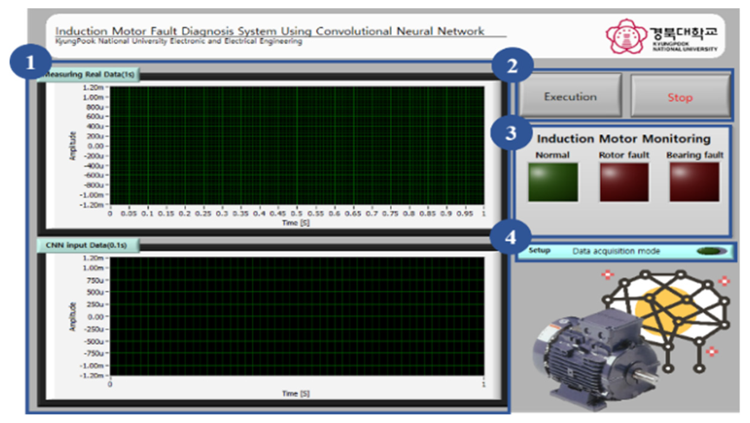
3.3. GUI of Fault Diagnosis System

The PC GUI of the induction motor fault diagnosis system described in this paper is shown in Figure 6. The GUI program uses LabVIEW.
Figure 6-① shows the GUI window for real-time monitoring of the vibration data obtained from the induction motor. The upper graph shows the vibration data obtained from the induction motor per second, and the lower graph shows the data converted to 1024 (0.1 s) so that they can be input into the CNN.
Figure 6-② shows the execution and stop buttons of the induction motor fault diagnosis system. When the execution button is pressed, 1024 data samples are extracted from the measured vibration data. The extracted data are input into the CNN model. Then, the fault diagnosis program is executed. The result is displayed in Figure 6-③.
Figure 6-③ shows the results of the induction motor fault diagnosis system and indicates whether the motor is in the normal state, rotor fault state, or bearing fault state.
Figure 6-④ shows the button to set the induction motor fault diagnosis system mode. When the button is pressed, data acquisition mode is executed, and induction motor data can be collected into an Excel file. When the button is clicked again, the data collection mode is terminated, and the fault diagnosis mode is executed again.

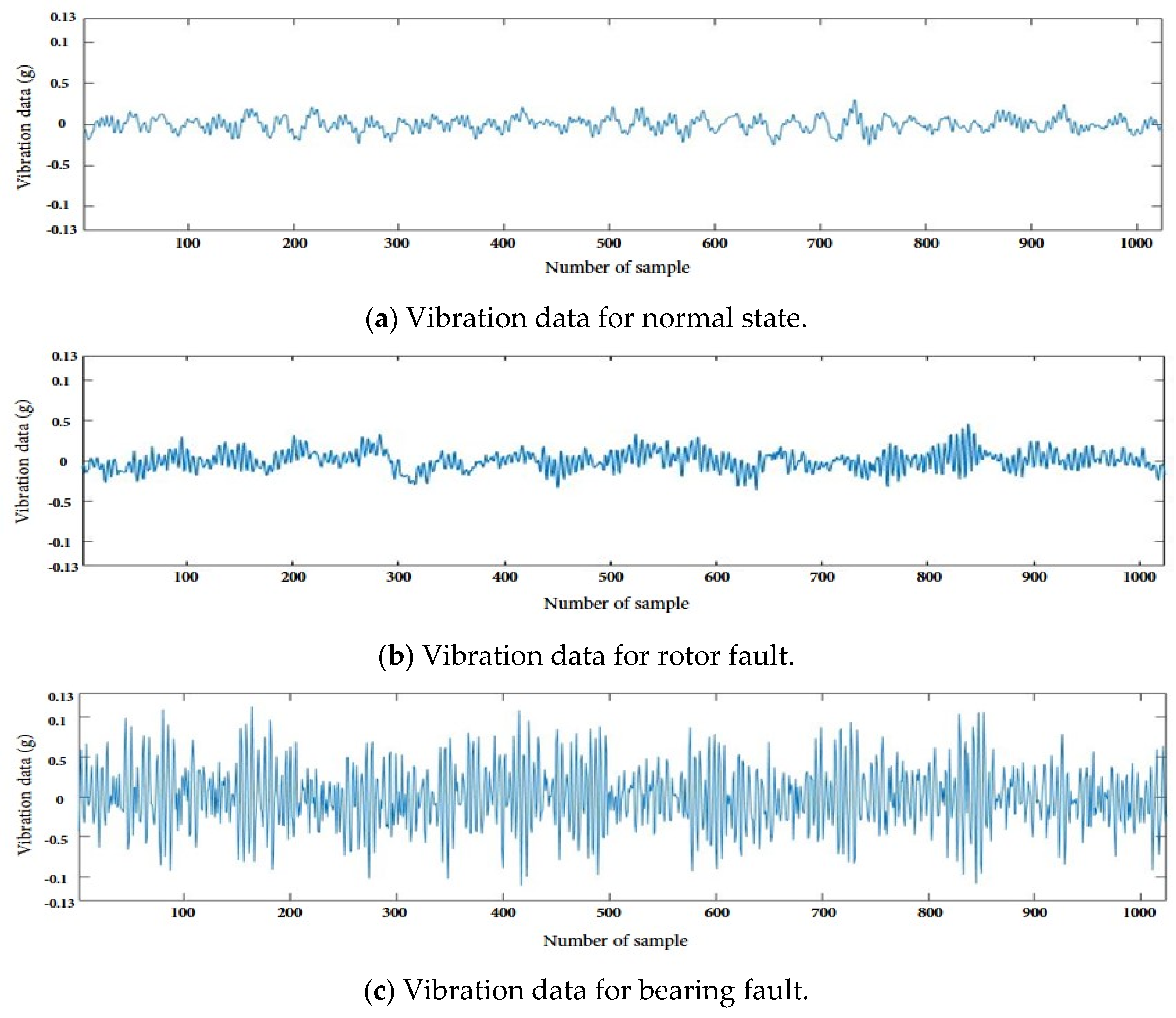
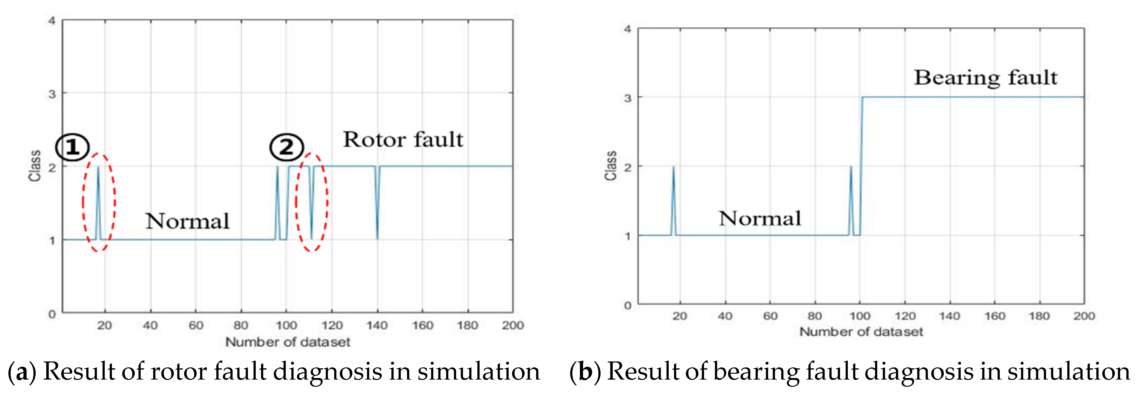
4. Experiment and Results

The simulation and experiment environments were implemented using Python 3.5 and the Keras library in Windows 10 OS. To verify the performance of the proposed induction motor fault diagnosis system, vibration signals obtained from the induction motors shown in Figure 1 were used as the test data. The composition of the proposed CNN model was as follows. Convolutional layer 1 consisted of 64 filters with a size of 5 × 5, and convolutional layer 2 consisted of 32 filters with a size of 3 × 3. The max pooling layer measured 2 × 2 in size. The fully connected layer consisted of 256 nodes, and the output layer consisted of three nodes. The number of CNN inputs was 1024, and the number of CNN outputs was three. To test the performance of the proposed induction motor fault diagnosis system, vibration signal data were acquired using a vibration sensor by artificially generating normal, rotor fault, and bearing fault states in the experimental apparatus, as shown in Figure 7a–c, respectively. Table 2 shows the numbers of normal, rotor fault, and bearing fault data used for training and testing. A total of 200 datasets were used to train the CNN, and 100 datasets were used to test the CNN. Each dataset contained 1024 data samples. The parameter settings for CNN training were as follows: η = 0.001, ε = 10−8, iteration epoch for CNN training = 30. The vibration data used for training the CNN were not subjected to frequency domain transformation.
Figure 8 shows the test results obtained in two cases of fault diagnosis when the inverter changes from the normal state to the rotor fault state and when the inverter changes from the normal state to the bearing fault state. In Figure 8, the x-axis represents the number of vibration data, and the y-axis represents the fault class. Classes 1, 2, and 3 represent the normal, rotor fault, and bearing fault states. A total of 300 datasets were used in the test, including 100 datasets each for the normal, rotor fault, and bearing fault states. The simulation proceeded as follows. First, after inputting 100 pairs of normal data, rotor fault data and bearing fault states were input. Figure 8a shows the simulation results obtained using the rotor fault data. Figure 8a-① shows misclassification of the simulation data of the normal state as rotor fault state; two instances of this misclassification occurred in total. Figure 8a-② shows misclassification of the rotor fault state simulation data as normal state; two instances of this misclassification occurred in total. Figure 8b shows the simulation results of bearing fault data. All bearing fault test data were classified correctly.
Accordingly, as shown in Table 3, the accuracies of fault diagnosis of the normal, rotor fault, and bearing fault states are 98%, 98%, and 100%, respectively.
In addition, we demonstrated the use GUI to determine whether an induction motor has a rotor fault or bearing fault, as in Figure 9a and Figure 10a, respectively. Figure 8 shows the result of rotor fault diagnosis of an induction motor in a real environment. Figure 9a shows the induction motor with a rotor fault used in the test. The fault diagnosis result obtained with the proposed fault diagnosis system is shown in Figure 9b. Figure 10 shows the diagnosis result of bearing fault of an induction motor in a real environment. Figure 10a shows the induction motor with a bearing fault used in the test, and Figure 10b shows the bearing fault in the LED, indicating the output of the fault diagnosis system. The experimental results show that the proposed fault diagnosis system can accurately diagnose faults even in a real environment.

5. Conclusions

In this paper, an induction motor fault diagnosis system based on a CNN is proposed. In the proposed method, fault diagnosis of an induction motor is performed by inputting the data obtained from a simulator into the CNN. As a result, we could confirm that the motor state was diagnosed accurately from the motor data obtained using the simulator and that fault diagnosis can be performed without frequency domain transformation. In this study, fault diagnosis of an induction motor was performed in three states, namely, normal, rotor fault, and bearing fault. The experimental results confirm that the proposed method is suitable for diagnosing rotor and bearing faults of induction motors. In addition, a GUI for fault diagnosis was developed and applied to a real environment. In the real environment, the accuracy of the fault diagnosis system was 98%, 98%, and 100% for the normal, rotor fault, and bearing fault states of induction motors.
The proposed induction motor fault diagnosis system is expected to contribute to the maintenance of facilities and reduce costs by preliminarily estimating the existence of a fault in a real plant. The performance of the system was verified through experiments on real data obtained using a simulator. It is expected that the fault diagnosis technology developed in this study will be applicable to similar systems and devices. In the future, studies will be conducted to apply the proposed method to industrial equipment.

Author Contributions

Methodology, J.-H.L. and I.-S.L.; Investigation, J.-H.L., J.-H.P. and I.-S.L.; Experiments, J.-H.L. and J.-H.P.; Data analysis, J.-H.L. and I.-S.L.; Writing-original draft, J.-H.L.; Writing-review & editing, I.-S.L.

Funding

This research was supported by Basic Science Research Program through the National Research Foundation of Korea (NRF) funded by the Ministry of Education (No. 2019R1I1A3A01058319). Additionally, this study was supported by the BK21 Plus project funded by the Ministry of Education, Korea (21A20131600011).

Conflicts of Interest

The authors declare no conflict of interest.

References

  1. Lee, I.S. Fault Diagnosis System Development of Induction Motors Using Discrete Wavelet Transform and Neural Network. J. Korean Inst. Inf. Technol. 2018, 9, 53–61. [Google Scholar] [CrossRef]
  2. Lee, I.S. Fault Diagnosis of Induction Motors Using Discrete Wavelet Transform and Artificial Neural Network. In Proceedings of the International Conference on Human-Computer Interaction, Orlando, FL, USA, 9–14 July 2011; pp. 9–14. [Google Scholar]
  3. Vas, P. Parameter Estimation, Condition Monitoring, and Diagnosis of Electrical Machines; Oxford Science; Oxford University Press: Oxford, UK, 1993. [Google Scholar]
  4. Li, B.; Chow, M.Y.; Tipsuwan, Y.; Hung, J.C. Neural-network-based motor rolling bearing fault diagnosis. IEEE Trans. Ind. Electron. 2000, 47, 1060–1069. [Google Scholar] [CrossRef]
  5. Schoen, R.R.; Habetler, T.G.; Kamran, F.; Bartfield, R.G. Motor bearing damage detection using stator current monitoring. IEEE Trans. Ind. Appl. 1995, 31, 1274–1279. [Google Scholar] [CrossRef]
  6. Schoen, R.R.; Lin, B.K.; Habetler, T.G.; Schlag, J.H.; Farag, S. An unsupervised, on-line system for induction motor fault detection using stator current monitoring. IEEE Trans. Ind. Appl. 1995, 31, 1280–1286. [Google Scholar] [CrossRef]
  7. Ye, Z.; Wu, B.; Sadeghian, A. Current signature analysis of induction motor mechanical faults by wavelet packet decomposition. IEEE Trans. Ind. Electron. 2003, 50, 1217–1228. [Google Scholar]
  8. Calis, H.; Cakir, A. Experimental study for sensorless broken bar detection in induction motors. Energy Convers. Manag. 2008, 49, 854–862. [Google Scholar] [CrossRef]
  9. De Santiago-Perez, J.J.; Rivera-Guillen, J.R.; Amezquita-Sanchez, J.P.; Valtierra-Rodriguez, M.; Romero-Troncoso, R.J.; Dominguez-Gonzalez, A. Fourier transform and image processing for automatic detection of broken rotor bars in induction motors. Meas. Sci. Technol. 2018, 29, 095008. [Google Scholar] [CrossRef]
  10. Glowacz, A. Acoustic based fault diagnosis of three-phase induction motor. Appl. Acoust. 2018, 137, 82–89. [Google Scholar] [CrossRef]
  11. Glowacz, A.; Glowacz, Z. Diagnosis of the three-phase induction motor using thermal imaging. Infrared Phys. Technol. 2017, 81, 7–16. [Google Scholar] [CrossRef]
  12. Polycarpou, M.M.; Vemuri, A.T. Learning methodology for failure detection and accommodation. IEEE Control. Syst. Mag. 1995, 15, 16–24. [Google Scholar]
  13. Srinivasan, A.; Batur, C. Hopfield/ART-1 neural network-based fault detection and isolation. IEEE Trans. Neural Netw. 1994, 5, 890–899. [Google Scholar] [CrossRef] [PubMed]
  14. Lee, I.S.; Shin, P.J.; Jeon, G.J. Multiple faults diagnosis of a linear system using ART2 neural networks. J. Inst. Control Robot. Syst. 1997, 3, 244–251. [Google Scholar]
  15. Lee, I.S. Diagnostic system development for state monitoring of induction motor and oil level in press process system. J. Korean Inst. Intell. Syst. 2009, 19, 706–712. [Google Scholar] [CrossRef]
  16. Agarap, A.F. An architecture combining convolutional neural network (CNN) and support vector machine (SVM) for image classification. arXiv 2017, arXiv:1712.03541. [Google Scholar]
  17. Sun, W.; Zhao, R.; Yan, R.; Shao, S.; Chen, X. Convolutional discriminative feature learning for induction motor fault diagnosis. IEEE Trans. Ind. Inform. 2017, 13, 1350–1359. [Google Scholar] [CrossRef]
  18. Dasgupta, A.; Singh, S. A fully convolutional neural network based structured prediction approach towards the retinal vessel segmentation. In Proceedings of the 2017 IEEE 14th International Symposium on Biomedical Imaging, Melbourne, Australia, 18–21 April 2017; pp. 248–251. [Google Scholar]
  19. Zhao, R.; Yan, R.; Chen, Z.; Mao, K.; Wang, P.; Gao, R.X. Deep learning and its applications to machine health monitoring. Mech. Syst. Signal Process. 2019, 115, 213–237. [Google Scholar] [CrossRef]
  20. Tao, S.; Zhang, T.; Yang, J.; Wang, X.; Lu, W. Bearing fault diagnosis method based on stacked autoencoder and softmax regression. In Proceedings of the 2015 34th Chinese Control Conference, Hangzhou, China, 28–30 July 2015; pp. 6331–6335. [Google Scholar]
  21. Tieleman, T.; Hinton, G. Lecture 6.5-rmsprop: Divide the gradient by a running average of its recent magnitude. COURSERA Neural Netw. Mach. Learn. 2012, 4, 26–31. [Google Scholar]
Figure 1. Experimental setup.
Applsci 09 02950 g001
Figure 2. Fault types of induction motor.
Applsci 09 02950 g002
Figure 3. Block diagram of proposed fault diagnosis method.
Applsci 09 02950 g003
Figure 4. Structure of proposed CNN (convolutional neural network) model.
Applsci 09 02950 g004
Figure 5. Block diagram of learning process.
Applsci 09 02950 g005
Figure 6. GUI (graphical user interface) screen in LabVIEW.
Applsci 09 02950 g006
Figure 7. Experimental data.
Applsci 09 02950 g007
Figure 8. Result of induction motor fault diagnosis in simulation.
Applsci 09 02950 g008
Figure 9. Diagnosis results for rotor fault in real environment.
Applsci 09 02950 g009
Figure 10. Diagnosis results for bearing fault in real environment.
Applsci 09 02950 g010
Table 1. Specifications of induction motor used herein.
Model NumberHL105AL202T1
Rated Power2.2 Kw (3 HP)
Rated Current8.6/5.0 A
Rated Speed1730 rpm
Frequency60 Hz
Voltage3 Phase 380 V
Table 2. The dataset for simulation.
Induction Motor StateNumber of Learning DatasetsNumber of Test Datasets
Normal200100
Rotor fault200100
Bearing fault200100
Total600300
Table 3. Accuracy of test.
Test Data TypeClassification Results
NormalRotor FaultBearing Fault
Normal98%2%0%
Rotor fault2%98%0%
Bearing fault0%0%100%

