Article

Blistering Mechanism Analysis of Hydraulic Asphalt Concrete Facing

1
Division of Materials, China Institute of Water Resources and Hydropower Research (IWHR), Beijing 100038, China
2
State Key Laboratory of Simulation and Regulation of Water Cycle in River Basin, China Institute of Water Resources and Hydropower Research (IWHR), Beijing 100038, China
3
Hebei Zhanghewan Pumped Storage Co. Ltd., Jingxing 050300, China
*
Author to whom correspondence should be addressed.
Appl. Sci. 2019, 9(14), 2903; https://doi.org/10.3390/app9142903
Submission received: 30 June 2019 / Revised: 12 July 2019 / Accepted: 17 July 2019 / Published: 19 July 2019
(This article belongs to the Special Issue Asphalt Materials)

Abstract

:

Featured Application

This work could be used to prevent the blistering of asphalt concrete facing.

Abstract

Two years after the Zhanghewan Pumped-Storage Power Station was put into operation, more than 500 blisters appeared in the asphalt concrete facing of the upper reservoir, and nearly half of them ruptured at the surface. The blistering mechanism of the asphalt concrete facing was studied in this paper. Through on-site inspection and coring inspection, it was found that the blistering was caused by the vapor pressure formed by the water enclosed in the middle of the impervious layer during high temperatures. Numerical analysis showed that the temperature 5 cm below the surface could reach 50–60 °C. Through numerical analysis and model tests, the internal water at this temperature may form a vapor pressure of 20 kPa. Finally, the blister size of the asphalt concrete facing at this temperature and pressure was studied with a model test. The possible sources of moisture inside the impervious layer were also analyzed through a core test, which found that moisture was most likely to be introduced by water spraying during rolling.

1. Introduction

Asphalt concrete facing is widely used as the water proofing lining for reservoirs [1,2]. However, various defects may occur in the project for various reasons [3] including cracking, slope flowing, blistering etc., which may led to the failure of the impervious layer. Blistering is a common defect in asphalt concrete facing and is the result of the facing being under internal pressure. Blistering can damage the integrity of the asphalt concrete facing, and in severe cases, the surface may be cracked and water leakage may occur. Due to the different internal pressure causes of blistering, the corresponding engineering treatment measures also differ. Therefore, once blistering of the asphalt concrete facing is found in a project, the cause should be first identified to provide a basis for treatment.
The upper reservoir of Zhanghewan Pumped-Storage Power Station is totally lined with asphalt concrete facing slab; it was constructed in 2006 and began operation in December of 2007. The asphalt concrete facing has a slope of 1:1.75. The elevation of the upper reservoir is 812 m, the normal water level is 810 m, and the dead water level is 779 m. The asphalt concrete facing has a complex structure, and a cross section is as shown in Figure 1. From top to bottom there is a 2 mm thick asphalt mastic sealing, followed by a 10 cm thick impervious layer, an 8~10 cm thick drainage layer (void content of 16–20%), and an 8 cm thick impervious leveling layer (permeability coefficient 5 × 10⁻⁵ cm/s, void content 5%). Each layer was paved at one time. The mix ratio of the impervious layer and the drainage layer are as shown in Table 1. The aggregate is pure limestone and the bitumen is B90. Since September 2009, blisters have been found on the asphalt concrete facing. The diameter of the blisters is generally from 10 to 40 cm. From 2009 to 2014, a total of more than 500 blisters were treated. At first, it was conjectured that the blistering was due to choking of the drainage layer at the local area, with the water in the drainage layer forming steam pressure at high temperature and causing the blister. Accordingly, in November of 2014, exhaust pipes 76 mm in diameter were inserted from the drilling holes into the drainage layer on the top level of the facing to reduce the steam pressure. Unexpectedly, new blisters still kept appearing after the installation of the exhaust pipes, indicating the ineffectiveness of these pipes.
In order to manage further potential blisters in the operation of the reservoir, the present blisters were investigated and cored on-site, and models were experimented with in the laboratory and studied, as described in this paper, to clarify the cause of the blisters. This information could then also be referenced by other projects.

2. Historic Review of Blister Defect in the Asphalt Impervious Facing Project

The blisters on asphalt facing that have been reported in some cases [4] could be caused by different reasons:
(1) Blisters from steam pressure in twice-paved impervious facings [5].
The two-layer impervious facings in the Innerfragant and Haselstein asphalt facing dams in Austria, completed in 1966 and 1967, respectively, are at least 2 × 4 cm thick on the slopes. The facings were placed on a binder course of 6 cm thickness, and the maximum particle size ranged around 10 mm. Blisters on these facings occurred during the first few years following completion, which locally led to the complete destruction of the upper layer and the lower layer being heavily attacked. This phenomenon was believed to result from steam pressure effects between the impervious layers, as well as from the freezing and thawing cycles [6,7]. Blisters drilled open revealed progressive destruction in the lower layer through freezing and erosion. In some cases, the damage was seen to extend throughout almost the entire thickness, i.e., 4 or 5 cm, of the lower layer [5].
(2) Upheavals from uplift pressure beneath the facing [8].
The 85 m high Shibianyu dam in China started impounding in May of 1978. The dam body was rock-filled by directional blasting. The thickness of the binder layer of the asphalt facing was 12 cm. The impervious facings were placed in two or three layers according to their elevation (EL.) ranges: 7 cm +7 cm + 6 cm layers below EL. 690 m, 5 cm + 5 cm + 5 cm layers between EL. 690 m and EL. 705 m, and 5 cm + 5 cm layers above EL. 705 m. In early July of 1978, the water level reached EL. 703.5 m, and in early August dropped at 8 m per day to the maximum for irrigation. This revealed two upheavals 15 cm in height with an area of 15 m2 at EL. 664–665; the tops of the upheavals were cracked radially. After another impounding and drawdown of the water level, eight upheavals, four caves, and three cracks were found, covering about 200 m2 in total. The largest upheaval was 3 m in diameter and 17 cm in height, with a crack of 9 cm wide on the top of the upheaval, which penetrated through the whole facing. The cause of the upheavals was that the blasted rock-fill was blocking drainage. Seepage through the abutment, which was not grouted, and through the cracks created some uplift pressure of about 3.7 N/cm2 during the fast drawdown of the reservoir level [8].
(3) Blisters from “sick” aggregate in asphalt concrete [9].
The Porabka-Zar pumped-storage power station in Poland was built between 1968 and 1978, with a multi-layer facing of asphalt concrete to seal its upper reservoir. Damage to the upper watertight layer was spotted for the first time in 1981, three years after the project began operating. Small heave blisters, 5 to 10 cm in diameter and 3 to 5 cm deep, were found to occur in this layer. As shown by observations, a number of new blisters appeared every year, always within a twenty-four hour zone of water level fluctuations. The petrography of the material from the blisters proved the substance originated from the alteration of “sick” basalt grit grains. The “sick” basalt grit used for the production of the asphalt concrete was, due to atmospheric influences, susceptible to weathering processes and likely to disintegrate. Electron microscopy implied some of the basalt grains were covered by micro-cracks, letting water in. This accelerated the destruction of the “sick” grains, while the migration of the weathering products through the lining cracks during subsequent emptying of the reservoir brought about the creation of empty spaces, hence the formation of growing blisters [10,11].
(4) Blisters from impurities in the asphalt concrete aggregate [12].
The pumped storage power station Langenprozelten in Germany was commissioned in 1975. The upper reservoir is lined with a continuous asphaltic concrete sealing facing, including a 6 cm thick binder layer, a 7 cm thick impervious layer, and a 4 kg/m2 bituminous mastic seal (in two layers). After less than 20 years of operation, major defects started to appear in the lining resulting in increasing water seepage. One of the defects was blisters, which had been partly caused by impurities in the seal layer in the form of damp pea-sized lumps of marl. When exposed to the warmth of the sun, this resulted in water vapor which caused blisters over the course of time [12].
Besides the blister cases cited above, the roller drum wetting water can also be responsible for blisters, with discrete water drops being encapsulated after quick closing of the surface during the roller compaction, then later on forming the blisters through vapor pressure. In order to prevent blister occurrences of this type, the amount of wetting water should be reduced to a minimum and the surface closed as much as possible by high pre-compaction with the finisher screed [13].
Considering the actual situation of the Zhanghewan reservoir and the historical blistering cases, the blisters of Zhanghewan were more likely caused by steam pressure. Thus, the specific steam pressure formation, temperature field of asphalt concrete facing, value of steam pressure, and the corresponding blister size were studied in detail in this paper.

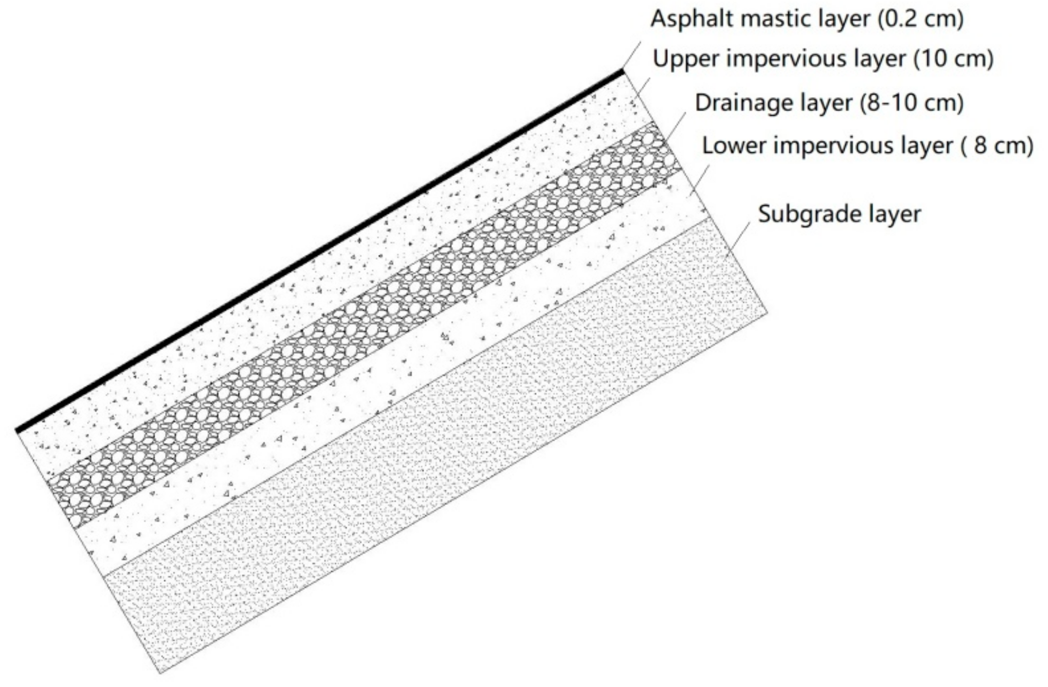
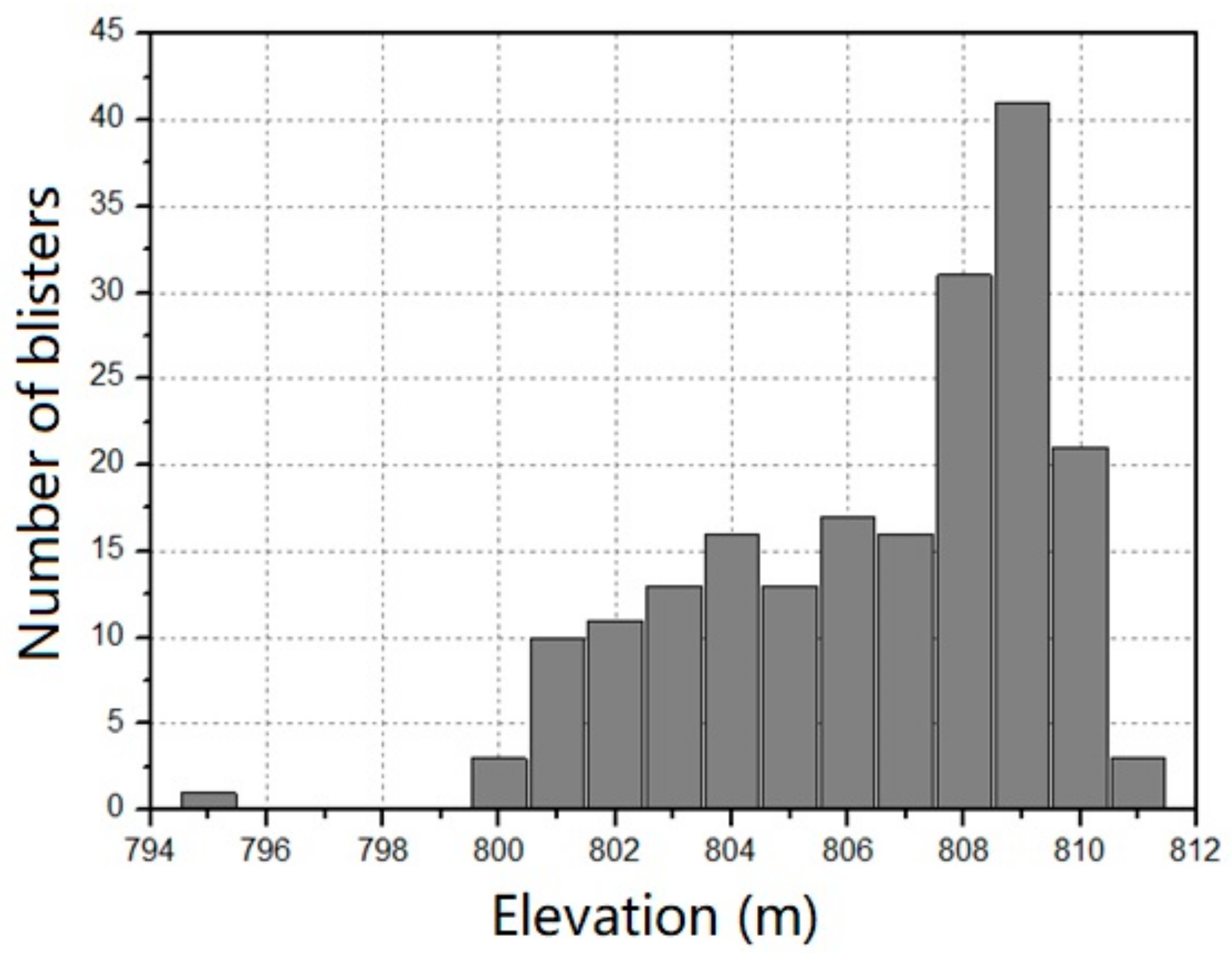
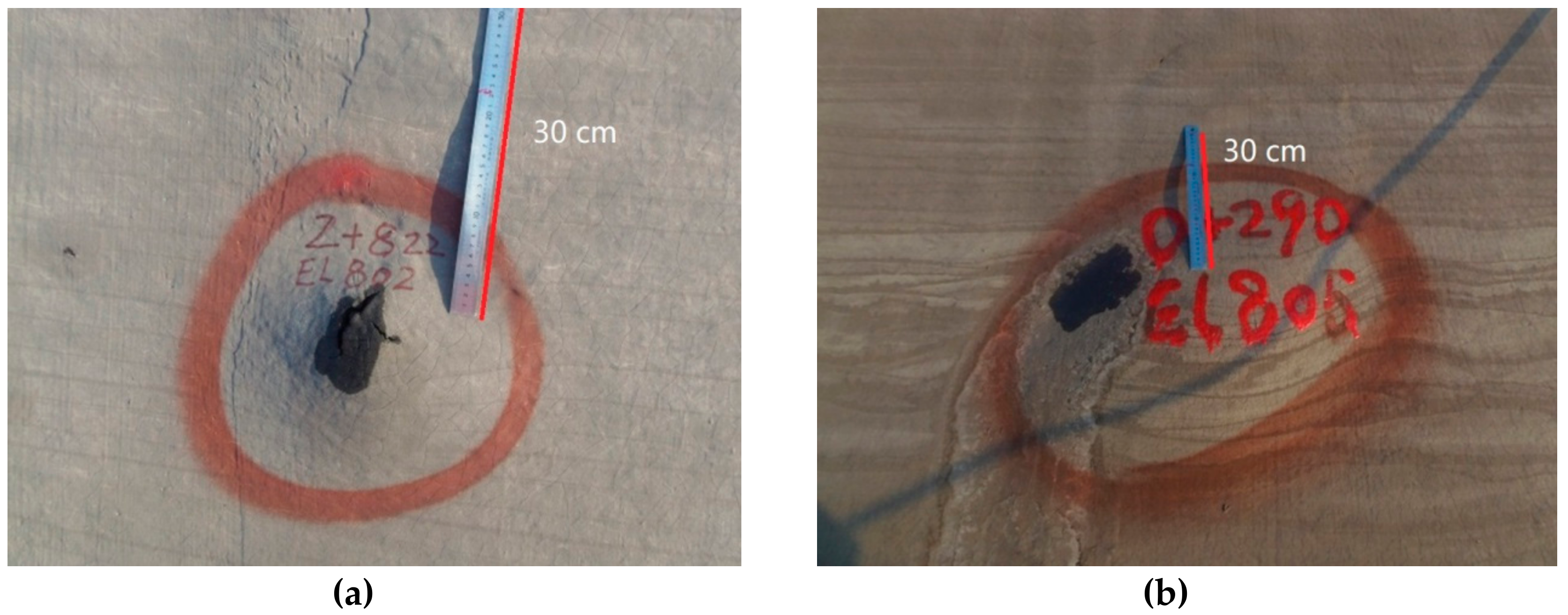
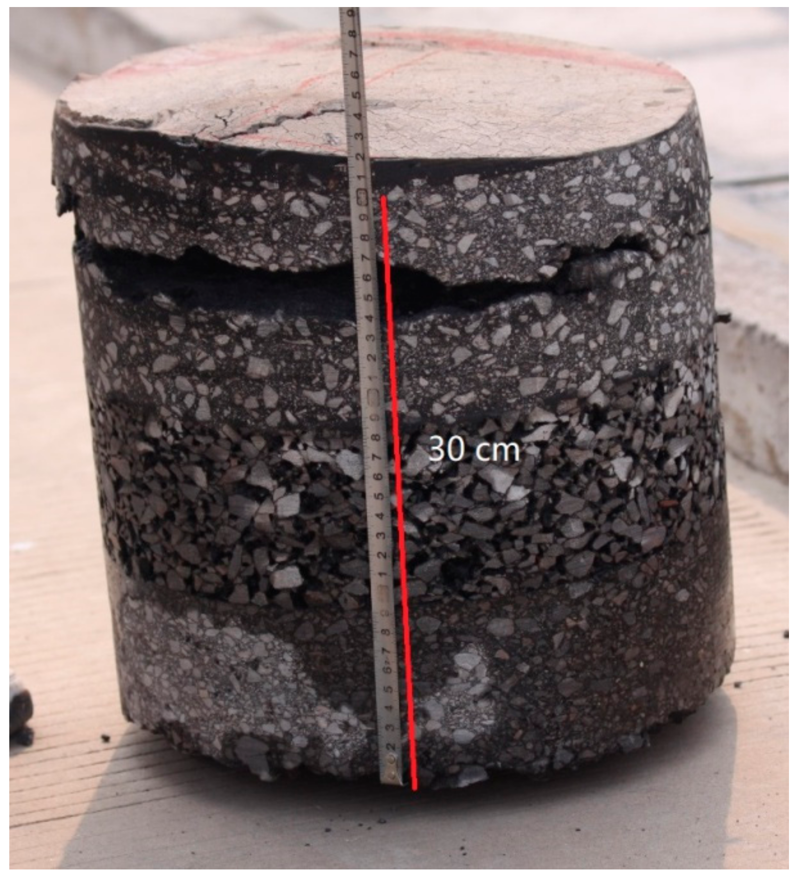
3. Blister Defect Characteristics of Zhanghewan Asphalt Concrete Facing

In April 2016, a comprehensive survey of the Zhanghewan asphalt concrete facing was conducted. A total of 282 defects were found, including 193 blisters, 87 local small-scale flows, a 40 cm long horizontal crack, and a blister on the sealing layer. The blisters were distributed between EL. 795 m and EL. 811 m, which was more or less consistent with the zone of the water level fluctuations; for example, the number of blisters from EL. 808 m to EL. 809 m was 41 (shown in Figure 2), indicating that blistering was related to exposure. In terms of size, blisters with diameters between 10 cm and 30 cm accounted for 78%, and those with a diameter of 10 cm were the most common with about 42 (shown in Figure 3). Blister size was substantially evenly distributed along the elevations. In terms of appearance, half of the blisters were cracked at the surface and half were not (shown in Figure 4).
A Φ30 cm core was drilled from a Φ40 cm blister at station number 0 + 325, EL. 801 m; the blister was cracked at surface. When drilling to about 5 cm deep, pressure water poured out, and the upper impervious layer of the core was found to separate into two layers at a depth of about 4–5 cm, as shown in Figure 5; the lower part of the upper impervious layer had no cracks or defects. This means there was enclosed water in the middle of the upper impervious layer, and the blister was likely to have been caused by the steam pressure of the water. Since the diameter of the blister was larger than the diameter of the core, the separation marks could still be seen on the inner wall of the drill hole.
In order to further inspect the blister, 9 Φ10 cm core samples were drilled in three typical areas, and the void content of the upper impervious layer of the core samples were tested. The void content and the permeability coefficient of the drainage layer were also tested and are listed in Table 2. It was found that all the core samples showed separation in the upper impervious layer, as shown in Figure 6. Geological radar test results also indicated that the blister defect was located in the upper impervious layer [14]. It can be seen from the test results that the void content and permeability coefficient of the drainage layer were moderate, the drainage layer was smooth, and no leakage water was seen in the drainage gallery, indicating that the moisture in the blister was less likely to have come from the drainage layer. At the same time, the void content of the impervious layer was less than 3%. As we know, when the void content of asphalt concrete is below 3%, the permeability coefficient will be less than 10−8 cm/s [15] and it is almost impermeable, which indicates that reservoir water is not likely to diffuse into the asphalt concrete. Therefore, the moisture in the blister was not likely to have come from reservoir water.
In addition, there were no problems of “sick” aggregate or impure aggregates in the asphalt concrete in the core samples. Therefore, according to these actual conditions, the moisture in the blister was more likely to have entered the impervious layer during the construction period. How the moisture in the impervious layer triggered the blisters currently seen requires further research.

4. Model Test of the Blister

Regarding the upheavals of asphalt facing, Sawada et al. conducted a model experiment to investigate the effects of water retained in the drainage layer and hydrostatic uplift on dam facing. It was concluded from the experiment that a water pressure as low as 0.06 kg/cm2 can cause the bulging of a 2.4 m × 2.4 m × 0.12 m asphalt slab at a temperature of 25 °C [16]. According to the coring of the Zhanghewan, there is water enclosed in the middle of the upper impervious layer. How this water formed steam pressure, and how large the value of the pressure was, were studied using the following model test.

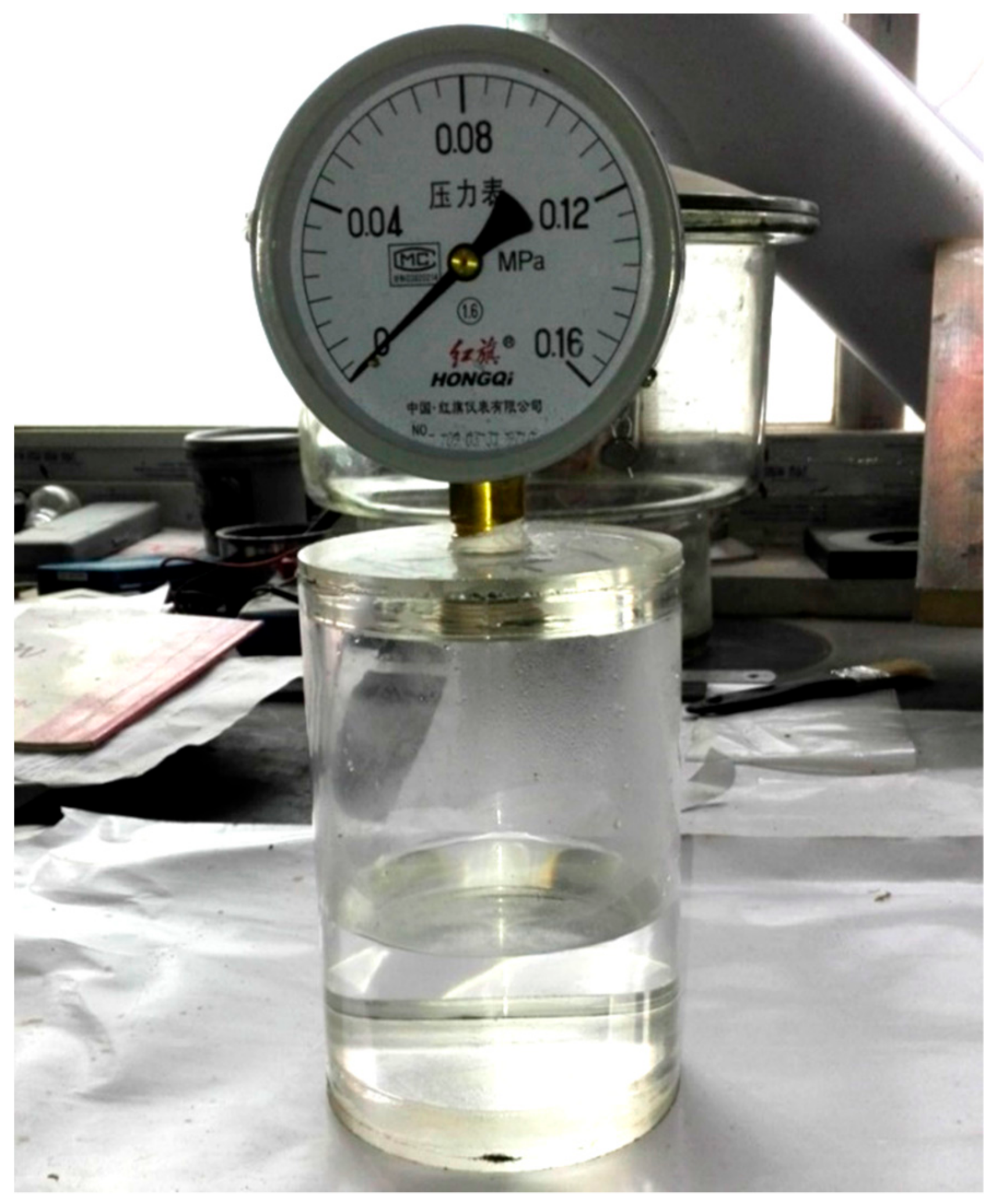
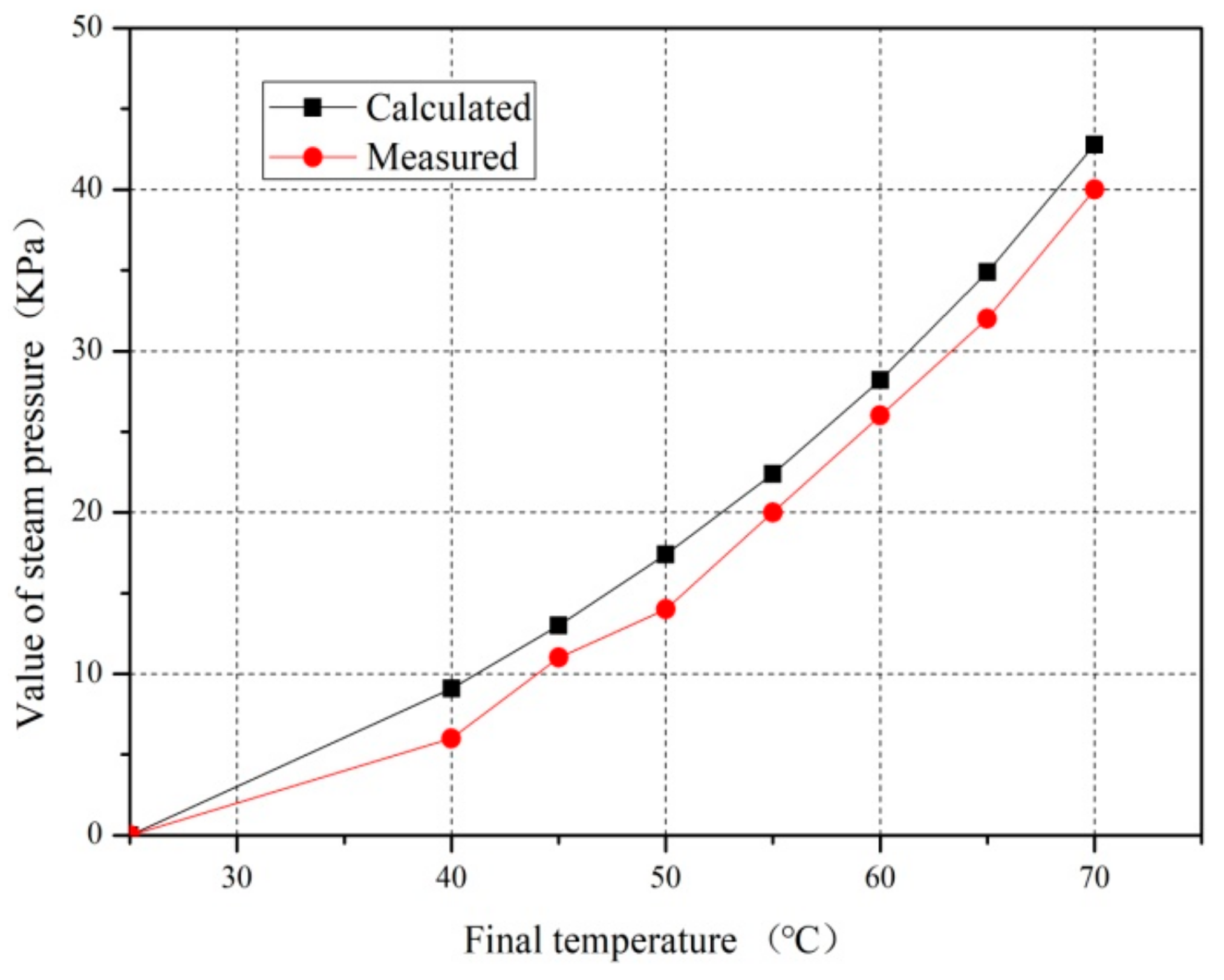
4.1. Estimation of Steam Pressure
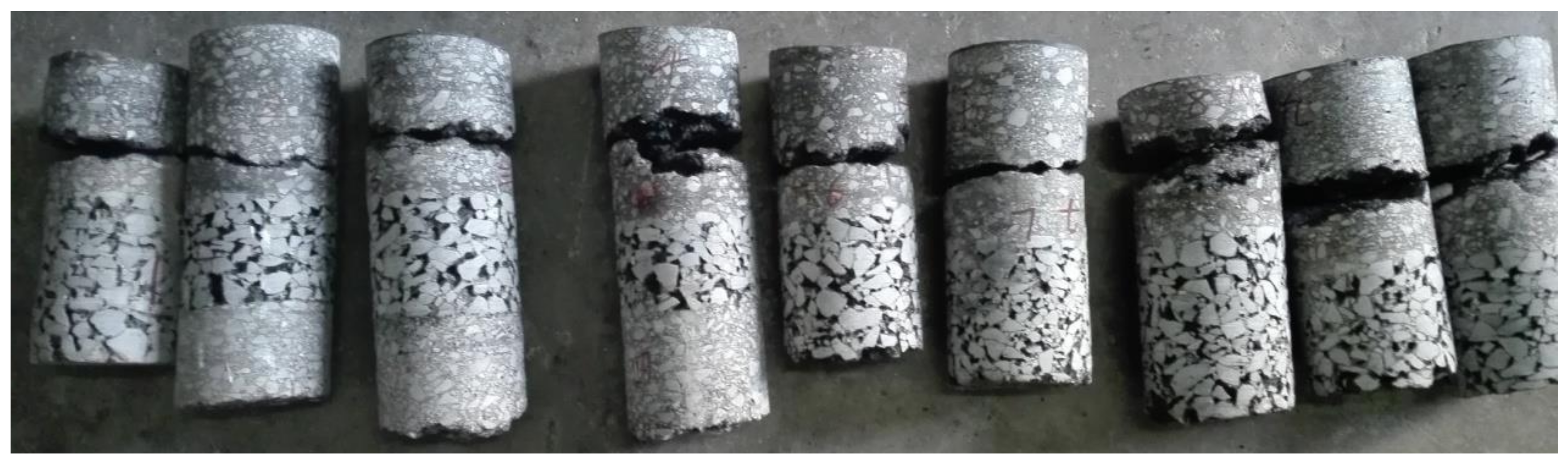
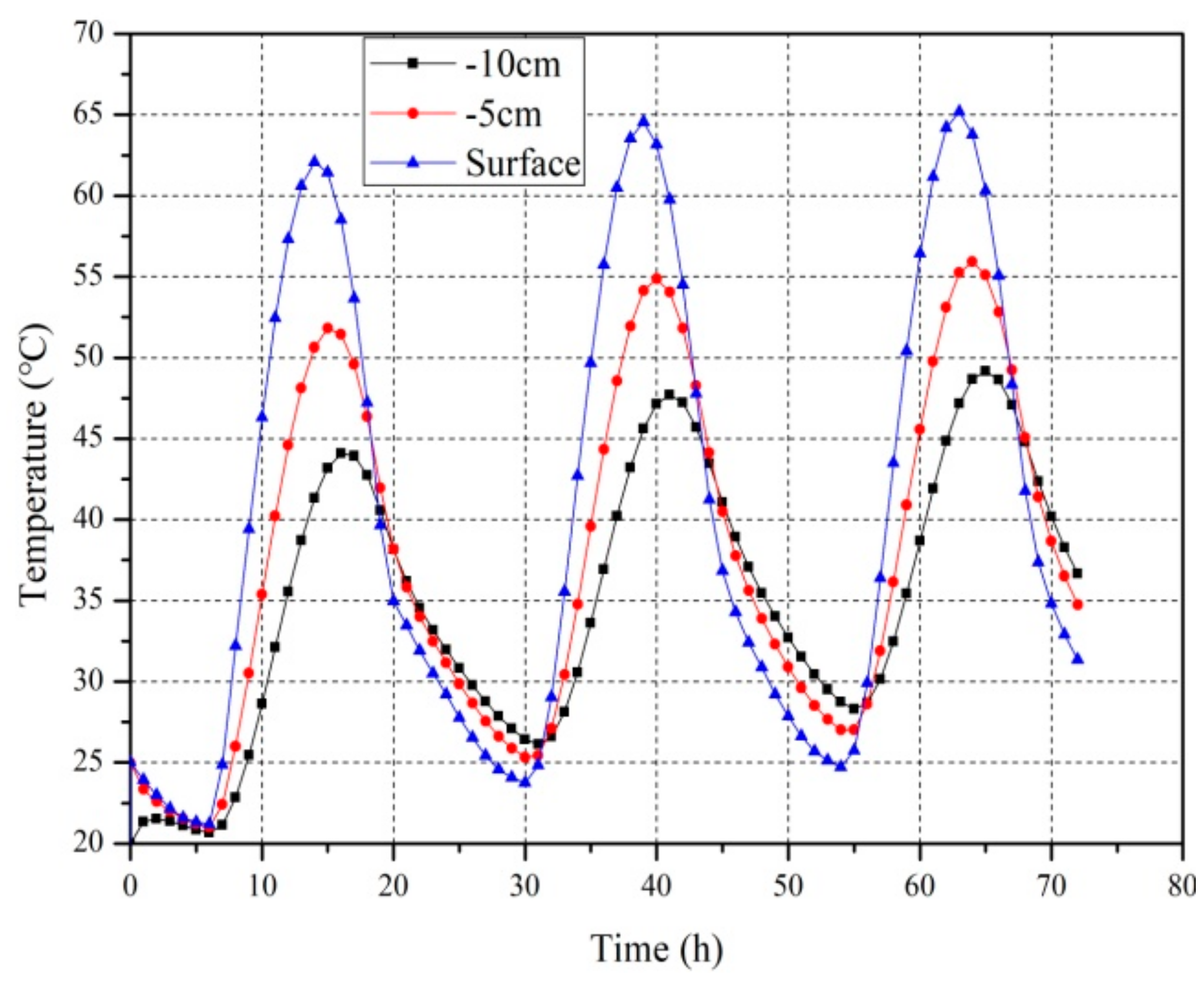
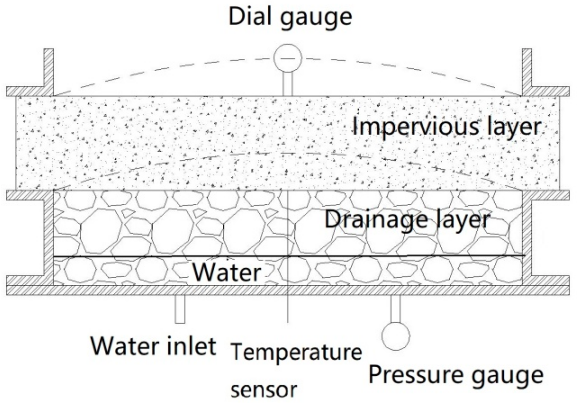
The asphalt concrete facing with water in the impervious layer can be approximated as a closed vessel with water. The pressure in the vessel is composed of two parts, one part is the saturated vapor pressure (Pw), and the other is the pressure of air (Pa). According to the Dalton’s law of partial pressure [17], the total pressure Pt of the mixed gas in the vessel is equal to the sum of the partial pressures of the components:
Pt = Pw+Pa.
Under a closed vacuum condition, the gasification of water, and the liquefaction of vapor will gradually reach equilibrium. The pressure at the two-phase equilibrium is called the saturated vapor pressure; the saturated vapor pressure, Pw, increases as the temperature, T, increases, and has no relation to the volume of the water. The saturated vapor pressure can be described by the following Antoine equation [18,19]:
logP w = A B T + C
where Pw is saturated vapor pressure, mmHg; T is Kelvin temperature, K; and A, B, C—are constants.
There are small differences in the values of A, B, and C in different papers; for example, in paper [20], for water of 0–60 °C, A = 8.1332, B = 1762.39, and C = 235.66.
It is assumed that the relationship between the air pressure Pa and the temperature T can be approximated by the following ideal gas state equation:
P a T = nR V
where Pa is the pressure of the gas, Pa; V is the volume of the gas, ml; n is the amount of substance of the gas, mol; R is the universal gas constant, 8.314 J·mol−1·K−1; and T is Kelvin temperature, K.
Assuming that the initial temperature of the vessel and water is T0, and the initial pressure in the vessel is an atmospheric pressure P0, according to Equation (2), the saturated vapor pressure is P w 0 = 10 A B T 0 + C , and according to Equation (1), the pressure of the gas in the vessel (Pa0) is P a 0 = P 0 10 A B T 0 + C .
When the temperature of the vessel changes to T, according to Equation (2), the saturated vapor pressure (Pw1) is P w 1 = 10 A B T 1 + C . According to Equation (3), the air pressure in the vessel (Pa1) is P a 0 = T T 0 ( P 0 10 A B T 0 + C ) . According to Equation (1), the total pressure in the vessel depends on the initial temperature T0, and the final temperature T as follows:
P t = T T 0 ( P 0 10 A B T 0 + C ) + 10 A B T + C .
In order to verify Equation (4), a test was carried out in laboratory. The test device was a 500 mL closed glass bottle with 50 mL of water inside. A pressure gauge was used to test the pressure inside the bottle, as seen in Figure 7. The initial temperature was selected as T0 = 25 °C, and the calculation results and test results are shown in Table 3. It can be seen that the measured pressure values are all less than the calculated pressure values, as shown in Figure 8, which may be related to the fact that air is not an ideal gas. In addition, if the numerical temperature is selected as T0 = 40 °C, the pressure gauge value of T = 70 °C can be calculated by Equation (4) to be 32.8 kPa, which indicates that the lower the initial temperature, the higher the pressure value at the same temperature.
The above analysis shows that the pressure value in the asphalt facing is related to the initial temperature. During actual construction, when the vibrating roller compaction water enters the impervious layer, the initial rolling temperature of the impervious layer can reach about 140 °C. However, the layer has not been compacted and closed, and the entering water is also in a state of intense phase change, with water vapor continuously leaking. The final temperature of the vibrating roller is also about 90 °C. The asphalt concrete has different permeability coefficients for water and water vapor, and the water vapor has a large permeability coefficient. Since water vapor may leak for a long time, it was assumed here that the initial temperature was related to the annual average temperature of the asphalt facing, and it is not necessary to consider the influence of temperature changes for many years. Determining the initial temperature of the water vapor pressure in the blister during the operation period is a complicated issue which needs further study. In the analysis below, the initial temperature was assumed to be 25 °C.
Equation (4) shows that the pressure in the blister is also related to the final temperature. Based on the aforementioned Zhanghewan blister sample, it is assumed that a certain amount of water is enclosed at a depth of 5 cm from the surface of the upper impervious layer, and the initial temperature is 25 °C. Since there is no measured data for the temperature, T, of the impervious layer, the numerical method is used for estimation. The three-dimensional heat conduction equation of a solid is of the following Equation (5). Since the asphalt concrete is not exothermic, Q is zero in the equation [21,22]:
T t = λ c ρ 2 T x 2 + 2 T y 2 + 2 T z 2 + Q c ρ
where T is temperature, °C; t is time, h; λ is thermal conductivity, J/m·h·°C; Q is internal heat source, kJ; c is the ratio of heat, kJ/kg·°C; and ρ is density, kg/cm3.
When asphalt concrete is in contact with air, there are two kinds of heat exchange modes: convection and radiation. The boundary conditions are shown in Equation (6) [23].
q = λ T n = β T Ta + ε σ T Tz 4 Ta Tz 4
where q is heat, J; T is temperature; β is the surface heat release coefficient, J/m2·h·K; ε is surface emissivity; σ is the Boltzmann constant, J/h·m2·K4; Ta is air temperature, °C; and Tz is absolute zero.
When there is heat flow (solar radiation) on the surface of asphalt concrete, the boundary conditions are as shown in Equation (7) [21]:
q = λ T n = α s f t
where f(t) is solar radiation, J, and αs is the solar radiation absorption rate.
The parameters such as density, specific heat, and thermal conductivity of the asphalt concrete thermal parameters used in the calculation are from the test values of Xilongchi [24] (as shown in Table 4). The surface exothermic coefficient, surface emissivity, and solar radiation absorption coefficient are from paper [21]. The Boltzmann constant is a fixed constant. Since there are no observation data on the temperature and solar radiation intensity at the site, the temperature curve, and solar radiation curve of a certain day in Shijiazhuang City (which is the nearest city to Zhanghewan) were used for calculation, as shown in Table 5 [25].
Using the above parameters, the temperature at depths of 5 cm and 10 cm below the surface, and at the surface of the asphalt concrete facing, was calculated using the finite element method (FEM), as shown in Figure 9. The effect of the asphalt facing orientation on the reception of solar radiation was not taken into account in the calculation. It can be seen from the calculation results that the temperature of the surface of the asphalt concrete facing could reach 60–70 °C under the action of high temperature and solar radiation for several days in summer. The temperature at 5 cm below the surface reached 50–55 °C, and the temperature at 10 cm below the surface c reached 45–50 °C. According to Table 2, the pressure would be 11–14 kPa and 14–20 kPa, respectively.
According to the above results (Figure 8 and Figure 9), for the asphalt facing containing closed water at 5 cm below the surface and an initial temperature of 25 °C, three temperatures of 45 °C, 50 °C, and 55 °C corresponding to 11 kPa, 14 kPa, and 20 kPa pressure were selected for the model test.

4.2. Model Test

In the test, an asphalt concrete slab was fixed on a steel cylinder model with an inner diameter of 500 mm. The steel cylinder was filled with drainage layer asphalt concrete, and the joint between the asphalt and the steel cylinder was sealed. Water was injected into the drainage layer and pressure was applied, in combination with the temperature selected in the previous section. The entire model was placed in an oven to observe the formation and variation of the blister.
The impervious layer and the drainage layer asphalt mixture required for this test were mixed in the laboratory. The asphalt mixture was mixed with Karamay 90 bitumen and limestone aggregate, and the mixing ratio was in accordance with the Zhanghewan project, as shown in Table 1. The asphalt mixture was molded at a temperature between 140 and 160 °C. First, the drainage layer asphalt concrete was formed in a steel cylinder of φ50 cm and a height of 10 cm. A temperature sensor was buried inside, and a certain amount of water was added into the drainage layer. Then, two kinds of impervious layer asphalt concrete, 10 cm and 5 cm thick, were formed thereon. The impervious layer asphalt concrete and the steel cylinder flange were bonded with epoxy resin, and the other side of the steel cylinder was sealed by a rubber gasket with a cover to ensure there was no air leak inside the entire model. The test model sketch is shown in Figure 10 and the model test results are shown in Table 6.
One of the differences between the model test and the site was that the drainage layer was used in the lower part of the model. This is because it was easy to add water into the drainage layer (the drainage layer has a void content of 16–20%), but it was difficult to add water into the model if we used two impervious layers. Since the deformation of asphalt concrete (blister size) is only related to the pressure value and the modulus of asphalt concrete, which is only related to temperature if the mix ratio is fixed, it was thought the results of the model test were still valid.
It can be seen from the test results that the deflection of the blister is related to the thickness of the slab and the temperature. The deflection of the blister is greater when the temperature is higher and the slab is thinner. For a 5 cm thick slab, when the ambient temperature is 55 °C and the corresponding water pressure is 20 kPa, the blister deflection span ratio is 0.116, and the blister is broken. These test results are more or less consistent with the blistering at the Zhanghewan project.
The above analysis and test results show that when there is a cavity with closed water in the impervious layer of the asphalt concrete facing, and the surface temperature reaches 65 °C in summer, the water in the cavity will generate vapor pressure due to vaporization, and the surface of the asphalt concrete may be blistered. The size and cracking of the blister is related to factors such as the size of the internal cavity, the outside air temperature, and the duration of the high temperature.

5. Conclusions

Through on-site observation and laboratory tests, the following conclusions can be drawn about the blister defects of Zhanghewan asphalt concrete slab:
(1) Blisters with a diameter was 5 ~100 cm, gradually appeared after two years of completion of the project, and new blisters are still appearing after ten years of operation. The blisters are distributed in the daily elevation range of the reservoir water level in the reservoir, indicating that blistering is related to the exposure of the asphalt facing.
(2) Through the core inspection and the ground penetrating radar test, it was found that although the blistering was mainly located in the upper impervious layer, there was no phenomenon whereby the entire upper impervious layer was blistered, indicating that the blistering was not caused by blocking of the drainage layer.
(3) The core inspection indicated that the air void content of the upper impervious layer was 2.47%~2.95%, i.e., less than 3%, which virtually eliminates the possibility that the water in the blister came from an external source (e.g., storage water, rainwater).
(4) When moisture entered and was enclosed in the upper impermeable layer, the analysis showed that under the ambient temperature conditions of Zhanghewan, the enclosed moisture generated a vapor pressure of 13–22 kPa (related to the initial temperature selection). The model test showed that for an internal cavity of 50 cm diameter (which is common in the Zhanghewan site), the saturated steam pressure could make the cavity form a blister. Furthermore, for a cavity with a diameter of 50 cm and a depth of 5 cm, when the temperature was 55 °C and the steam pressure was 20 kPa, the blister would rupture. These test results are consistent with the situation of the on-site blisters.
Based on the above analysis, it is estimated that the formation process of the blistering was as follows. The impervious layer was not fully pre-compacted after paving, and water entered when the vibrating roller was spraying water. The moisture was then sealed in the impervious layer after rolling, where many small water bodies were formed. After the reservoir commenced operation, these small water bodies continuously connected and grew under steam pressure, gradually forming blisters of different sizes according to the size and depth of the connected water bodies. In addition, there are virtually no blisters in the parts exposed above the water level. This is because these areas were artificially paved and no water spraying was used.

Author Contributions

Funding acquisition, J.H.; Conceptualization, J.H. and Z.W.; Methodology, Z.W.; Formal analysis, S.X.; Investigation, Z.S.; Data curation, X.L. and B.M.; Writing, Z.W.

Funding

This research was funded by the State Key Laboratory of Simulation and Regulation of Water Cycle in River Basin, grant number SM0112B242018, and by the China Institute of Water Resources and Hydropower Research (IWHR), grant numbers SM0145B442016 and SM0145B632017.

Acknowledgments

The authors would like to thank the anonymous reviewers for their constructive suggestions to improve the quality of the paper.

Conflicts of Interest

The authors declare no conflicts of interest.

References

  1. Jutao, H.; Cao, P.Y.; Liu, Z.H.; Wang, Z.X. Developingof a SBS polymer modified bitumen to avoid low temperature cracks in the asphalt facing of a reservoir in a harsh climate region. Constr. Build. Mater. 2017, 150, 105–113. [Google Scholar]
  2. Xia, S.F.; Lu, Y.H.; Wang, Z.X.; Zhang, F.C. Studies on the key technical problems ofasphalt concrete facing slabs in upper reservoir of Huhhot Pump Storage. In Proceedings of the 4th International Conference on Concrete Repair, Rehabilitation and Retrofitting, Leipzig, Germany, 17 September 2015; pp. 540–545. [Google Scholar]
  3. Wang, Z.; Hao, J.; Yang, J.; Cao, Y.; Li, X.; Liu, S. Experimental Study on Hydraulic Fracturing of High Asphalt Concrete Core Rock-Fill Dam. Appl. Sci. 2019, 9, 2285. [Google Scholar] [CrossRef]
  4. Embankment dams with bituminous concrete facing. In Proceedings of the Review and recommendations, Bulletin 114, ICOLD, Paris, France, 6 June 1999; p. 79.
  5. Peter, T. Long time behavior of asphalt concrete lined reservoirs and dams and their foundation. In Proceedings of the 1st International Conference on Long Time Effects and Seepage Behavior of Dams, Nanjing, China, 2 June 2008. [Google Scholar]
  6. Teltayev, B.B.; Rossi, O.C.; Izmailova, G.G.; Amirbayev, E.D. Effect of Freeze-Thaw Cycles on Mechanical Characteristics of Bitumens and Stone Mastic Asphalts. Appl. Sci. 2019, 9, 458. [Google Scholar] [CrossRef]
  7. Özgan, E. Modelling the Stability of Asphalt Concrete with Fuzzy Logic and Statistical Methods for Various Freezing and Thawing Cycles. Math. Comput. Appl. 2010, 15, 176–186. [Google Scholar] [CrossRef] [Green Version]
  8. Yang, Q.M.; Sun, Z.T.; Ding, P.R. Asphalt concrete facing for rockfill dams built by directional blasting. In Proceedings of the ICOLD 16th Congress, San Francisco, CA, USA, 4–5 October 1988; pp. 1091–1103. [Google Scholar]
  9. Szling, Z.; Szymański, A. The origin of and prevention from damage to impervious facings. In Proceedings of the ICOLD 17th Congress, Vienna, Austria, 14–17 October 1991; pp. 95–102. [Google Scholar]
  10. Garcia-Gil, L.; Miró, R.; Pérez-Jiménez, F.E. Evaluating the Role of Aggregate Gradation on Cracking Performance of Asphalt Concrete for Thin Overlays. Appl. Sci. 2019, 9, 628. [Google Scholar] [CrossRef]
  11. Kong, D.; Chen, M.; Xie, J.; Zhao, M.; Yang, C. Geometric Characteristics of BOF Slag Coarse Aggregate and its Influence on Asphalt Concrete. Materials 2019, 12, 741. [Google Scholar] [CrossRef] [PubMed]
  12. Frohnauer, R. Special application of asphaltic concrete for dam water barrier construction. In Proceedings of the Waterpower Conference 1999, Las Vegas, NV, USA, 6–9 July 1999; pp. 1–10. [Google Scholar]
  13. Schönian, E. The Shell Bitumen Hydraulic Engineering Handbook; Shell International Petroleum Company Ltd.: The Hague, The Netherlands, 1999; p. 449. [Google Scholar]
  14. Li, X.L.; Hao, J.T.; Wang, Z.X. Experimental study on ground penetrating radar in quality inspection of asphalt concrete impervious facing of pumped storage power station. In IOP Conf. Series: Materials Science and Engineering; IOP Publishing: Bristol, UK, 2018; Volume 423, p. 012020. [Google Scholar]
  15. Mallick, R.B.; Allen, C.J.L.; Teto, M.R. An Evaluation of Factors Affecting Permeability of Superpave Designed Pavements. In National Center for Asphalt Technology; Auburn University: Auburn, AL, USA, 2003. [Google Scholar]
  16. Sawada, T.; Nakazima, Y.; Tanaka, T. Emperical research and practical design of rockfill dams with asphalt facing. In Proceedings of the ICOLD 11th Congress, Madrid, Spain, 2–4 October 1973; pp. 281–313. [Google Scholar]
  17. Robert, G. Mortimer. In Physical Chemistry, 3rd ed.; Elsevier Inc.: Amsterdam, The Netherlands, 2008. [Google Scholar]
  18. Ohe, S. A Prediction Method of Vapor Pressures by using boiling point data. Fluid Phase Equilibria 2019, in press. [Google Scholar] [CrossRef]
  19. Choe, G.; Kim, G.; Yoon, M.; Euichul, H.W.; Nam, J.S.; Nenad, N.G. Effect of moisture migration and water vapor pressure build-up with the heating rate on concrete spalling type. Cem. Concr. Res. 2019, 116, 1–10. [Google Scholar] [CrossRef]
  20. Dean, J.A. Lange’s Handbook of Chemistry, 2nd ed.; Science Press: Beijing, China, 2003. [Google Scholar]
  21. Chen, J.Q.; Wang, H.; Zhu, H.Z. Analytical approach for evaluating temperature field of thermal modified asphalt pavement and urban heat island effect. Appl. Therm. Eng. 2017, 113, 739–748. [Google Scholar] [CrossRef]
  22. Chen, J.Q.; Li, L.; Wang, H. Analytical prediction and field validation of transient temperature field in asphalt pavements. J. Cent. South Univ. 2015, 22, 4872–4881. [Google Scholar] [CrossRef]
  23. Teltayev, B.; Aitbayev, K. Modeling of Temperature Field in Flexible Pavement. Indian Geotech. J. 2015, 45, 371–377. [Google Scholar] [CrossRef]
  24. Wang, W.J. Calculation and Analysis Report on Temperature Field and Temperature Stress of Asphalt Concrete Anti-seepage Panel of Xilongchi Pumped Storage Power Station; Xi’an University of Technology: Xi’an, China, 2004. [Google Scholar]
  25. Lian, Z.W.; Wang, L. Analysis of two kinds of historical extreme high temperature genesis in Shijiazhuang in the summer of 2002. In Proceedings of the 2003 National Major Severe Weather Process Summary and Forecasting Technology Experience Seminar, Chongqing, China, 10 July 2003. [Google Scholar]
Figure 1. Cross section of Zhanghewan asphalt concrete facing.
Applsci 09 02903 g001
Figure 2. Blisters along the elevation distribution.
Applsci 09 02903 g002
Figure 3. Blister size distribution.
Applsci 09 02903 g003
Figure 4. Blister on the asphalt facing. (a) cracked at the face; (b) un-cracked.
Applsci 09 02903 g004
Figure 5. Core of the blister (Φ 30 cm).
Applsci 09 02903 g005
Figure 6. Core samples (the coarse part is the drainage layer).
Applsci 09 02903 g006
Figure 7. Test device for steam pressure.
Applsci 09 02903 g007
Figure 8. The calculated and tested pressure values.
Applsci 09 02903 g008
Figure 9. Asphalt concrete facing temperature calculation results.
Applsci 09 02903 g009
Figure 10. Model test sketch.
Applsci 09 02903 g010
Table 1. Asphalt concrete mix ratio of the Zhanghewan project.
Sheive SizePassing Rate (%)Bitumen Content
191613.29.54.752.361.180.60.30.150.075
Impervious layer10010010092.468.758.146.226.217.213.311.77.7
Drainage layer10098.248.232.816.412.010.68.15.84.03.03.5
Table 2. Test results of additional samples.
No.Station NumberElevation/mDiameter of Blister/cmDepth of Separation/cmDrainage LayerVoid Content of Impermeable Layer %
Void Content %Permeability Coefficient cm/s
11 + 713809.0302.7–5.820.40.1142.85
21 + 627810.0407.4–9.117.20.2062.90
32 + 356809.0306.1–8.917.30.0852.47
42 + 349806.5405.2–7.320.20.1372.89
52 + 390.5809.0405.3–7.616.00.2672.68
62 + 741809.0207.3–8.518.30.0982.75
72 + 769809.0402.2–3.319.40.1032.67
80 + 56806.5402.6–9.320.10.1152.95
90 + 127808.0303.1–4.520.50.2012.82
Table 3. The pressure value in the vessel (calculated and tested, initial temperature T0 = 25 °C).
Temperature (°C)Calculated Pressure (kPa)Measured Pressure (kPa)
Saturated Vapor Pressure PwAir Pressure PaPt-P0
253.198.200
407.3103.19.16
459.5104.813.011
5012.3106.417.414
5515.7108.122.420
6019.8109.728.226
6524.9111.434.932
7031.1113.042.840
Table 4. Thermal parameters used for the calculation [23,24]
C
J/(kg·K)
ρ
kg/cm3
λ
J/(m·h·K)
β
J/(m2·h·K)
εσ
J/(h·m2·K4)
αs
Impervious layer95824506059684000.812.041 × 10−40.9
Leveling layer77122505184----
Cushion layer69121004752----
Table 5. Temperature curve and solar radiation curve of a certain day in Shijiazhuang City [25]
Time (h)Temperature (°C)Solar Radiation (J/h·m2)Time (h)Temperature (°C)Solar Radiation (J/h·m2)
025.801234.44,680,000
124.701335.34,544,008
223.701435.64,143,934
323.101535.33,503,030
422.801634.72,658,543
523.101733.71,659,551
62401832.6564,111.7
725.41,659,5511931.50
827.22,658,5432030.30
929.23,503,0302129.20
1031.24,143,9342228.10
11334,544,0082326.90
Table 6. Model test results.
Thickness (cm)Temperature (°C)Pressure (kPa)Deflection (mm)Deflection Span RatioRemarks
10451130.006No cracking, no leakage
5014110.022No cracking, no leakage
5520280.056No cracking, no leakage
54511110.022No cracking, no leakage
5014220.044No cracking, no leakage
5520580.116Cracked, leakage

