1. Introduction
One of the biggest problems facing modern electric utilities is a requirement to offset increased demand using demand-side management and demand-response algorithms [
1] or optimize the supply [
2]. The aggregate load is increasing monotonically, and the structure of the grid is evolving to support distributed resources. The grid is already stressed supporting modern loads with switching power supplies, highly dynamic usage profiles, and the proliferation of consumer/personal electronics. These new stressors overlay the already complex configuration of large conventional loads such as air conditioning systems, electric motors and water heaters. The continuing deployments of mobile loads such as electric vehicles will create complex new peak load patterns that were not foreseen by grid architects. As a result, utilities are evaluating a broad range of approaches to offset the increase in demand and complexity of aggregate load profiles. These approaches range from changing customer behavior via Demand Side Management (DSM) [
3,
4,
5,
6] to large capital expenditures and new generation facilities [
7,
8]. Simultaneously, the growth in functionality of machine-learning techniques has created an intersection point which may provide benefits in the optimization of distributed systems. Current ML-enhanced applications range from tourist guidance [
9] to malware detection [
10] to cataract detection [
11], and similar approaches may provide substantial benefits in the energy market. In particular, ML approaches directed at implementation in embedded and/or “server-less” or “edge” computing systems [
12] make the combination of ML and applications such as voltage optimization a very fertile environment for exploration. Finally, ML approaches have been found useful for energy disaggregation algorithms that provide important insights for optimal demand response [
13].
1.1. Terminology
The area of “voltage optimization” and “volt/var optimization” is overloaded with seemingly conflicting terminology. For example, in [
14], several terms are used and defined in specific ways, whereas in other references (e.g., [
15,
16,
17] and others) some terms may be slightly redefined, used differently, or conflated. As a result, we specifically define here what we mean by “dynamic voltage optimization” (
) and the relationship of this approach to other, similar approaches, all of which use various methods to optimize the transfer of power from the distribution grid to the end-user.
As described succinctly in [
15] and codified in [
18], “[c]ontrolling voltage is a fundamental task of distribution networks”. In fact, this problem reduces to a multi-point blind estimation where the accuracy of the voltage supplied to arbitrary end-nodes must remain within a small tolerance of a target value, regardless of various disruptive influences. Since voltage generally decreases along feeder lines due to various factors including distance, load characteristics, and equipment conditions, the logical approach to resolving the blind estimation problem is to raise substation voltage to counteract aggregate “line drop”.]
Conservation Voltage Reduction (CVR), which may also be known as Conservation Voltage Regulation or Controlled Voltage Reduction [
14,
15,
16,
19,
20] is the longstanding and well-known practice of controlling distribution voltage levels in accordance with existing standards [
18]. Techniques associated with CVR have been explored in North America since the 1980s [
14]. A superset of CVR is often described as volt/var optimization (“VVO”) and focuses on a sort of coordinated, distributed power-factor optimization using controllable reactive sources (e.g., capacitor banks). These approaches modulate distribution grid voltage and/or grid-resident subsystems to effect the optimization process. The target of these implementations is to produce meter voltages to the “bottom half” of the ANSI recommendations (114–120 V) at the far-end of the feeder, rather than maintaining substation voltages which result in “top half” ANSI recommendations at the meter (120–126 V). An issue in all cases is the uniformity of voltage along the feeder or the “first/last customer” problem.
Distributed Voltage Optimization (“DVO”) appears in a few references (e.g., [
15]) as an alternative approach to endpoint correction which regulates voltage at the boundary between distribution grid and consumer by modulating local power factor. Some references describe end-to-end (substation-to-consumer) CVR in terms of “Line Drop Compensation” (LDC) whereas approaches which are not end-to-end (e.g., require in-grid compensating systems) in terms of “Voltage Spread Reduction” (VSR), which “flattens” the voltage profile along the feeder, providing more uniform delivered voltage.
Similar terminology is used in a broad review published by the US Dept. of Energy [
21]. In this review, the purpose of CVR is to reduce the voltage as low as possible during peak and non-peak times, whereas voltage optimization (“VO”) flattens the load curve and optimizes voltage to meet utility objectives (e.g., minimizing loss, optimizing reactive power losses, etc.). This study also refers to volt/var compensation (“VVC”) as the ability to control remote in-grid devices to achieve volt/var targets based on sensor inputs, which is similar to the “VVO” concepts of other references. In the aggregate, [
21] concurs that CVR depends on data from end-of-line sensors to control in-line regulators and other grid-resident devices. In the studies examined by [
21], the effectiveness of the optimization process differs based on type of energy service provider, with investor-owned and municipal utilities producing a roughly 2.5% voltage efficiency, and cooperative providers producing a 3.5% voltage efficiency.
According to seemingly normative reference material published by the National Electronic Manufacturers Association (NEMA) [
22], the concept of volt/var optimization (“VVO”) depends on real-time information and modeling to effect coordinated control of voltage and current fluctuations. This process depends on in-line voltage regulators, LTC transformers, and shunt capacitor banks whose interactions with the distribution grid occur via an established model, built based on circuit assumptions, and operated via long-term feedback loops. In other words, conventional VVO is not “dynamic” and does not adjust the distribution circuit to changing conditions because of the time-lag in implementation as well as the inaccuracies of the modeling approach. According to NEMA, CVR is a type of VVO which leverages a “flexible, AC transmission system” (FACTS) to flatten voltage profiles and reduce system demand by controlling the feeder and lowering the distribution line voltage. With this definition, the topic of concern here is “CVR”. Regardless, we define an alternative term to ensure clarity.
The terminology used here is “Dynamic Voltage Optimization” ( ) which refers to the process of modulating the feeder voltage at the substation as well as along the distribution circuit to provide optimal supply voltage at the customer’s endpoint. This concept is enabled by real-time, on-wire communication between control and monitor devices which may be deployed at various points in the distribution grid. Using this description, the term used herein is similar to a combination of terms, including “DVO” “CVR”, “LDC”, and “VSR” and “DVR” which are defined/used in the literature.
The objective of the discussion here is not to standardize terminology or present an architecture for voltage optimization which has not been previously explored. Rather, the objective is to describe the intersection between areas of technology which may have valuable implementation considerations in the ongoing efforts to optimize distribution grid efficiency.
1.2. Motivation
Reducing demand on electricity generation and distribution resources subject to the constraint of minimizing customer inconvenience is a well-known conundrum. One useful general approach to these competing requirements is the concept of Dynamic Voltage Optimization (
) [
17,
19]. Approaches such as CVR, LDC, VSR, and DVO which are similar to
have been proven useful in numerous field deployments and small-scale trials. Similarly, a form of
has been explored in other field trials [
17]. In short, by carefully controlling the voltage supplied to the distribution system, significant savings have been demonstrated, and 1:1 power savings [
23,
24] have been realized.
Although approaches similar to
have demonstrated clear potential, many pilot programs have experienced limited success due to absence of real-time feedback [
25,
26]. Without real-time feedback, such implementations typically introduce a safety margin on the lower end of the distribution voltage to ensure regulatory compliance, and to protect customers from under-voltage conditions.
Field trials of systems based on statistical modeling using incomplete data have produced favorable outcomes, such as pioneered by companies including DVI Grid Solutions (
https://dvigridsolutions.com). However, each of these approaches require some form of feedback from the power grid, and so suffer from incomplete or sparse data due to limited line issues, cost of deployment, and related complexities.
By implementing real-time feedback and leveraging deployed grid subsystems to report voltage levels, a real-time
system can be realized and savings can be maximized to any given ambient condition. Approaches have been suggested which may provide a partial solution [
27], but the inclusion of ML techniques in concert with the enhanced data-gathering approaches have not been clearly articulated. ML techniques have been shown to improve performance in various non-traditional applications such as network communication [
28,
29] where data collection can be ongoing, and the real-time leverage available via the volume of temporal data may exceed its utility for storage. As a result, the combination of ML techniques with an on-wire sensor system has the potential to create multiple disruptive application vectors in this space, including substantial promise in the implementation of
.
The following sections of this paper describe the background and functional definition of CVR along with a detailed discussion of the benefits of CVR implementations, as embodied in case studies from major service providers. In addition, the paper introduces a novel and enhanced architecture based on grid-resident sensors with in-band communication and ML-directed optimization.
These capabilities provide various aspects of “grid awareness”, and in addition to enabling
may provide enhancements to technical, functional, and business processes that extend beyond the
application [
30]. These improvements are described with appropriate operational justification and presented in the context of an ML-enhanced, on-wire sensor system for the distribution grid.
2. CVR Background
CVR is a closed-loop optimization of power offered versus power required. The process of maintaining the voltage supplied to loads on the distribution grid while minimizing the total power required for system operation has been described by many terms, including CVR, LDC, VSR, and DVO. Here, we use the generic form “CVR” or “DVO” to discuss legacy implementations and related approaches, and the modified form
to describe enhanced approaches. The elegance of a functional CVR implementation lies in the simplicity of Ohm’s Law: Reducing the voltage supplied reduces the power consumed. In contemporary CVR implementations, the difficulty lies in “closing the loop” between loads consuming power and the substations supplying power to the distribution grid. To provide operational boundaries on this process, most utilities and regulators follow ANSI C84.1 [
18], which dictates that the AC voltage delivered to each customer must be 120 VRMS +/−5%, or 114 to 126 VRMS. From the service provider’s perspective, an effective CVR implementation allows the reduction of power input without degrading service levels to customers, and provides a controllable approach to contemporary issues such as peak-shaving. From the customer’s perspective, an effective CVR implementation is completely transparent because power delivery is uninterrupted, and peak-shaving is implemented in a fair and dynamic fashion. Thus, a “good” CVR implementation reduces the cost of providing power, which is a benefit to the service provider, while maintaining service levels, which does not perturb or disrupt customer requirements. Many references describe this as “bottom half” (114–120 V) versus “top half” (120–126 V) performance. In the absence of CVR, utilities typically practice a form of “oversupply” or “top half” performance to ensure that the voltage provided to loads is higher than the lowest allowable voltage.
To evaluate the operational impact of an effective CVR implementation, two complementary perspectives or “use cases” must be considered. The first use-case involves the activation of CVR as a system-wide conservation mechanism. The second use-case involves the activation of CVR as a method for Demand Response (DR), or peak shaving with rapid response times. The primary difference between these two use-cases is the segment of time where the CVR implementation is “active”. In the case of conservation, the CVR implementation is constantly active and adjusting the Actual Supplied Voltage (ASV) to achieve dynamic reduction in system losses. In the case of peak shaving, the CVR implementation is only activated at times when the peak demand is experienced, and CVR is used to reduce power for short periods of time. When CVR is employed as a system-wide conservation mechanism, the service provider dynamically manages all ASV values to a point just above the minimum acceptable level, or Minimum Supply Voltage (MSV), resulting in overall power reduction. The calculations are simple and can be expressed as a net savings in energy and a resulting benefit in generation capacity, or
where
is the percentage of total energy savings, expressed as a function of the CVR factor (
) and the percentage reduction in supply voltage (
) [
25].
When CVR is employed as a peak-shaving mechanism, it is only active when the service provider is experiencing peak demand. In this case, CVR is used to reduce power for a short period of time in order to maintain system stability. This use of CVR as a peak-shaving mechanism is effective due to the presence thermostatically controlled loads such as electric dryers, water heaters, and electric baseboard heaters. Assuming that the network has
N thermostatic loads that are opted-in for a demand response program then CVR for peak shaving usually has the form:
where
B is the maximum load threshold,
is the power demand from the thermostatic loads and
is the total power demand. For this class of loads, a short-term reduction in supply voltage reduces the instantaneous power consumed in exchange for an increased duty cycle. The benefits of CVR as a power management technique for these loads declines over a longer period of time (several hours) as they run longer to compensate for the lower supplied power.
3. Case Studies and Issues for Conventional CVR
The concept of CVR began in the mid-1900’s with the development of regulations, designs and application guidelines [
16]. Utilities stopped this practice in the 1960s. In the 1970s the California PUC required CVR to conserve energy [
16]. Research into the implementation and effectiveness of CVR is ongoing, and implementations are numerous. Most CVR research indicates that there is a 1:1 correspondence between reduction in supply voltage and savings in system power. In other words, for every 1% of voltage reduction a 1% savings in power is achieved. Most research also shows that for every 1% of voltage reduction 3% or more of reactive power reduction was also achieved. This is important because in most cases, reactive power is wasted as a system inefficiency, and requires additional equipment for power factor correction. Thus, limiting reactive power loss via CVR may also reduce capital costs. Most CVR pilot projects have reported a CVR factor of 1.0, although a variety of estimates are also described [
24].
3.1. Case Studies: Non-Optimal Results
Many service providers have implemented CVR mechanisms since the 1970’s in order to study the effect of this system optimization. A few of these case studies are summarized in
Table 1 and discussed in following sections. In the CVR test cases and studies considered here, a non-optimal or non-existent feedback loop was used. The savings can be optimized using real-time feedback and machine-learning algorithms to improve system efficiency.
3.1.1. Snohomish County PUD (SCPUD)
SCPUD updated their entire distribution system for general improvements and to enable CVR. The improvements were made to 68 Substations with a total of 272 feeders and 290,000 customers. An overall energy savings of 53,856 MWh/yr (6.15 MW on avg.) were achieved. The average customer voltage reduction was 2.3% with a CVR factor of 0.7. A typical feeder has 1.61% energy Savings (198 MWh/yr). Distribution system losses were reduced by 11,226 MWh/yr and the average customer saved 1.32% (156 kWh/yr) [
24].
3.1.2. California Investor-Owned Utilities (IOUs)
In 1976 the California Public Utilities Commission (CPUC) mandated that California Investor- owned utilities (IOUs) limit delivery voltage to residential and commercial customers to the range of 114–120 volts, effectively reducing the voltage bandwidth by half. The utilities complied and, through the end of 1978 it was estimated that more than 1 billion kWh (1 Million MWhs) were conserved through this practice [
24].
3.1.3. Central Florida Electric Cooperative (CFEC)
CFEC implemented voltage reduction as its first measure to reduce peak demand and lower demand charges. By adjusting in-line voltage regulation, the 125 V nominal voltage at selected distribution transformers was reduced by 1.5–3%. As a result, CFEC reduced monthly peak demand rates by up to 20%. Tests on the first substation to implement this voltage reduction revealed a 0.5% reduction in load for every 1% reduction in voltage (CVR factor of 0.5) during the summer and 0.75% load reduction in the winter. CFEC voltage reduction may be greater during winter peaks due to the prevalence of resistive heating in the service territory [
19].
3.1.4. Clay Electric Cooperative (CEC)
CEC employed voltage reduction as a peak demand reduction tool on ten substations for over 10 years. Using this approach, CEC reduced its substation voltages from 126 V to under 124 V (1.7%) to avoid monthly peak demand charges, reporting a 1% load reduction per 1% voltage reduction, or a CVR factor of 1.0 [
24].
3.1.5. Jacksonville Electric Association (JEA)
JEA realized a significant decrease in load using voltage reduction in 2003. By implementing a 5% reduction in voltage, JEA reduced load by more than 65 MW from the peak of 3166 MW. JEA reported no customer complaints during this voltage reduction event, which allowed all customers to receive electric service and averted rolling blackouts during an unprecedented demand peak [
24].
3.1.6. Georgia Power (GP)
By reducing the voltage drop from the substation to the end of line customer meter, GP reduced transmission and distribution system losses and gained additional margin to implement voltage reduction to reduce peak demand. On most of its circuits, GP typically holds service voltage at 123 V from the substation through the end of a given feeder line, as opposed to previously operating its substations at 126 V. GP claims that the resulting efficiencies reduce peak load by 264 MW system-wide, saving
$4.6 million in avoided peak power purchases during implementation in the summers of 1999 and 2000 [
24].
3.2. Issues: Implementation Problems and Decision Frameworks
The benefits and complexities associated with CVR and other voltage optimization solutions are not lost on the technical community.
Although the utility of coordinating multiple control devices in the distribution grid can be shown to produce a flatter voltage profile, the benefit of CVR is described as being isolated to only a small number of feeders, or 80% of the benefit of CVR is reaped from 20% of the feeders used [
21]. Furthermore, even though the benefit of operating feeders in the “bottom half” of the allowable ANSI C84.1 voltage range is clear, relatively complicated architecture of real-world feeders can be quite problematic, requiring extensive system modeling and only effectively servicing a minority of available locations [
31]. In fact, in testing by Idaho Power, only 264 of 600 available feeders were suitable for CVR evaluation, and only 30 were chosen due to cost of implementation, complexity, and likelihood of success [
31].
As a result of these issues, in [
32] the authors propose a “decision framework” for assisting in the process of implementing a CVR solution. In addition to the noted issues in numerous previous deployments, including [
21,
31], the general consensus is that implementing a CVR solution is extremely difficult due to challenges with identifying load characteristics, complexities of validating model parameters via field measurements, and the problems associated with data gathering and analysis from a nonstationary platform. Regardless, the decision framework proposed in [
32] accounts for topology differences and peripheral system impact in order to assist in the selection of “low hanging fruit” for CVR deployments or trials. The framework compares candidate feeders in terms of observable, quantifiable characteristics including power transfer distribution factor (PTDF) and voltage sensitivity factor (VSF) [
32]. In developing their framework, the authors in [
32] provide a comprehensive summary of CVR methods and trials.
3.3. Summary
As described in the brief case studies contained here, it is clear that CVR and related approaches to voltage optimization are effective even when implemented non-optimally, addressing only a minority of feeders, and in the absence of a decision framework. The cases presented here vary by operational characteristics as well as use (conservation or peak reduction), but in all cases, significant saving was achieved and service degradation was avoided. Additionally, research activity related to CVR and similar approaches is active worldwide, from small-scale pilot studies using voltage regulators in the U.S. in 2010 [
33] to studies on the concept of an “active distribution grid” in China in 2016 [
34] and reactive power compensation schemes in Europe in 2017 [
35].
Regardless of the decision frameworks employed and/or the approaches taken to implement a voltage optimization solution, the percentage of addressable feeders remains very low due to construction and condition. Furthermore, as summarized succinctly in [
14], the “physics of the processes are very complicated” which results in several misunderstandings of the causes, effects, and outcomes. Additionally, due to highly variable distribution loads, the conservation factor (
) is neither constant nor linear, and widely held assumptions may be incorrect [
14]. As a result, the benefits of additional data collection on systems under test is necessary.
In each of these cases, the conclusions are similar: the connection between distribution efficiency and voltage optimization is direct, and the savings due to deployment of such approaches in the distribution grid is likely to outweigh the cost of deployment, particularly over time. However, direct monitoring of voltage levels in the distribution grid requires deployment of sensors, communication schemes to retrieve information in-band, and algorithms to process, interpret, and react to grid conditions. In contrast, the architecture proposed here, which leverages already-deployed “smart meters” to provide information to upstream systems for geospatial and schematic location refinement, can be leveraged alongside CVR systems to implement a richer form of .
4. In-Band Sensor Network Requirements
Equipment required to implement some form of CVR has already been deployed by many utilities. For instance, tap changers at substation transformers; voltage regulators and capacitor banks are commonly deployed infrastructure for a typical service provider. Leveraging this infrastructure, a form of statically configured CVR can be implemented with simple line studies and no additional equipment. However, this “blind” or “open loop” CVR is rarely effective due to uncertainty and high variability in the ASV, or the voltage actually supplied. A robust system requires a “closed loop” implementation with reliable, real-time feedback of endpoint voltages. Strategically placed sensors with an efficient, real-time communication path are crucial to ensuring that the supplied voltage is maintained within allowable limits at all times.
In contemporary CVR deployments, accurate, real-time telemetry of ASV levels at distributed service points is not possible or practical. Instead, static calculations of voltage loss or “line drop” for specific line types, loads, and distances are often used as estimates or guidelines for establishing the Minimum Supplied Voltage (MSV) to be used in CVR algorithms. The statically calculated MSV parameters suffer from significant drawbacks, including non-real-time updates due to static estimation, inaccuracy due to dynamic load variation, and complexity due to manual calculations. As a result of these difficulties, the efficacy and practicality of broad-scale CVR implementations is quite limited. Utilities are unable to control or trust DVO implementations, and so the economic value and conservation potential of this technology remain unachieved.
A compelling alternative to static or manually established MSV parameters involves the use of distributed sensors and a low-latency feedback loop between the supply points (at the loads) and the DVO algorithm or actuator (at the substation or inside the network). With this closed-loop architecture, a CVR implementation becomes a implementation, and can provide a return on equity (ROE) that correlates directly with the number of sensor points deployed in the distribution grid.
In many cases, the expense of telemetry systems and the overall system management has made deploying an effective system wide control feedback loop cost-prohibitive. Wireless solutions require ubiquitous deployment and still do not report schematic conditions that would allow for effective command and control. The management associated with wireless systems for is also a significant issue. A requirement for balancing multiple communications technologies across licensed and unlicensed spectrum causes consternation for utility executives and planners. The complexity of such systems leads to escalating costs of Operations and Maintenance (O&M).
In contrast, grid-resident communications use the existing infrastructure of the utility, allowing for schematic command and control at far lower costs, and creating a platform for additional applications such as automated metering infrastructure, demand management and fault isolation and resolution. The assurance of a single communication type that covers 100% of the service territory is highly appealing. The best practices for optimizing CVR and achieving require addressing the critical components and balancing their functionality and cost, as discussed in following sections.
4.1. Sensor Network
A critical factor in any deployment is the management of voltage at the end of the line, or in locations that have historically low voltage levels. Ubiquitous distribution of conventional sensors is not sufficient, however. Sensors in a robust implementation must be aware of their schematic location on the distribution grid in order to report the feeder, phase, and other important characteristics of their supply circuit. This “grid location awareness” aids in system optimization as the voltage range is managed for conservation.
4.2. Control Points
A second critical factor in
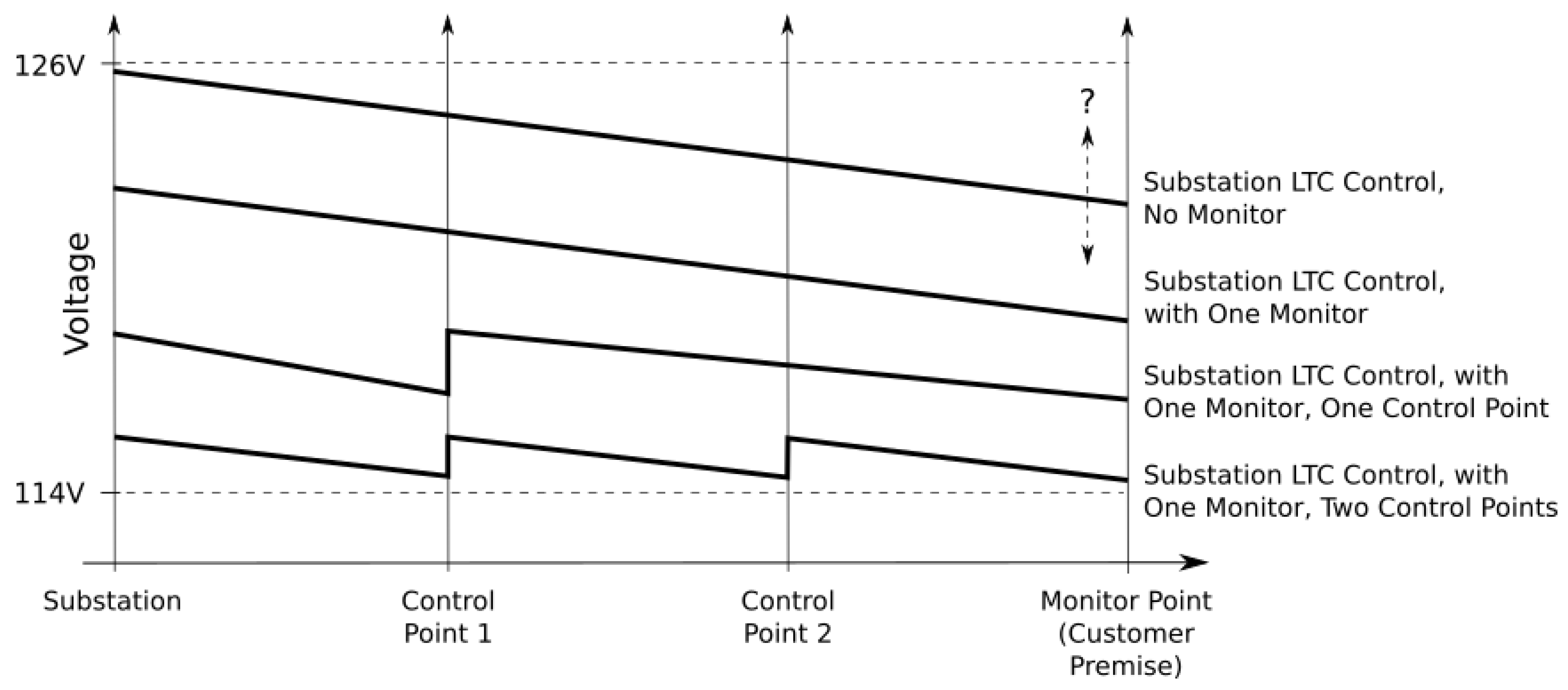
deployment is the establishment of control points along the line. These control points must be able to control voltage based on input from the sensor network. Control points can be deployed at the substation controlling the LTC (Load Tap Changer) as well as at voltage regulators, capacitor banks, or other control points anywhere along the line. The granularity of
voltage control is directly related to the number of control points deployed in the distribution grid. This is shown conceptually in
Figure 1. In the figure, the area under the curve decreases, and hence the
savings increases, as the number of control points deployed in the network is optimized.
4.3. Communications Channel
The final critical factor in deployment is the implementation of a reliable, real-time communication channel between system components. Reliable communications are critical to overall system effectiveness, and to savings realized through the use of . Intermittent communications certainly result in missed opportunities for power savings (inefficiency) and may also produce periodic supply voltage violations and brown outs in locations with highly variable load profiles. The deployment of a robust, grid-resident communication channel is the only way to assure reliable communications and synchronization between key components. In addition, a cost effective infrastructure deployment benefits greatly from sensors and communications that can support advanced applications, which complement and extend system capabilities beyond . Savings from as a standalone application are significant. Adding other applications such as AMR/AMI, Fault Isolation, Grid Mapping, and EV management enhance the value in a complete smart grid deployment.
4.4. Summary
In-circuit measurement and control, enabled by on-wire communication technology and real-time feedback works. In a recent substantial study, using in-circuit measurements and “reverse path” on-wire communications demonstrated that localized
can produce results which exceed the nominal 3–6% improvements [
36]. The remaining questions regarding this approach to voltage optimization revolve around “cost of deployment” and ancillary applications which can be leveraged to produce a more effective return on investment and logical business case.
5. Byproducts and Challenges
As has been discussed in the literature [
27,
37,
38] and demonstrated by trials [
36], an effective in-band sensor and communication network may be an important component of a fully functional
implementation. However, as also presented in the literature [
37,
39], this approach has a number of critical challenges remaining. In both the “byproduct” and the “challenge” issues associated with the in-band sensor concept, important considerations and benefits have substantial merit.
5.1. Byproduct: Grid Mapping
In addition to assisting with a
implementation, the presence of a robust in-band sensor network enables a form of location or registration (“Mapping”) of devices which are resident on the electric power distribution network (the “Grid”). Thus, the effect of the process described here can be referred to as “Grid Mapping” [
30,
40].
The approach to this mapping process depends on the use of “current profiles”, or characteristic disturbances in electrical current which are generated by grid-resident devices. When suitably processed, analyzed, and categorized, these current profiles can be detected at locations in the grid which may be distant from the location of the device which produced them. The presence of similar current profiles at different grid locations can be used to reveal the presence and approximate location of a grid-resident device or system. Thus, the process is “Grid Mapping” via “Current Profiles” [
40].
It is well-known that current disturbances persist in grid infrastructure. These disturbances have been used for applications related to fault detection and isolation, grid stabilization, and communications. It is also well-known that the location of grid-resident devices can be performed (inaccurately) via extrinsic methods such as GPS coordinates. The approach described in [
30,
40] performs approximate device location by correlation of downstream (specific) current profiles with upstream (aggregate) current profiles to determine the presence (or absence) of the downstream profile in the aggregated upstream location (typically the substation). In this fashion, important logistical information regarding downstream devices e.g., smart meters can be inferred from the collection of current profiles. This method provides a completely passive approach to “Grid Mapping”, where no information or excitation is added to the grid.
Time-synchronous information related to presence/absence of grid-resident devices is an important concept for Smart Grid infrastructure. Present grid implementations do not include device registration or location functions, and particularly not in a passive system architecture which requires no additional excitation. Accurate location of downstream grid-resident devices, including user devices (e.g., electric vehicles) and operator devices (e.g., transformers, smart meters, etc.) is an important aspect of all grid systems, and is a viable component of the Smart Grid.
Typically, the downstream, or specific, current profile (DCP) is observed from an electric meter or other endpoint device, whereas the upstream, or aggregate, current profile (UCP) is observed from a substation feeder or other infrastructure location. The downstream device (e.g., smart meter) may have nominal capabilities for data acquisition, processing, and storage and does not have access to “higher order” information which can be used in “mapping” or device registration. The upstream device may have significantly greater capabilities for processing, storage, data acquisition, and situational awareness of grid subsystems and architecture.
The DCP data is processed, encoded, and parameterized by the downstream device (e.g., smart meter) for efficient transmission to the upstream location(s), where it will be processed and analyzed. Processing at the upstream location(s) may include activities such as auto or cross-correlation involving DCP(s) and UCP(s) for the purpose of determining presence or absence of the DCP in time-synchronous UCP data as well as time-dependent notations for preservation of state and location information for each DCP. The techniques for data compression, the fidelity criteria, and the feeder-resident correlation operations for estimation of device presence/absence, along with processing for geo-spatial and network-architecture indicators are the subjects of ongoing ML-based analysis, which can provide the utility operator with numerous benefits related to situational awareness.
5.2. Challenge: Sidelobes
A major challenge in the deployment of in-band or on-wire sensor systems is the reactive nature of the distribution grid itself. Although some CVR deployments have noted the use of “reverse path” communications [
36], these same studies and related technical documents have noted difficulties with the channel characteristics. Conventional solutions and products which attempt “reverse path” communication are well-known, however only a few attempts have been made at resolving the “sidelobe problem” which perturbs and distorts such low-frequency communications. Here, we briefly describe some of the challenges and possible solutions previously described by the authors [
37,
39].
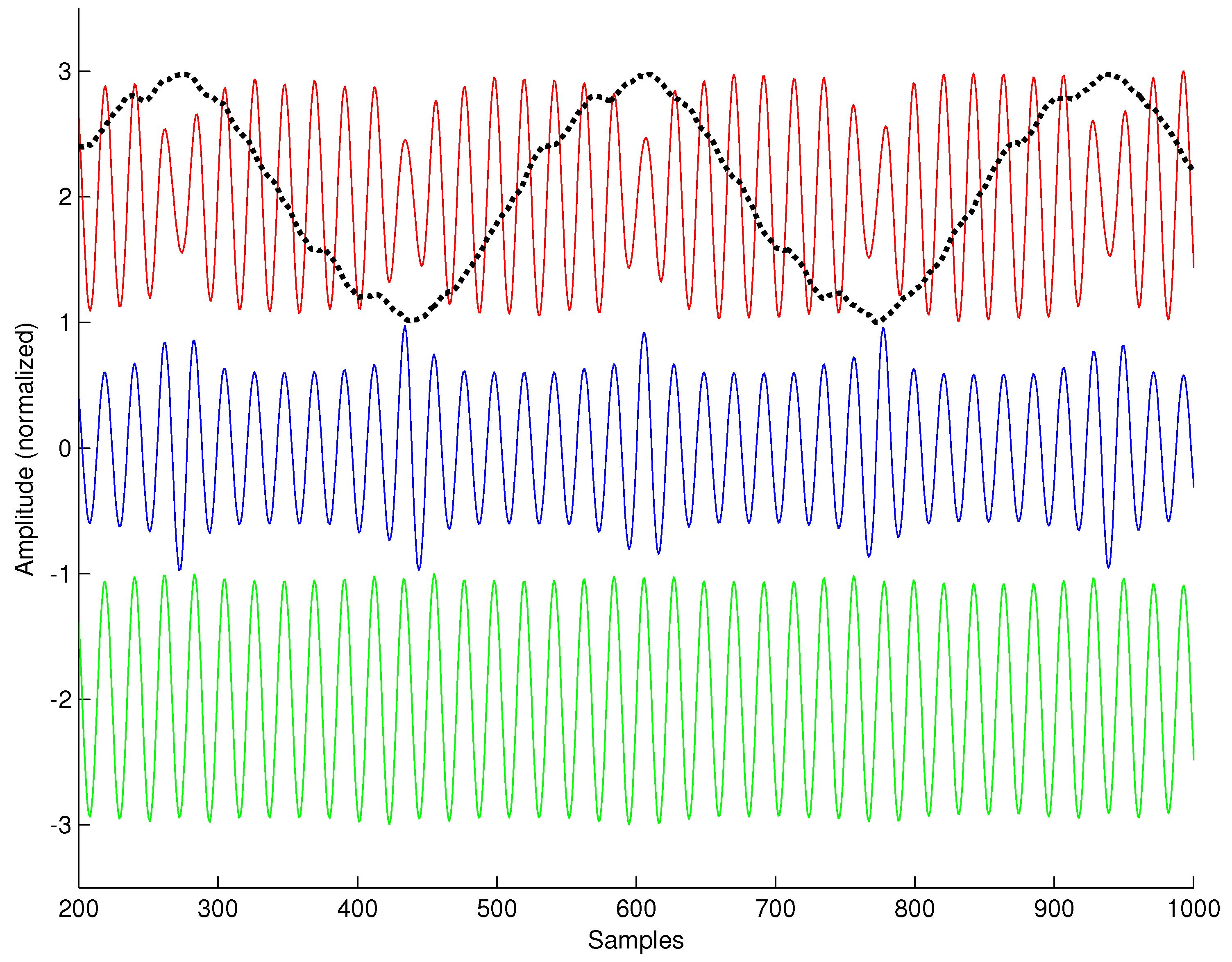
The distribution grid interacts with low-frequency communication signals to produce amplitude modulation which is coherent with the power signal itself. Predistortion of the communication signal prior to introduction to the channel has been shown to be effective in combatting these issues [
37]. An example of this phenomenon, as well as the coherent predistortion technique, is shown in
Figure 2. In
Figure 2, the distorted communication signal is shown in the top plot along with the normalized (synchronous) power signal,
. The middle plot shows the synchronously predistorted signal, and the bottom plot shows the in-channel result, where the channel-induced distortion on the communication signal is minimized. Minimizing channel-induced distortion in this case is critical because of the harmonically related images of the modulated spectrum, which can be disastrous for multi-carrier communication schemes.
The approach described in [
37] estimates a phase-coherent distortion envelope
from the power signal
and applies the inverse of this envelope to the communication signal. The envelope is constructed as a linear combination of functions of the fundamental, or
where coefficients
can be computed using any of several well-known techniques. This time-domain approach implicitly models the channel distortion with a very simple sampling technique, and does not require complex feedback loops or phase locking.
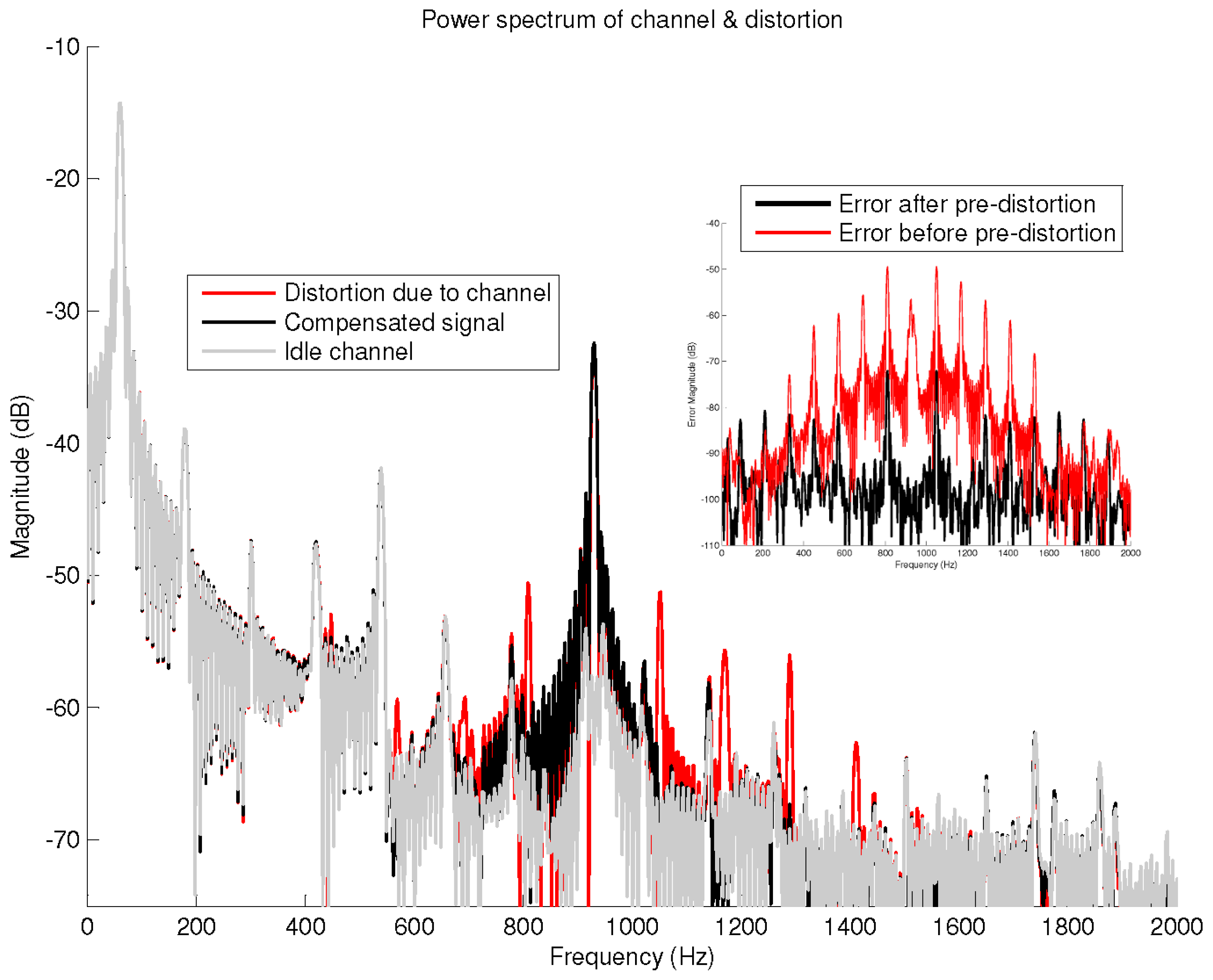
The utility of this predistortion is displayed clearly in
Figure 3 which overlays spectra of the idle channel, the channel with distorted input, and the compensated signal. The figure shows the distribution grid containing a low-rate communication signal with a carrier frequency near 900 Hz. When the pre-distortion scheme is not used, the images or sidelobes of the introduced signal are clearly evident in both figures at 120 Hz harmonic offsets from the carrier (i.e.,
). However, when the pre-distortion scheme is used, the images of
x are suppressed significantly. Additionally, the differential distortion between the original communication signal and the pre-distorted signal is less than 0.5 dB.
Estimation and inversion of the false message reduces to an optimization problem which depends on a linear combination of basis functions and the set of coefficients . Several well-known methods exist for optimizing coefficients of this form. Conventional optimization techniques have been explored, including Least Mean Squares (LMS), Recursive Least Squares (RLS), and so on. However, optimization of the coefficients for the linear combination structure of the predistortion function produce secondary optimization issues.
The suppression of image signals in low-frequency, narrowband PLC systems can be important. When optimized and deployed in a system which continuously re-optimizes the structure and outcome of the suppression envelope, the approach described in [
37,
39] may yield significant benefits. As noted in [
37], the optimal form of the pre-distortion problem is very difficult and the subject of considerable research effort. As a result, the use of ML methods for the structure of the predistortion function as well as the coefficients may be particularly useful in the very-low-frequency, constantly-on environment of the distribution grid.
In addition to valuable use in predistortion and other communication issues, ML methods may be particularly useful in the disambiguation of feeder and phase as well as localization of disturbances in geospatial and schematic contexts. ML techniques may result in the ability to rapidly decompose these disturbances or anomalies into a “feature set” which could easily be transferred upstream, retaining sufficient fidelity for locating the anomalies among the several feeders and phases that converge at a substation. By locating and categorizing these anomalies, and by assigning a probability of accuracy, the accuracy estimate would improve over time as more anomalies with better characteristics occurred on each phase/feeder.
The ability to map this in real time over a large area, leveraging geospatial data from smart meters as well as electrical information from the matching anomalies, could be quite valuable for distribution operators. As previously described, in most cases, geographic information systems (GIS) are unable to reconcile infrastructure requirements to schematic realities, particularly after a modification event (e.g., storm, phase balancing, etc.). As a result, the architecture proposed here is a form of large-scale “learning” that can be bootstrapped by several approaches, including a correlation receiver [
41] or equivalent at the upstream location as well as a recognition or decomposition system at the downstream location(s).
Subsequent sections of this paper describe conventional ML techniques and proposes the use of these techniques in the context of voltage optimization ( ) as well as disambiguation of distribution infrastructure via current disturbances.
6. Machine Learning in Voltage Optimization
Machine Learning (ML) is an application or science of algorithms that make sense of data in an age where data comes in abundance and turns the data into knowledge [
42]. The use of ML has expanded due to the amount of data is now being produced by applications, system implementations, and use of services. The use of ML approaches in voltage optimization scenarios could be a major contributor to the deployment and validation of “true”
.
Data comes in various formats and purposes to either an end-user or to a corporation to understand consumer’s preferences. To increase a level of knowledge of what the data represents and the time it was generated, it informs designers, engineers, scientist, stock-brokers, or doctors about patters, classifications, or predictions about the perspective data generator. There are three ways to develop a ML algorithm using data: supervised learning, unsupervised learning, and reinforcement learning. Each method presents a different approach in how the ML algorithm will learn its intended outcomes given a set of information to its input for evaluation.
6.1. Supervised Learning
Supervised Learning is the most common used ML method due the basic workflow to achieve learning at a high accuracy performance. Main goal of the supervised learning is to train the model with a set of inputs and known outcomes known as the training dataset. The model will then be validated and/or tested with another dataset with the input values only and check the outcomes with the desired outputs. Hyperparameters of the model can be adjusted to achieve higher accuracy levels as the design circles the training and test phases before implementation for its intended application. Classification and regression applications are common under the supervised learning method for ML algorithm models.
6.2. Unsupervised Learning
Unsupervised Learning is a method that does not require the labeling of the data or the target it needs to reach. Also, the unsupervised learning method does not require to obtain a feedback mechanism or know the structure of the data. This method enables the exploration of the data to extract meaningful information without the guidance of known outcomes or reward functions [
42]. One of the most common applications of unsupervised learning is clustering and dimension reduction. Clustering is a data science technique that help to organize data into sub-clusters depending in how the machine correlates data membership to categories of groups. This has shown in how data can be classified into unknown or unforeseen groups that exists in the data. Dimension reduction is a technique that receives data with high-dimensions or each data element contains several parameters and reduces the dimensions or number of parameters for each data element. This is also used for visualization purposes to “simplify” the number of dimensions that are display and not lose the interpretation of the overall data. A characteristic example of supervised and unsupervised learning is the clustering of energy data and energy usage analysis from a large dataset of smart meter data [
42].
6.3. Reinforcement Learning
Reinforcement Learning is a learning method focused on goal-directed learning from interactions to maximize a numerical reward signal [
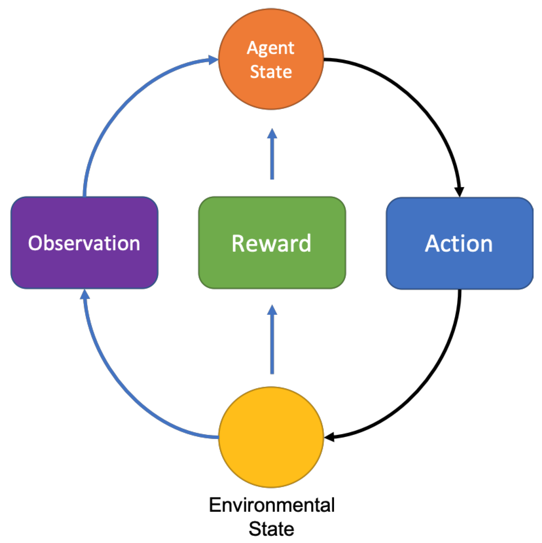
43]. Reinforcement learning is a method that acts as an agent that functions in a reward-punishment environment and learns by trial and error. Most of the reinforcement methods use a Markov Decision Processes (MDPs) that helps the model establish states through its trial and error learning-curve. The two main forms of reinforcement learning are by model-based and model-free approaches. The model-based methods rely on planning as their primary component, while model-free methods primarily rely on learning [
43]. Fundamental mechanisms of both methods of the reinforcement learning provide an action to the environmental state based on the current state that evaluates what was observed and the associated reward as seen in
Figure 4. A characteristic example of the implementation of reinforcement learning is for dynamic pricing [
44].
Table 2 shows a sample of the applications and models in ML classified within their own learning methods. Standard practice in finding the best fitting model is to apply the known data to different models that fit the desired application outcomes. The approach to apply ML to
is identify the key parameters for the model that can provide predicted outcomes at high accuracy levels without overfitting the model. An ideal ML model for
applications consist of evaluating inputs at a defined current state and predict the next state from previous knowledge of the network and information from the sensors.
6.4. Approaches Using ML in Real Time Systems
ML methods for real-time systems vary in the performance of the models and accuracy of the desired outcomes. For real-time systems, the supervised and reinforcement learning methods are more compatible to provide predictive outcomes as models can be trained in previous experiences. In the supervised learning method, the Recurrent Neural Network (RNN) and the Long Short-Term Memory (LSTM) models provide a time-series approach to predictions. For the reinforcement learning method, the Temporal-Difference (TD) prediction model and the Monte Carlo Tree Search (MCTS) model have been successful examples of decision-time planning and provide an ongoing process of learning optimal decisions that provide the highest rewards.
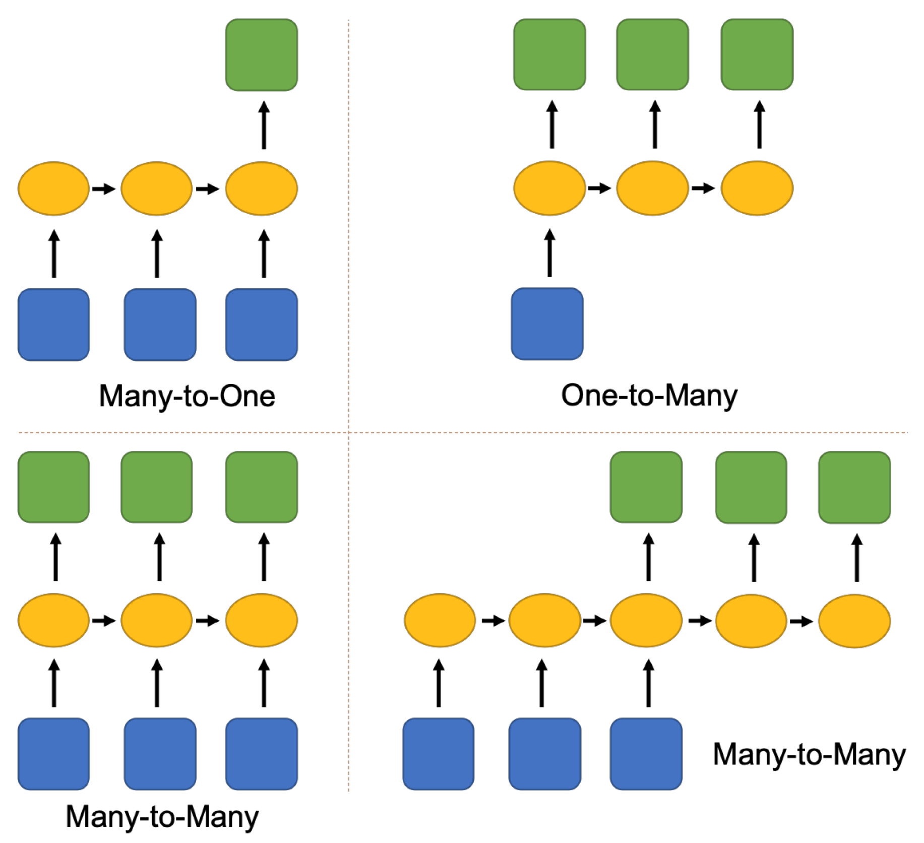
The RNN is a model that is trained by sequences of data, in where the order matters, and evaluates the desired outcome given the sequence presented at the input. This approach of time-series is a good implementation when patterns of a data are analyzed to form a conclusion of what was observed before in the sequence. The model can be trained to recognize certain patterns in the sequence of inputs, and the input layer can be extended to a large number of nodes to analyze longer sequences. However, if the RNN model requires to have a “good memory” remembering long sequences of values it will impact the performance of the model and computational resources if not running on high-end servers. There are three categories of sequence modeling with four configurations of the model as shown in
Figure 5: many-to-one, one-to-many, and many-to-many.
The LSTM model a recurrent network architecture in conjunction with an appropriate gradient-based learning algorithm designed to overcome these error back-flow and learn to bridge time intervals in excess of 1000 steps even in case of noisy, incompressible input sequences, without loss of short time lag capabilities [
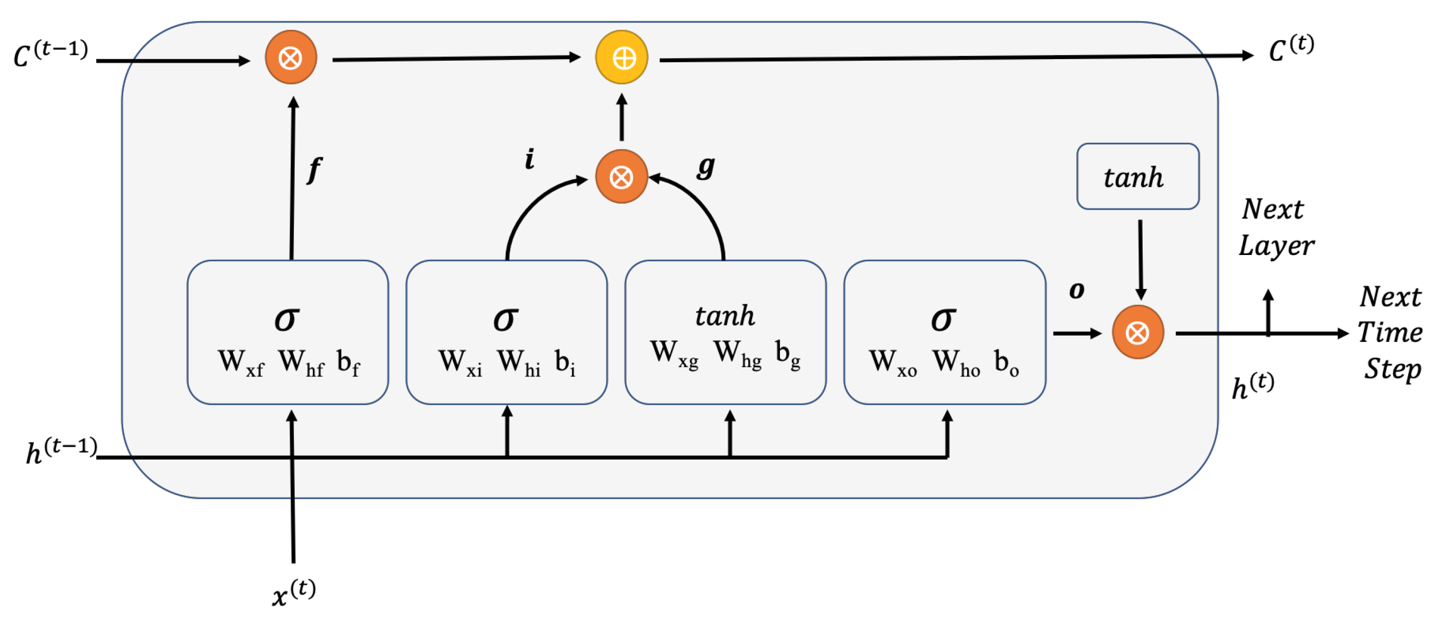
47]. The LSTM memory cell is design in three stages (gates) that provide a recurrent cell state while considering the previous states.
Figure 6 displays the design of a memory cell of an LSTM model. The memory cell has three gates combine the forget gate ( f) from the previous state, the input gate (i) in the current state, and the output gate (o) that provides the current state value and hand-off the next cell. LSTM is a popular implementation for detecting patterns in sequences of events to provide forecast values.
The reinforcement learning approach differs from supervised and unsupervised learning in the form of having the ability to have an ongoing learning process and provide an action. Due to this difference, it also takes a long time or a vast amount of data to accomplish the optimal training of the model. However, the benefits of the reinforced models are the capacity to handle more complex system operations, learn from mistake, and find the right decisions with greater rewards such as the Monte Carlo Tree Search (MCTS) and Temporal-Difference (TD) prediction models.
The MCTS model is an algorithm of decision-time planning with means of accumulating values estimates obtained from the Monte Carlo simulations in order to successively direct simulations toward more highly rewarding trajectories [
43]. MCTS is better known for the capability to learn the game Go, developed by the AlphaGo team from Google, and defeated the 18-time world Go champion. This model approach will require many examples to learn and understand what optimal choices are needed for desired decision. However, the MCTS has proven that with enough data and examples to learn from will find optimal actions to take and present to achieve high reward outcomes.
The TD model is model-free application approach that uses Monte Carlo simulations to estimate values and adjusts prediction with high accuracy before outcomes are known. TD models either have a tabular, denoted as TD(0), prediction approach or n-steps to use statistical bootstrapping. The advantage of TD models is that they do not require the model of the environment, of its reward and next-state probability distributions, and functioning in an incremental fashion. Also, TD methods have usually been found to converge faster than Monte Carlo methods on stochastic tasks [
43]. The convergence performance of the model is due to the form in which current and next states are determined by estimations using known true values of the current state and determine its next states.
7. Smart Deployments
A logical approach to deploying a Grid Location Aware system must use a best practice and continuous improvement methodology that allows for addressing current grid challenges as well as addressing the dynamic grid as it changes over time. As with any systems management challenge, all aspects of the solution must be considered including sensor placement, control point management, and system integration & management.
A well-designed
system should be simple and economical to deploy. Devices, which exhibit “grid location awareness” can be deployed and managed with minimal oversight. Communications should take place directly over the power lines with no requirement for off-grid secondary networks. The key to this simplicity is the ability to communicate on the wire over multiple transformations without repeaters or bypasses. Until recently, this communications ability was thought to be impossible [
27]. The result of this novel architecture is a complete end-to-end system of controllable nodes and sensor locations for total
optimization and quality energy delivery.
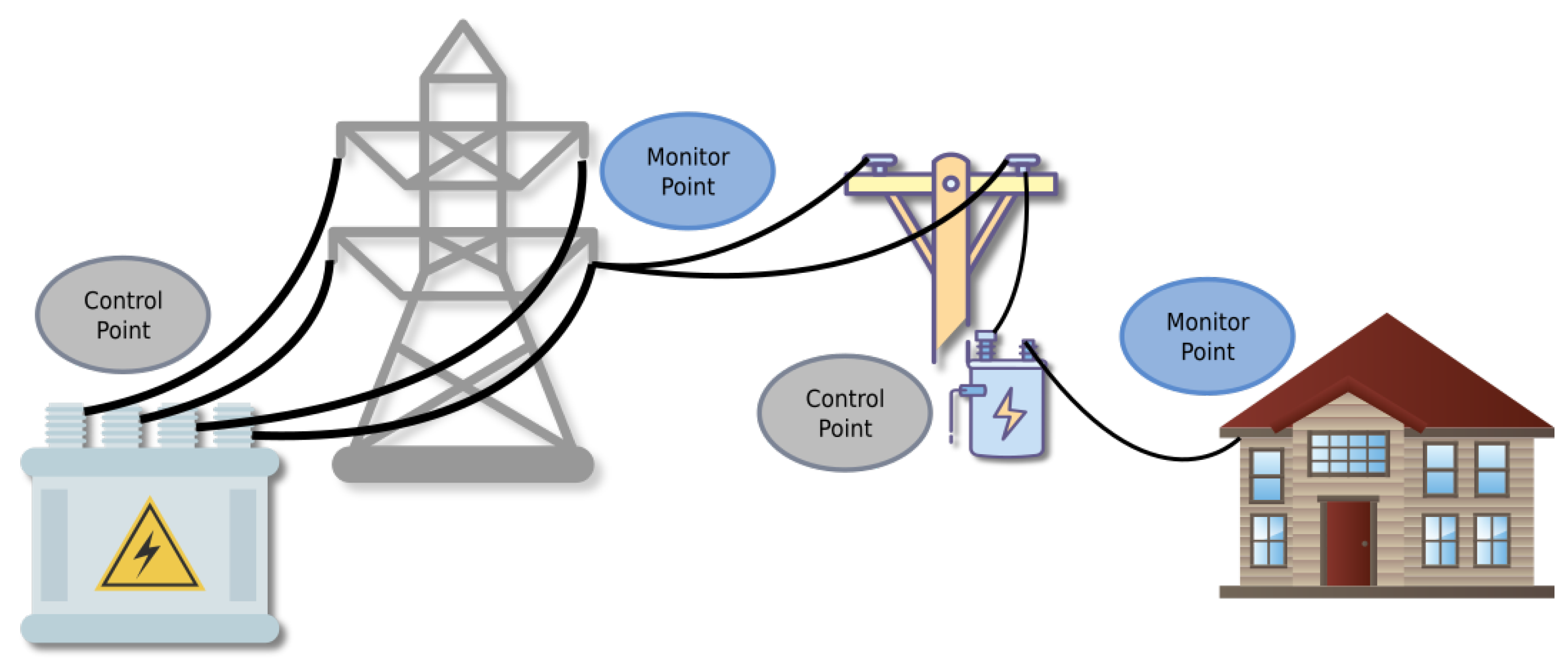
This system architecture is shown in
Figure 7. In the figure, the
monitor at the endpoint transmits the current system voltage along with other telemetry data to the substation and in-line equipment. The substation and the in-line equipment are programmed to adjust the system optimum voltage level based on data which provides complete “grid location awareness” at the device level.
monitors throughout the system help protect customers from low voltage conditions or brownouts, and feedback for exception conditions is instantaneous due to the in-line, on-grid communications paradigm.
Communications with mid-point grid devices provides additional value and resolution. Control of devices such as capacitor banks, regulators, tap-changing transformers, and switches based on real-time voltage feedback is an added benefit and can increase savings significantly. Key to any successful deployment is the careful measurement of the grid characteristics and the specific factors involved in managing including circuit length, load types (residential, commercial, industrial and agricultural), and substation architecture. Additionally, once an on-wire or grid-resident communication system is implemented, the concurrent leverage of ML-based optimization and ML-driven is also enabled.
The ideal ML model will have the capabilities to have an ongoing learning behavior from data coming from sensors and endpoints. The reinforcement learning method, such as the TD or MCTS, approach is the best form of implementation that can estimate the best rewarding predictions or actions and continues to learn from events. This provides the ML model ways to monitor the data, behavior of sensors, and provide a grid-wide optimal solution for distribution. It can learn from extreme events, abnormal events, and finding optimal operational functions to a granular level on individual sensors, endpoints, and control devices. The ML model would sit on a centralized computing server were all of the data telemetry is transmitted to and analyzed for evaluation, transmission, and action.
Another form of implementation is to establish an edge ML inference models in the sensors, endpoints, and to the mid-point grid devices dedicated for specific type of data and behavior. At the same time, the reinforced model will also monitor activities and learn from grid events as it tries to find the highest reward outcomes for the whole system. The benefit of this implementation is that the edge ML inference models can be different types of supervised-learning models such as the RNN and LSTM. Inference model execution is now broadly available such as Google’s Coral embedded AI solution [
49], and Nvidia’s Jetson Nano that supports AI frameworks like TensorFlow, PyTorch, Caffe, and MXNet are supported, and capable of running multiple neural networks in parallel to process data and drive action [
50]. Utilizing levels of smart
deployments at the edge and centralized will provide a robust ongoing analysis in real time and find optimal actions that lead to high reward predictions to the grid.
8. Prototype Implementation and Results
A prototype of the approach proposed in this manuscript may be useful in a limited-scope demonstration of its effectiveness. In the prototype implementation, the authors implemented data acquisition and processing technologies at a “downstream” location inside a live distribution network, as well as at an “upstream” location inside the substation servicing the distribution network. In each location, sensitive current transformers were used to detect current profiles, and data acquisition systems were employed to acquire time-series data of the current profiles.
At the downstream location, a series of current disturbances were manufactured using a real-time current modulation system. These waveforms were introduced directly into a conventional low-voltage outlet, captured with a data acquisition system, converted to a DCP data packet via limited ML analysis, and transmitted using an out-of-band network to a central location for comparison with UCP data captured at the servicing substation. Unfortunately, the distribution system servicing our prototype test environment was not equipped with an actual “smart meter.” As a result, we implemented a data acquisition system with localized processing and formatting immediately outside of the conventional meter which services our test environment. We refer to this as an “emulated smart meter.” The DCP data packet created by our emulated smart meter contained characteristic information of the current disturbances (anomalous characteristics) as well as geospatial information (location) and timing information (time-stamps). The primary objective of the DCP data packet was to create a “matching template” for further processing and comparison with high-resolution UCP data in order to prototype the DCP/UCP localization process.
At the upstream location, high-resolution data acquisition equipment was attached to the low-side of current transformers which are typically mounted on circuit breakers of high-voltage distribution feeders. The current sensing capabilities of the feeder circuit breakers are sufficient for acquiring DCP current anomalies which have transited the distribution network upstream from the low-voltage network to the substation bus-bar. This acquisition process creates UCP “data blobs” which contain waveforms of amperage for each phase of a three-phase feeder. In this fashion, UCP data is time-registered and normalized for comparison with DCP data packets using any of several signal processing and/or ML algorithms. In our test environment, our ML analysis was limited to various frequency and amplitude vectors characteristic of the manufactured disturbances, and the DCP/UCP comparison was accomplished via a correlation template.
8.1. Phase Disambiguation
One of the most fundamental operations associated with DCP/UCP comparison and registration is disambiguation of per-phase data. As current disturbances propagate through the distribution grid, towards the substation, the multi-phase nature of the distribution infrastructure provides fertile ground for cross-talk, as described in detail in
Section 5.2. Because of the nature of the distribution grid, even though anomalies will only occur in a single phase of the downstream network, versions of the anomalies will show up in all phases of the feeder where they occurred. The anomalies may have some combination of phase shifts and amplitude distortions, and often have other anomalies intertwined. This is mainly due to cross-talk in the core of the several transformers that are in the path. As a result, disambiguation of per-phase data via UCP profiles combined with geospatial registration associated with the out-of-band DCP profile can be of substantial value for the service provider. The correlation between phases and geospatial registration of a specific distribution phase with a specific meter (or set of meters) provides real-time situational awareness of the physical construction of the distribution infrastructure. As described previously, this “as modified” information can result in operational insights related to natural disasters as well as operational efficiencies related to phase balancing.
In testing of our prototype system, we achieved over 99% accuracy in phase disambiguation with current disturbances that were “large enough” at the emulated meter to remain detectable even after passing through several transformers en route to the substation feeder breakers. Research is ongoing to determine which dimensions of “detectability” are most important in this process as well as the operational parameters of each dimension.
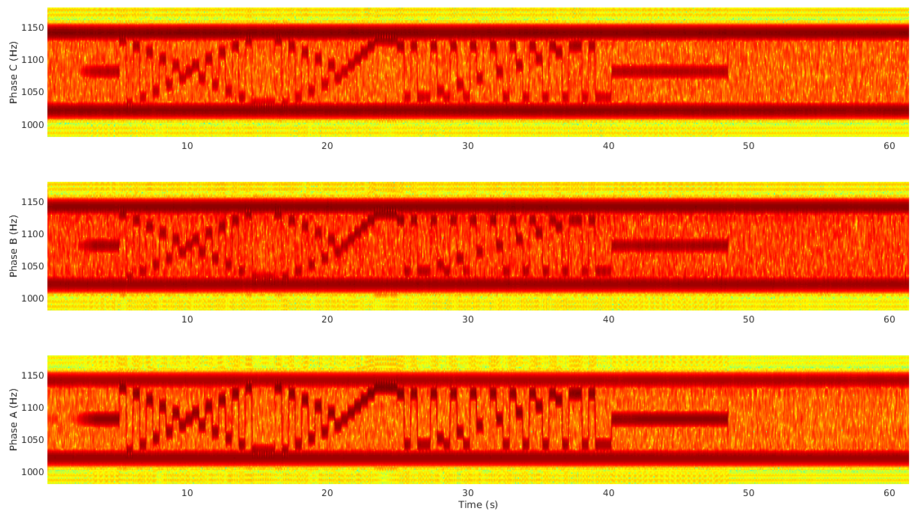
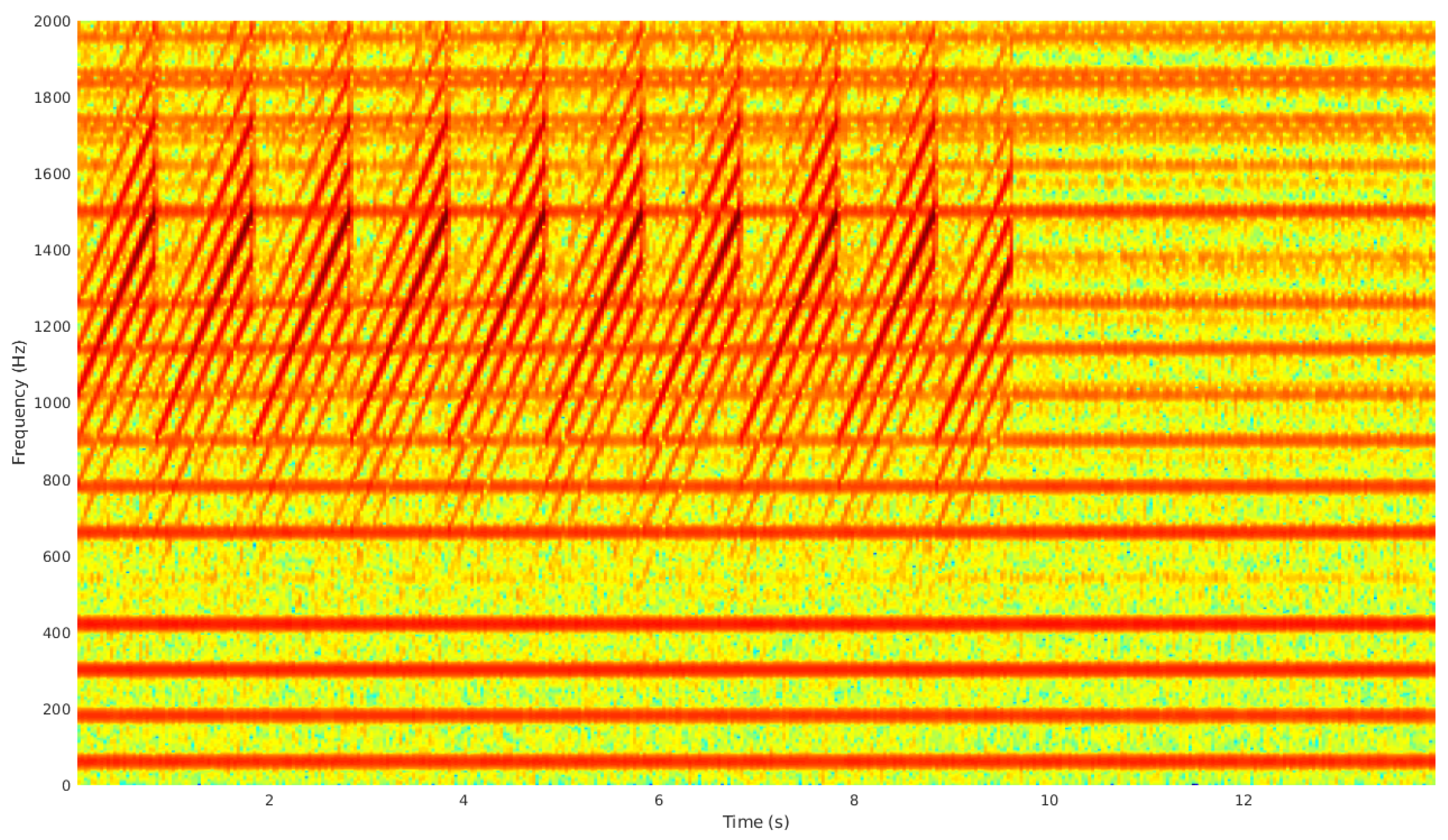
The importance of this process is described graphically via
Figure 8 and
Figure 9, which are the results of a prototype test of the approach described in this paper. In the prototype test, a complex current disturbance or “DCP” was introduced into a conventional 120 Vrms outlet using a programmable current source, as previously indicated. The outlet was serviced by a single phase (Phase A) via a split-phase lateral derived from a 13kV, three-phase feeder (Phases A, B, C).
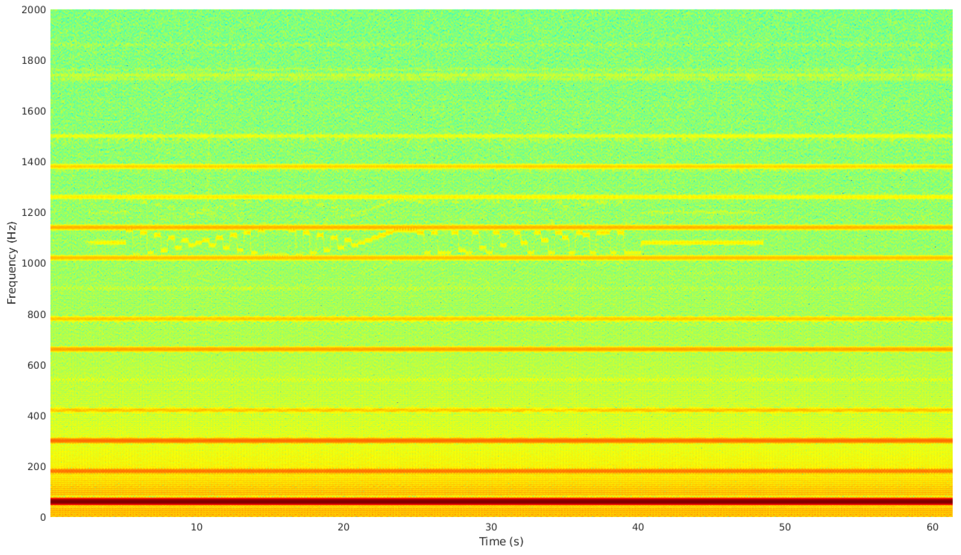
Figure 8 shows the flow of current on the feeder in the form of a spectrogram, which is a convenient visualization of the time-varying magnitude of spectral activity. The horizontal axis of the spectrogram is “time” and the vertical axis is “frequency.” The spectrogram shows the set of magnitude spectra for sequential, overlapping frames of acquired data, arranged in time sequence and viewed “from above.” In the figures, green is “low magnitude” and dark red is “high magnitude.” The spectrogram contains data from the UCP which corresponds to the DCP as it was presented in real time to Phase A of the feeder at the substation, after transiting the distribution grid from the low-voltage outlet to the high-voltage feeder at the substation. The figure clearly shows the fundamental at 60 Hz as a dark red, horizontal stripe. Similarly, the figure shows the odd harmonics of the fundamental at frequencies from 180 Hz (3rd harmonic) to 1500 Hz (25th harmonic) as horizontal stripes with shades of orange which vary as their magnitudes change with frequency.
The DCP is evident in
Figure 8 as a complex sequence of frequency-shifted and amplitude- modulated tones between 1020 Hz (17th harmonic) and 1140 Hz (19th harmonic). Even though the DCP was introduced into Phase A,
Figure 9 clearly shows cross-talk between phases, which has previously been described in detail in
Section 5.2. The cross-talk is produced between phases as the DCP disturbance transits the distribution network towards the substation.
Figure 9 contains bandpass-filtered spectrograms for Phase A (bottom), Phase B (middle), and Phase C (top). The DCP is clearly present in all three phases.
The utility of the approach proposed here is subtle, but important. By trapping an abstract description of the DCP at the emulated smart meter and transmitting it to the substation for comparison with the UCP, determination of the specific phase of the feeder which services the meter where the DCP originated is very simple. In effect, the proposed approach disambiguates which feeder is servicing each meter in the service territory, and does so in real time. This is an element of situational awareness that utility operators do not currently enjoy, as described in
Section 3.2 and
Section 3.3. This element of situational awareness, including real-time disambiguation of feeder/phase and the set of meters being serviced by specific feeder/phase combinations, can be directly leveraged in optimizing voltage and implementing a more complete
system.
8.2. Disturbance Disambiguation
In addition to phase disambiguation and reconciliation of meter location (geospatial, electrical), the approach proposed here provides a mechanism for pinpointing objectionable disturbances which may produce IEEE-519 violations [
51]. An example of this process is described graphically by the spectrogram shown in
Figure 10.
The current disturbance (DCP) presented in
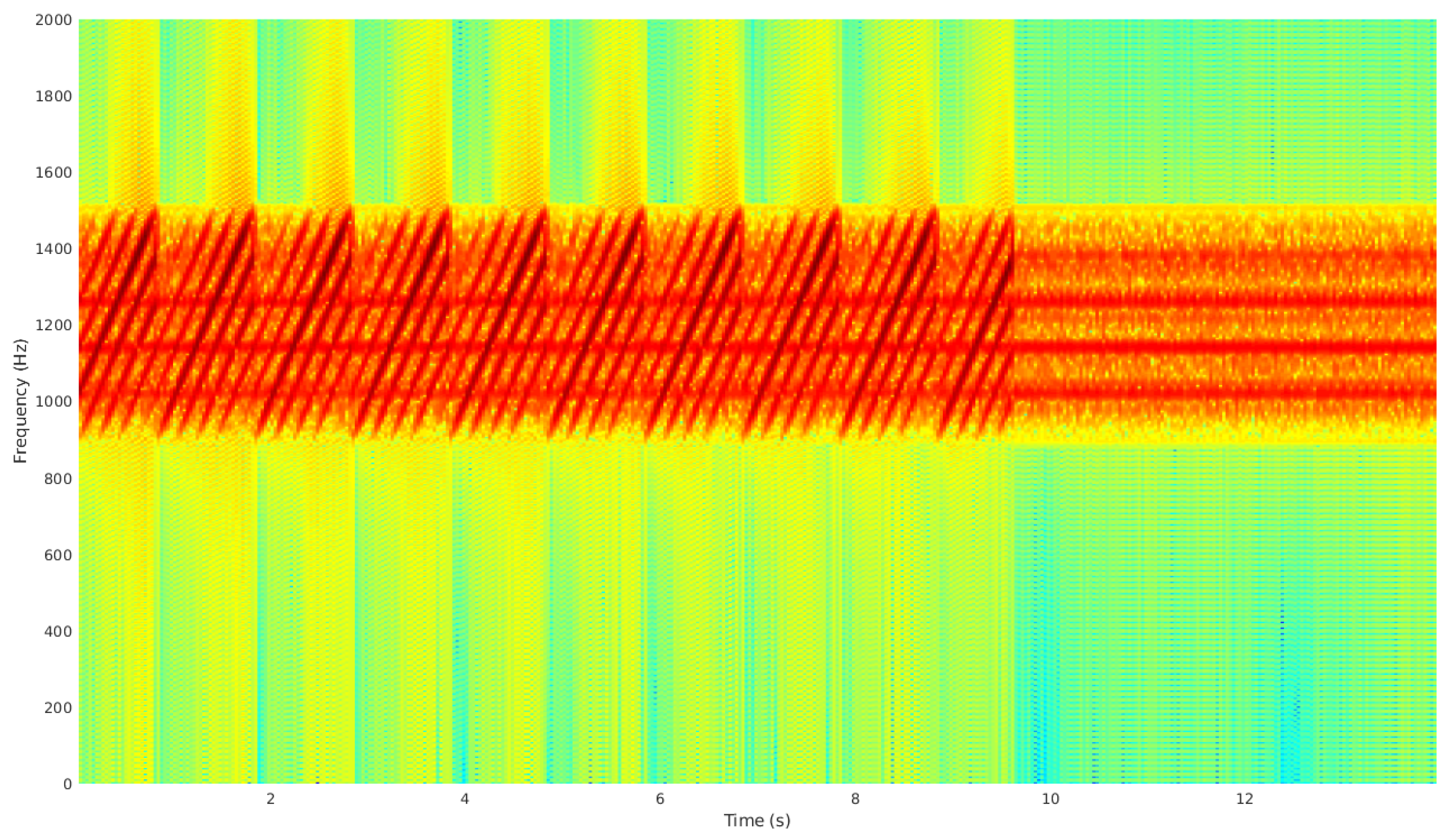
Figure 10 is a “sweep” or “chirp” of current which repeatedly transitions from around 900 Hz to around 1500 Hz in 1-second intervals. The “sweep” DCP is clearly evident in the UCP of
Figure 10, but the cross-talk between phases is very intense. As a result, the original or “primary sweep” is almost undetectable, and the phase which produced the “primary sweep” is difficult to determine. As in the discussion of the issues associated with phase disambiguation in
Section 8.1,
Figure 11 presents a bandpass-filtered perspective of the UCP, which may assist in a manual determination of the “primary sweep” which has a relatively higher magnitude than the synchronous harmonic distortions or “sidelobes” described in
Section 5.2. However, automated mechanisms which use ML techniques to assist in phase disambiguation as well as determination of original artifacts could be extremely valuable. For example, the presence of the “primary sweep” can be easily detected by the smart meter which services the originator of the artifact. Such artifacts can be decomposed in a variety of ways to create the DCP description which assists in localizing and identifying the presence of the DCP in the UCP sequences captured at the substation.
9. Conclusions
While CVR and other techniques have been postulated for many years, the issues of deployment have always led to roadblocks. Several of these roadblocks have caused promising solutions to be shelved. In today’s rapidly changing smart grid arena, there are enabling technologies that effectively address the roadblocks, and can make cost-effective, functional deployments a reality. By leveraging modern signal processing technology and grid-location-aware sensors, large-scale deployments can be implemented accurately and effectively, while providing numerous other system benefits. Employing cost-effective sensors at the customer premises eliminates the danger of reducing the supplied voltage below regulatory limits and enabling “high definition” with in-line control points (voltage regulators, capacitors and other voltage control devices on the power line). Furthermore, by incorporating ML algorithms and constant feedback for the real-time data gathered from the “high definition” system, voltage level control can be optimized over a wider range of operational conditions and dimensions of the dataset, which maximizes the potential for voltage reduction and power savings.
In short, we believe that an ML-based approach to can be valuable, particularly when driven by incomplete data from service endpoints, accumulated over time, and providing a unique approach to “unwinding” both geospatial and schematic “locations”. Specifically, the upstream/downstream correlation paradigm presented here has two primary benefits:
In addition to the DCP correlation template, out-of-band messaging from the smart meter which traps the DCP also carries geospatial information, time information, and other deployment context which can be lost or corrupted during construction or emergency events. Thus, the smart meter “identifies itself” to the correlation algorithm(s) via logistical data as well as operational data which directly indicates presence on a specific feeder and phase.
The fact that the DCP travels intact to the substation and can be used to identify the feeder and path of electrical deployment [
36] means that the DCP/UCP correlation “completes the picture” to provide robust, real-time situational awareness for the grid operator.
The implementation of the proposed architecture alongside an existing CVR deployment would be straightforward, and the two system outputs would be complementary. The fact that the architecture proposed here leverages already-deployed “smart meters” to provide information to upstream systems for geospatial and schematic location refinement is significant. This approach can be leveraged alongside CVR systems to implement a richer form of .
10. Patents
Location mapping of grid devices using features of passively-observed current disturbances (PCT/US2015/014603, WO2015120141A1) [
30]
Suppression of interference in power and communication signals (USPTO 9,876,516) [
39]
Intelligent power system and methods for its application (USPTO 8,519,832) [
38]
