Article

Microstructural, Surface Topology and Nanomechanical Characterization of Electrodeposited Ni-P/SiC Nanocomposite Coatings

by
Konstantinos Tsongas
1,*,
Dimitrios Tzetzis
1,2,
Alexander Karantzalis
1,3,
George Banias
1,
Dimitrios Exarchos
1,
Donya Ahmadkhaniha
4,
Caterina Zanella
4,
Theodore Matikas
1,3 and
Dionysis Bochtis
1
1
Center for Research and Technology - Hellas, Thessaloniki, Institute for Bio-Economy and Agri-Technology, 57001 Thessaloniki, Greece
2
School of Science and Technology, International Hellenic University, 57001 Thessaloniki, Greece
3
Department of Materials Science and Engineering, University of Ioannina, 45110 Ioannina, Greece
4
Department of Materials and Manufacturing, Jönköping University, 55318 Jönköping, Sweden
*
Author to whom correspondence should be addressed.
Appl. Sci. 2019, 9(14), 2901; https://doi.org/10.3390/app9142901
Submission received: 4 June 2019 / Revised: 11 July 2019 / Accepted: 12 July 2019 / Published: 19 July 2019
(This article belongs to the Section Materials Science and Engineering)

Abstract

:
In the present study, nickel phosphorous alloys (Ni-P) and Ni-P/ silicon carbide (SiC) nanocomposite coatings were deposited by electrodeposition on steel substrates in order for their microstructural properties to be assessed while using SEM, XRD, and three-dimensional (3D) profilometry as well as nanoindentation. The amorphisation of the as-plated coatings was observed in all cases, whereas subsequent heat treatment induced crystallization and Ni3P intermetallic phase precipitation. Examination of the surface topology revealed that the surface roughness follows the deposition characteristics and heat treatment induced microstructural changes. Additionally, substantial improvements in mechanical properties, including hardness, yield stress, and elasticity modulus, were obtained for the Ni-P, Ni-P/SiC nanocomposites when heat treated as seen from the nanoindentation results. A Finite Element Analysis (FEA) was developed to simulate the nanoindentation tests that enable the precise extraction of the Ni-P and Ni-P/SiC nanocomposite coatings’ stress-strain behavior. It is shown that the correlation between the nanoindentation tests and the computational models was satisfactory, while the stress-strain curves revealed higher yield points for the heat-treated samples.

Graphical Abstract

1. Introduction

Wear, friction, and corrosion are surface phenomena that have been early characterized as degradation mechanisms that may lead to catastrophic results reducing the performance and the life cycle of components and various industrial equipment, under extreme conditions. The development of coatings has been recognized early as one of the most promising and effective process towards this direction. The excellent wear and corrosion resistance of the Ni-P (nickel-phosphorous) coatings makes them very good candidates for application where surface is under load and aggressive environment [1,2,3,4]. The two major deposition techniques for Ni-P coating systems are the electro- and electroless deposition, with the first to provide high deposition rates and the second to provide coatings of exceptional thickness uniformity, even at the complicated geometrical features [1,2,3,4,5].
The development of the electroplating technology is established many decades ago and parameters, such as bath pH values, bath temperature, and current density, are of the most crucial factors affecting both the process and the final coating characteristics. The continuous development of the electroplating technology has recently led to a new electrodeposition approach that is known as pulse current electrodeposition, where some additional process parameters play a key role in deposition control. Among these, tON, which is the time that the current is on, tOFF the time the current is off, the duty cycle as the ratio tON/tON+tOFF, and the frequency of the cycle (f), which is defined as the ratio f = 1/tON+tOFF control the nucleation and growth of the coatings [6]. Pulse current provides some important advantages, such as: a) a negatively charged region is formed, upon plating, close to the cathode that obstructs metal ions from reaching its surface. In pulse current, during the tOFF time, this layer of negative charge is partially discharged and the migration of ions is improved in such way, b) upon the tOFF period, areas within the bath that have been depleted of metal ions can recover the bulk concentration, so to increase mass transport and increase the limiting current density value, and c) careful control of both the typical plating parameters along with the pulse current parameters can improve the coating final properties with more compact structure and controlled microstructure and thickness distribution [6].
The outstanding characteristics in the performance of Ni-P coatings are mostly related to their microstructure, which is affected by the P content. Low P content (<4% wt) lead to crystalline coatings, medium additions of P to coatings lead to partially crystalline, and partially amorphous nature and high P level (> 10% wt) leads to fully amorphous coatings [7,8,9,10,11,12]. Often, these coating are heat treated to increase their hardness by precipitation hardening. This heat treatment process lead to the crystallization of the amorphous phases and the precipitation of the supersaturated P lead the final microstructure to a Ni Face-Centered Cubic (FCC) matrix and Ni3P intermetallics [13,14,15,16]. It has been reported that post heat treatment close to 400 °C drastically increases the coating hardness due to the strengthening effect that was caused by the precipitation of Ni3P intermetallic particles [17,18]. The strengthening effect fades at higher treatment temperatures due to the coarsening of the precipitated particles, coarsening of matrix grains, and due to the reduction of the crystal lattice defects.
The Ni-P coatings were further evolved and enhanced towards the development of Ni-P composite coatings due to the continuous increase in the demand for improved wear and corrosion resistance, where parallel deposition of Ni-P matrix and embedment of hard particles occurs. Various systems have been developed so far of exceptional in some cases properties. Indicative systems with reinforcing phases, such as Al2O3 [19,20,21,22,23], SiO2 [24], Cr2O3 [25], ZnO [26], SiC [27,28,29], B4C [30], WC [31], CNTs [32,33], Graphite [34], BN [35], Diamond [21,33], Si3N4 [27,36], CeO2 [37], MoS2 [38,39], PTFE [40,41], and combinations of them [42,43] are reported.
The hardness of coatings is of crucial importance and its optimization and improvement is strongly associated with other important properties, such as friction behavior and wear resistance. Various research efforts that are reported in the literature show that the increase of the embedded particle concentration leads to an increase of the overall coating hardness in the case that hard reinforcing particles are co-deposited (carbides, oxides, nitrides) [23,24,25,26,27,37,38] and they may decrease the overall hardness, if soft particles are co-deposited (PTFE for example) [40,41]. However, the main hardness increase is achieved with the post heat treatment.
The nanoindentation technique can also been applied for the determination of the mechanical properties of nanocomposites, and specifically of surface layers and coatings. This technique can provide valuable data regarding the mechanical behavior of materials. Several papers have compared the nanoindentation results with the results that were acquired from classical tensile tests and especially for the elastic modulus calculation [44,45,46]. The nanoindentation tests have been used in the past for the investigation of coatings materials. More specifically, Wang et al. [47] used nanoindentation tests for the assessment of the mechanical property response of the Ni-P coatings and composites and for the mechanical response of Ni-P-TiO2 coatings. They observed that density and elastic modulus were both improved by the insertion of TiO2 nanoparticles, with this improvement, nevertheless, fading by exceeding and optimum concentration above which particle agglomeration phenomena lead to a gradual decrease of such properties. Alexis et al. [17] also studied the mechanical properties of the Ni-P electroplated coatings that were reinforced with SiC particles. This showed that the particle presence does not significantly alter the modulus of elasticity of the plain coatings and that the hardness was slightly improved. They associated behavior with the effectivity the particles have in their strengthening effect, which is related with their size and/or their agglomeration behavior. The same authors [48] also studied, with the use of nanoindentation testing, the effects that talk phyllosilicate particles have on the mechanical properties of Ni-P coatings. They observed that, for the as plated condition, the presence of these particles decrease the hardness due to their intrinsic soft nature. Improvement was observed after heat treatment, which was rather an effect of matrix crystallisation and precipitation phenomena than being due to the presence of particles. Wang et al. [49] studied the effect of Multi Wall Carbon Nanotubes (MWCNTs) at different annealing conditions within the same frame of improving the mechanical properties of Ni-P coatings. Their nanoindentation results showed that the presence of MWCNTs improves the hardness up to certain annealing temperature range above which grain growth and coarsening phenomena of the precipitated Ni3P phases lead to a gradual reduction. Birlik et al. [50] examined the effect of TiO2 nanoparticles on the mechanical properties of Ni electrodeposited coatings. They observed that, the smaller the particle size, the more effective the strengthening effect of particles. However, this enhancement, as the authors showed, is not independent of other crucial processing parameters that can alter other microstructural features, such as grain size and boundaries, which also may play a vital role in the overall mechanical response. Tien et al. [51], using nanoindentation technique showed the beneficial action annealing exhibits on the hardness of Ni-P-W electrolessly deposited coatings. Islam et al. observed profound increase of the nanohardness of electroless Ni-P coatings due to the incorporation of SiC particles [52]. This beneficial action was attributed both to the alteration of the microstructural morphology (refinement of the nodular morphology) and plastic deformation restriction that the SiC particles may induce.
In the present paper, Ni-P pulse current electroplated coatings with SiC nanoparticles were developed and their microstructure and surface topology were assessed while using scanning electron microscopy (SEM), X-ray diffraction (XRD), and three-dimensional (3D) surface profilometry. The nanocomposite coatings were also studied and tested in terms of mechanical performance by an instrumented nanoindentation measurement at room temperature. The experimental results were fitted with a finite element model (FEM) that simulated the nanoindentation test, in order to extract the stress-strain behavior of Ni-P and Ni-P/SiC nanocomposite coatings.

2. Materials and Methods

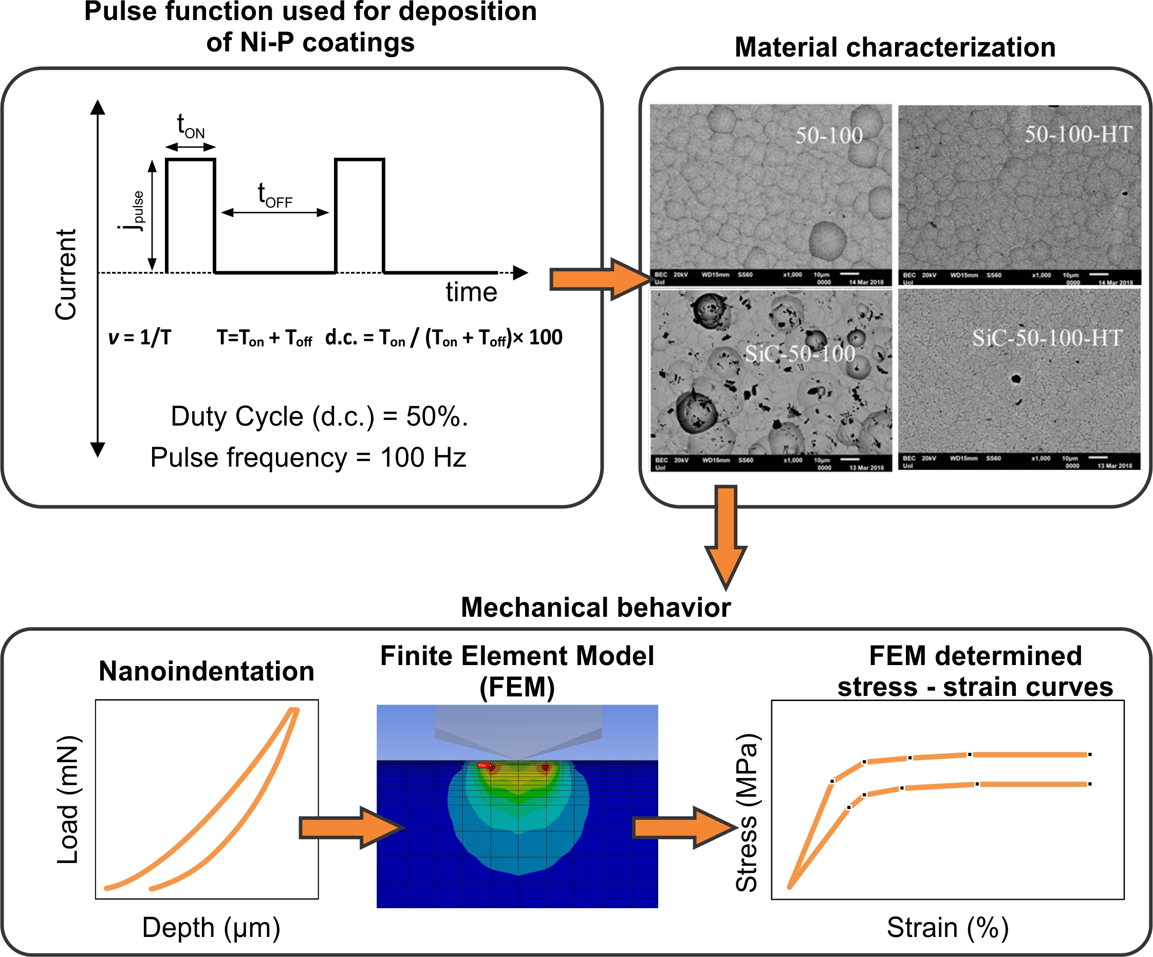
2.1. Materials and Electroplating Process

Pulse electrodeposition of Ni-P, at 4 A/dm2 average current density on C50 steel substrates (50 mm × 50 mm × 0.8 mm), was applied from a modified Watts bath at 70°C with nickel anodes. The composition of the plating bath contained NiSO4·7H2O, NiCl2·6H2O, H3PO3, H3BO3, and two additives (saccharin and sodium dodecyl sulfate). The ratio of Ni2+/PO33− was 3.25 and the pH of the bath was adjusted to 2.15 before each plating by adding sulfuric acid or sodium hydroxide. The electrodeposition cell was set up with two vertical planar electrodes and magnetic stirrer at 250 rpm agitated the bath. To produce composite coatings 20 g/l of silicon carbide particles (β-SiC, Get Nano Materials) with average size of 100 nm were added in the bath, which was stirred for 24 h before plating, as well as during plating. In pulse deposition experiments, the frequency of the imposed pulses was set at 100 Hz, while the duty cycle (d.c.) of the pulses [i.e. d.c. = tON/(tON + tOFF), where ton is the time period the pulses are imposed and tOFF is the relaxation time] was 50 %. The samples were heat treated in air at 400 C for one hour.

2.2. Morphological Characterization Methods

The surface morphology of Ni-P and Ni-P/SiC coatings was qualitatively examined by using a JEOL JSM-5600, UK scanning electron microscope (SEM) and composition by EDX X-Ray type Link ISIS 300 (Oxford Instruments, UK). Further examination of the microstructural features was conducted through the use of XRD diffractometer (Siemens D500, Germany) with auto divergent slit and graphite monochromator while using Cu Kα radiation, and a scanning speed of 2° min−1.
The surface topology was investigated through the use of white light profilometer (TMS-1200, Polytec, Germany) with a resolution single root mean square (RMS) of 3.65 nm This profilometer provides a rapid and non-contact two or three-dimensional micro-topography functional surface and microstructure of the tested materials. The area of interest is the same of every specimen of dimensions 2.24 mm × 1.67 mm.

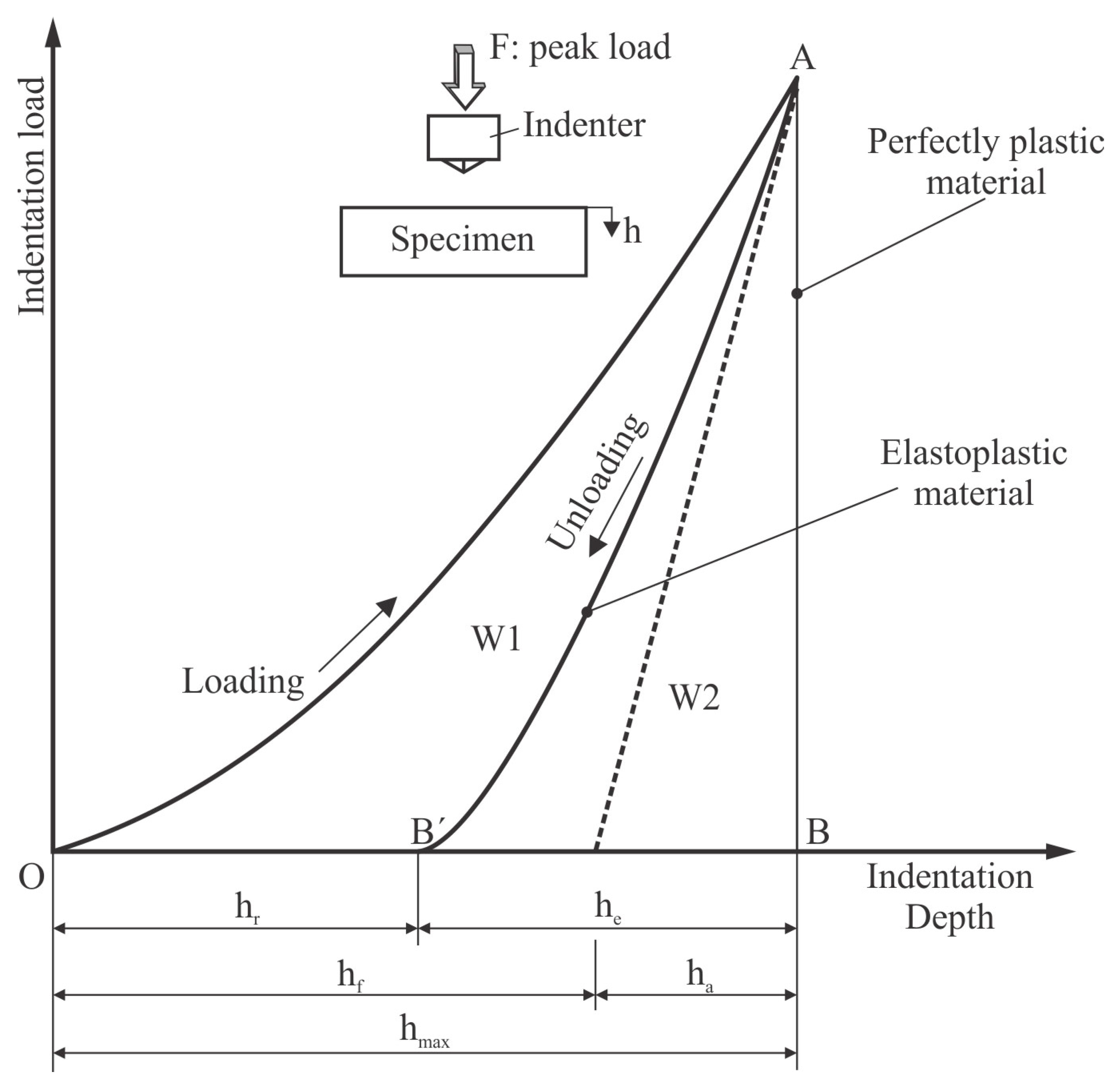
2.3. Nanoindentation Tests

Instrumented indentation was applied in order to determine the mechanical behavior of the under-study coatings. Nanoindentation tests implicate the contact of an indenter to a material’s surface and its penetration to a predetermined depth or load. The indentation force is measured along with the penetration depth. Figure 1 illustrates a typical loading and unloading procedure, presenting the parameters that are needed to characterize the contact geometry. This figure shows a standard elastoplastic material with the loading OA and unloading AB´ segments. The area W1 (OAB´) represents the plastic work that is done in the elastoplastic case. The area W2 (ABB´) corresponds to the elastic work that is recovered during the unloading segment. The unloading curve is a straight line (AB) and hr = hmax (W2 = 0) in the case of purely plastic material. In this case, penetration depth is the displacement into the sample starting from its surface [45,53,54,55].
The nanoindentation tests were performed on a Shimadzu DUH211S device with a resolution of 0.2 μN. The indenter was a Berkovich diamond tip (the tip shape is a three-sided pyramid, with a triangular projected geometry and an included angle of 65.3°; tip radius 0.1 μm). Several points were selected while using an optical microscope implemented to the indenter and these were distributed on the surface of the coating. At least twenty measurements were performed per coating sample.
Preceding a nanoindentation test, the indentation tip is driven toward the specimen surface. After contact is achieved, the indenter penetrated the surface, to a depth around 1.3 μm, with a constant loading rate of 70 mN/s, until a maximum force of 200 mN. As soon as maximum force was reached, the indenter was removed with the same loading rate to a value of zero.
The modulus and the hardness of the coatings were determined based on the work of Oliver and Pharr [56]. The indentation hardness can be determined as a function of the maximum penetration depth by [45,53,54,55]:
H = P m a x A
where Pmax is the maximum applied load that was measured at the maximum depth of penetration (hmax) and A is the projected contact area between the indenter and the specimen. For a perfect Berkovich indenter, A can be expressed as a function of the contact indentation depth hf as:
A = 3 3 h f 2 t a n 2 65.3 = 23.96 h f 2
The contact indentation, hf, can be determined from the following expression:
h f = h m a x ε P m a x S
where ε is a geometric constant ε = 0.75 for a pyramidal indenter and S is the contact stiffness that can be determined as the slope of the unloading curve at the maximum loading point, i.e.
S = ( d P d h ) h = h m a x
The reduced elastic modulus Er is given by:
E r = S 2 β π A
where β is a constant that depends on the geometry of the indenter. For the Berkovich indenter, β = 1.034. The specimen elastic modulus (Es) can then be calculated as:
1 E r = 1 υ s 2 E s + 1 υ i 2 E i
where Ei,s, and νi,s are the elastic modulus and the Poisson’s ratio, respectively, for the indenter and the specimen. For a diamond indenter, Ei is 1140 GPa and νi is 0.07. The specimen’s hardness H and elastic modulus Es were obtained from the set of equations given above.

3. Results and Discussion

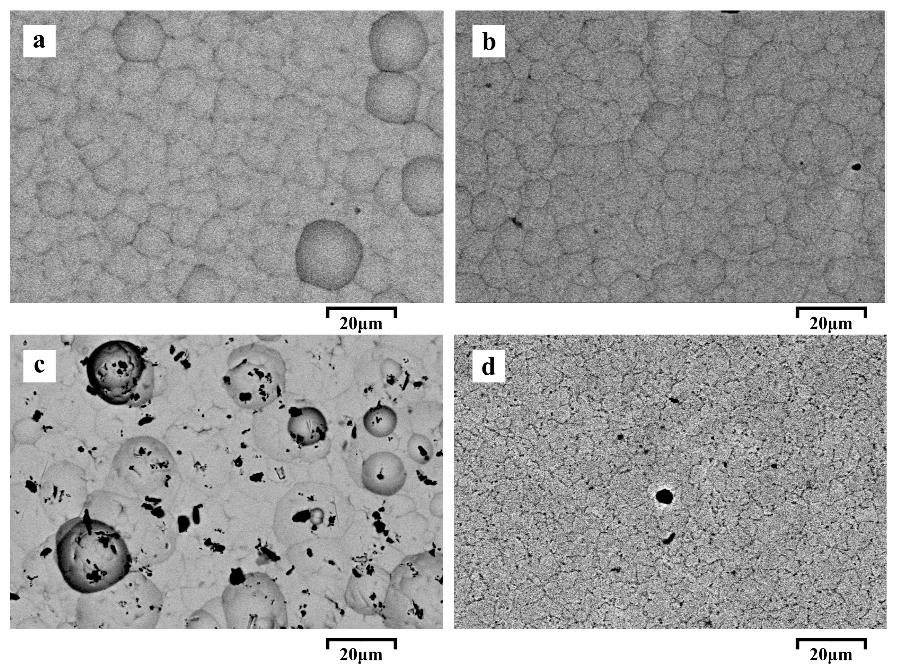
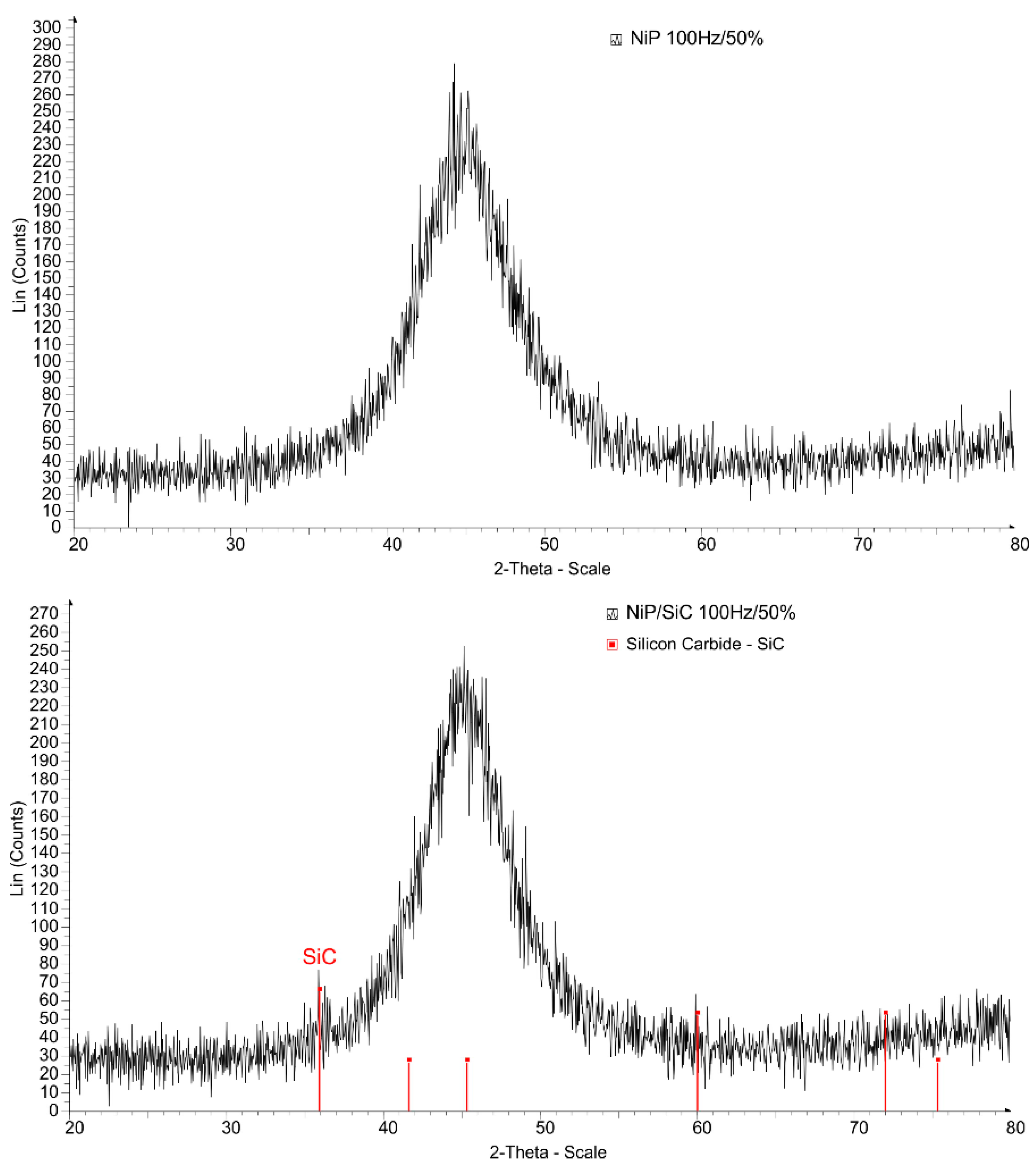
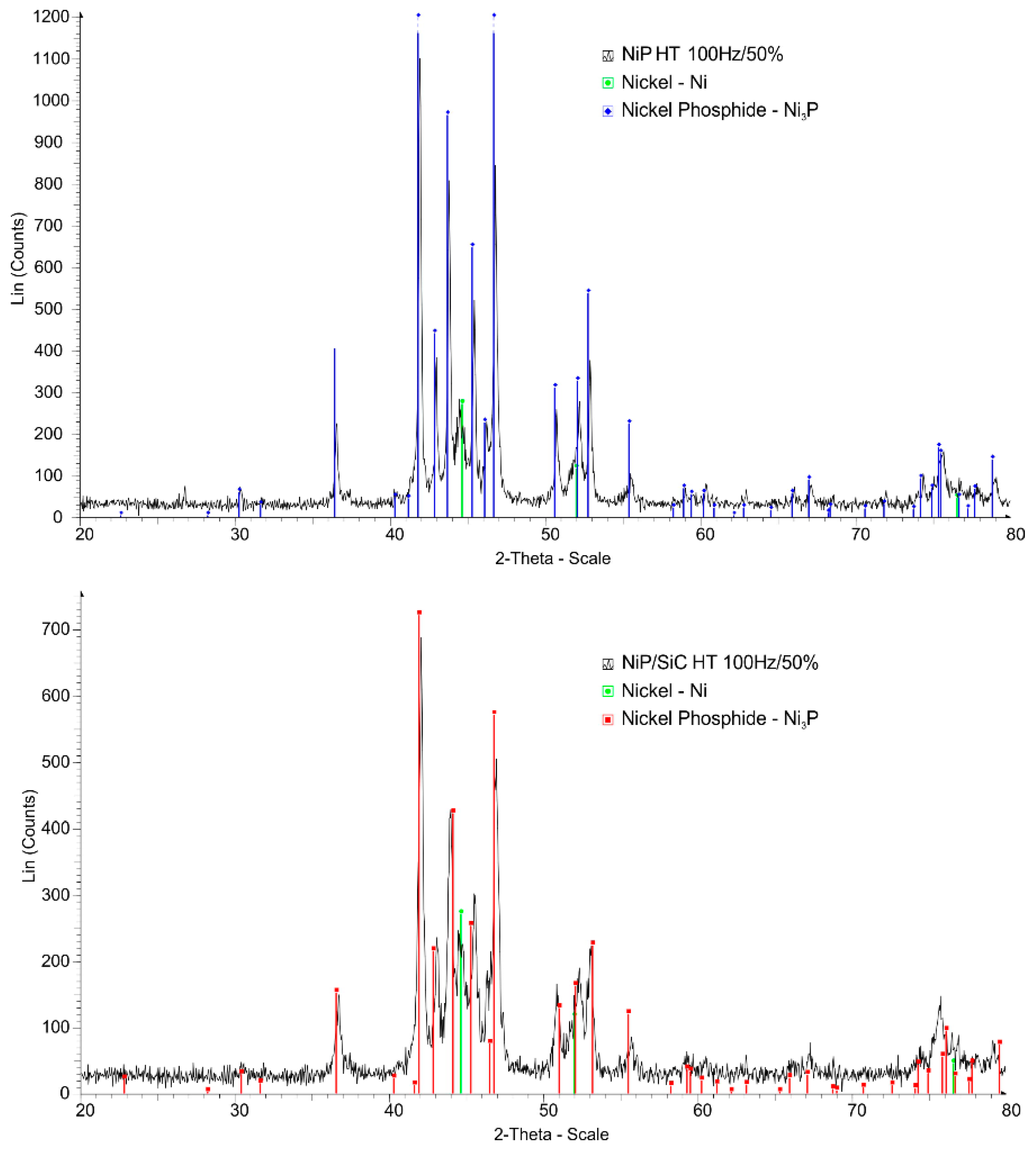
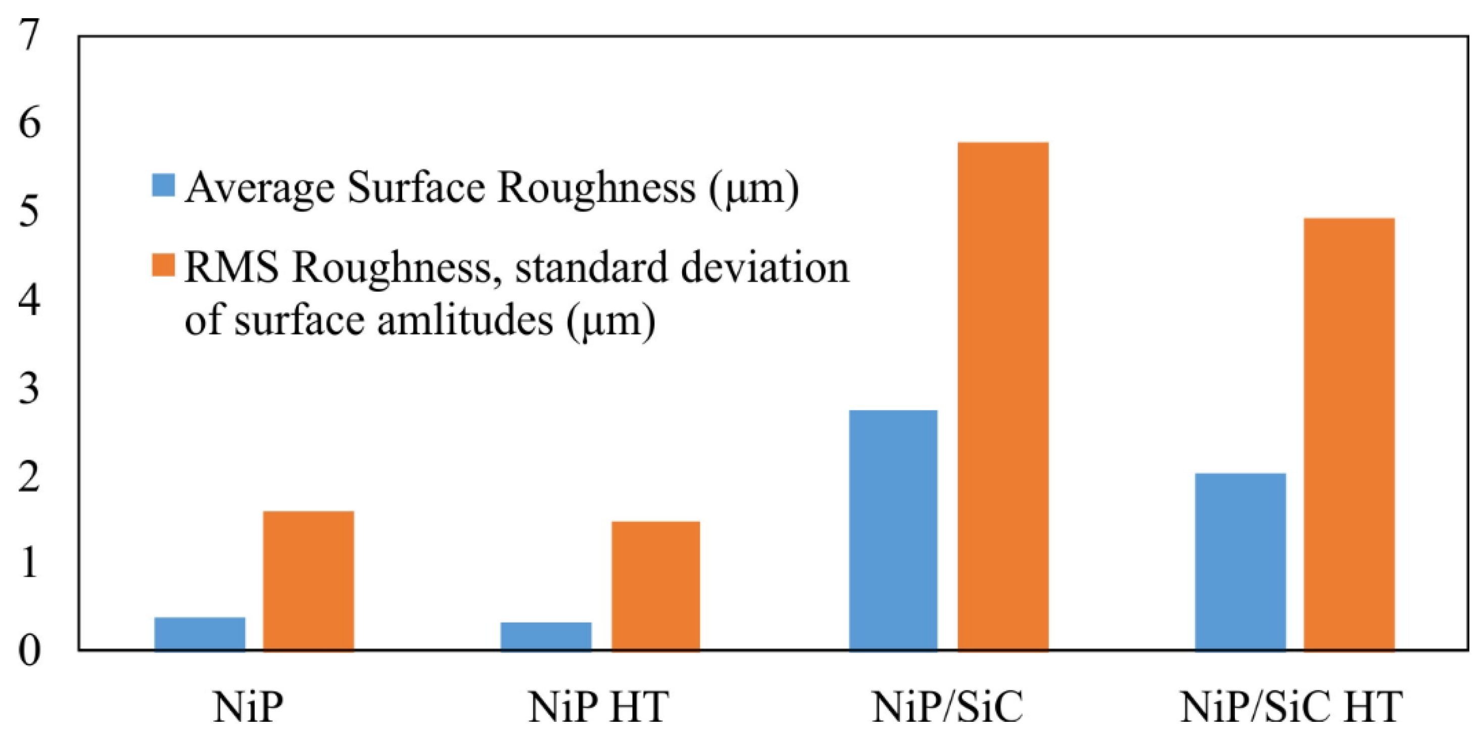
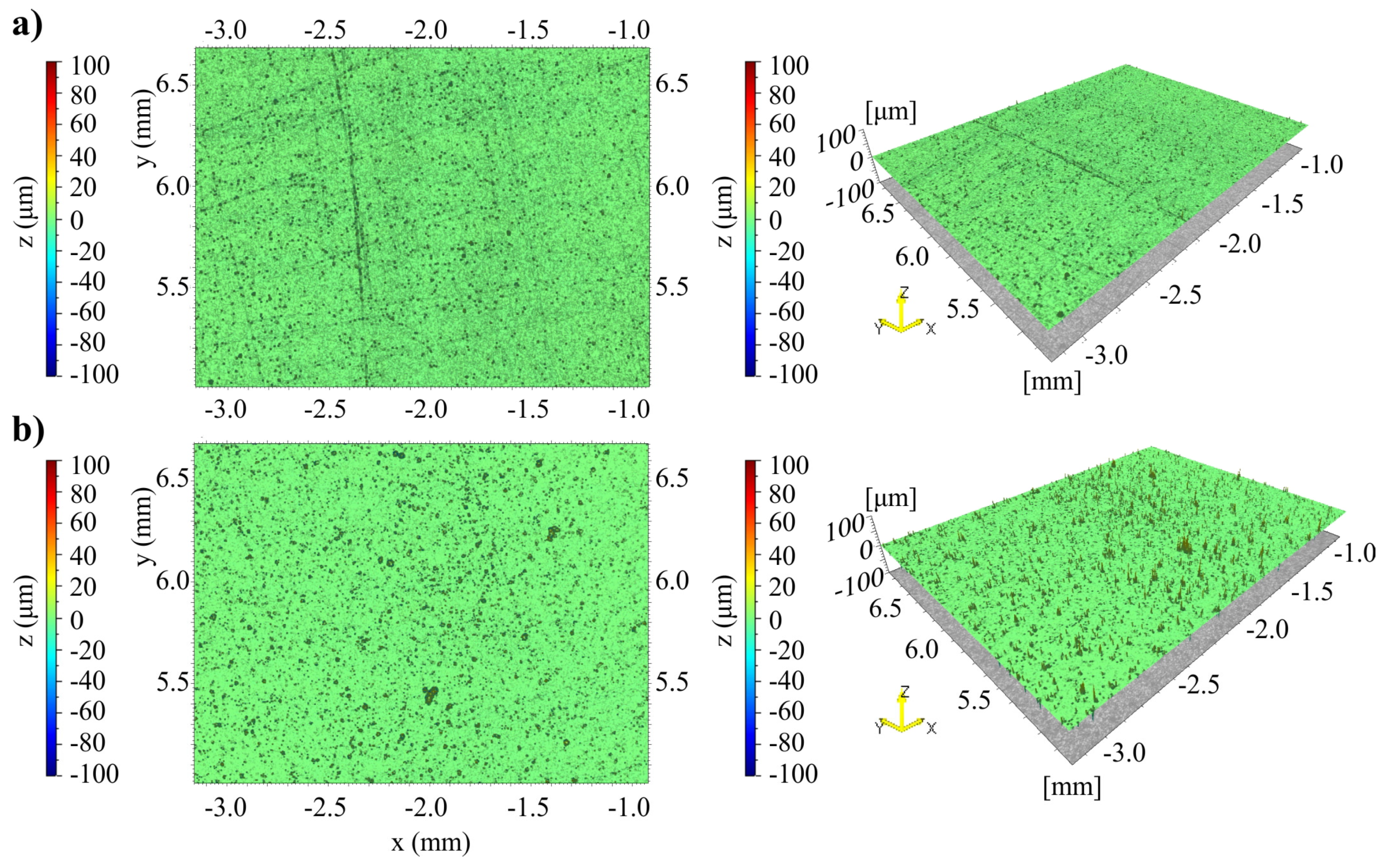
3.1. Characterization of Coatings

Figure 2 shows the panoramic view of the surface morphology from different samples. Back scattered mode was applied to highlight residual particles on the surface. The Ni-P coatings with no SiC additions exhibit a characteristic nodular cauliflower—like morphology. Nevertheless, all samples show a surface that is smooth, of limited defects, which, if present, are most likely located at the interception points of the spherical nodules. Additionally, no severe morphological alterations of the surface characteristics seem to be induced by the heat treatment of the plain Ni-P coatings, while the SiC particles introduction slightly affects the surface morphology. The SiC fraction was measured by EDS in different parts of the surface to assure a homogeneous deposition over the area, since the stirring conditions may affect the SiC particles incorporation. EDX’s analyses confirmed that the codeposited fraction of SiC is about 3% vol.
Figure 3 shows the XRD diagrams of the samples before heat treatment, while Figure 4 shows the similar analysis after heat treatment. Intensive SiC peaks can be distinguished. The XRD spectra of the non-treated specimens show the characteristic peak of the amorphous Ni-P structure that was also observed in other studies [1,2,3,4,5,42,43]. It has been reported that the amorphisation of Ni due to the high amount of phosphorus is due to the fact that P presence within the lattice and the subsequent strain fields it causes, lead to primary grain growth inhibition that becomes so intensive, so that practically nanocrystallinity and eventually amorphisation is achieved [1,2,3,4,5,6].
However, the overall structure has been totally altered after the application of heat treatment, as it can be seen in Figure 4. Narrow intensive peaks in all cases declare the crystallization process taking place during this stage. Phase identification does verify the crystallization process, which is also observed in many other cases [1,2,3,4,5], as crystalline Ni FCC phase is distinguished in all samples along with the presence of the precipitated Ni3P intermetallic phase, which is also a classical outcome of the heat treatment and crystallization process [1,2,3,4,5,6]. XRD did not reveal the presence of SiC phase in the case of heat treated samples as compared to the as-coated samples.
The surface topology of the resulted coatings is another very important parameter that it seems to be affected by the deposition process and its parameters. Figure 5 graphically shows the average surface roughness and the RMS roughness of the produced coatings before and after heat treatment, as measured from the profilometer. The introduction of reinforcing particles leads to an alteration of the coating surface smoothness. This effect is most likely associated with two combined mechanisms: 1) particle introduction leads to the appearance of surface imperfections, which make the surface landscape more intense and, as such, the roughness is increased, b) the particles themselves unsettle the continuity of the surface deposit and they consist site for deposition and nucleation of the metallic matrix. As particles perturb of the surface and since deposition follows the existed surface pattern and perturbation in electroplating, as the coating is built up, the initial perturbations due to particles become more intensive and, as such, the roughness may increase.
High particle entrapment means that their spatial inter-particle distance is reduced if homogeneity is considered in their location. At the same time, more uniformly distributed particles are embedded on the surface, i.e. more active nucleation sites of less distance between them. As such, the deposition of the metallic matrix will follow a pattern of many, close together initial perturbations and will, in turn, lead to a landscape that will not show that extensive landscape.
Heat treatment seems to have a dual effect. In the case of the plain coatings (no SiC reinforcement), heat treatment seems to increase the intensity of the surface landscape and, as such, the surface roughness. P incorporation during the plating stage induces amorphisation, as already mentioned [1,2,3,4,5,6]. This amorphisation is reported to be initiated by the severe crystalline grain growth restriction. Severe grain growth restriction leads to extreme grain refinement, nanocrystallinity, and amorphisation in order of appearance. Lack of crystalline grains means the lack of grain boundaries and a lack of preferential directional crystal orientation upon plating, i.e., a smooth surface finish and morphology. On the other hand, heat treatment induces crystallization, i.e., grain boundaries and preferential growth orientations, i.e., induces features that can account for the development of a distinguishing surface landscape.
Heat treatment causes an opposite effect in the case of the SiC reinforced coatings, since it significantly reduced the initial as-coated surface roughness. This tendency is most likely associated with the fact that the involved mechanisms during heat treatment have a beneficial effect on the healing the imperfections that are induced by the presence of particles in the as-deposited stated, according to what has been mentioned in previous paragraphs. Conclusively, in the case of SiC reinforced coatings, an initial high SiC content within the plated coating, along with the subsequent treatment, may lead to a smooth, uniform coating of low roughness and well accepted surface finish. Figure 6 shows a typical two-dimensional (2D) and three-dimensional (3D) surface reconstruction from the profilometry measurements, for the samples of non-treated Ni-P and heat-treated Ni-P/SiC electroplating coatings.

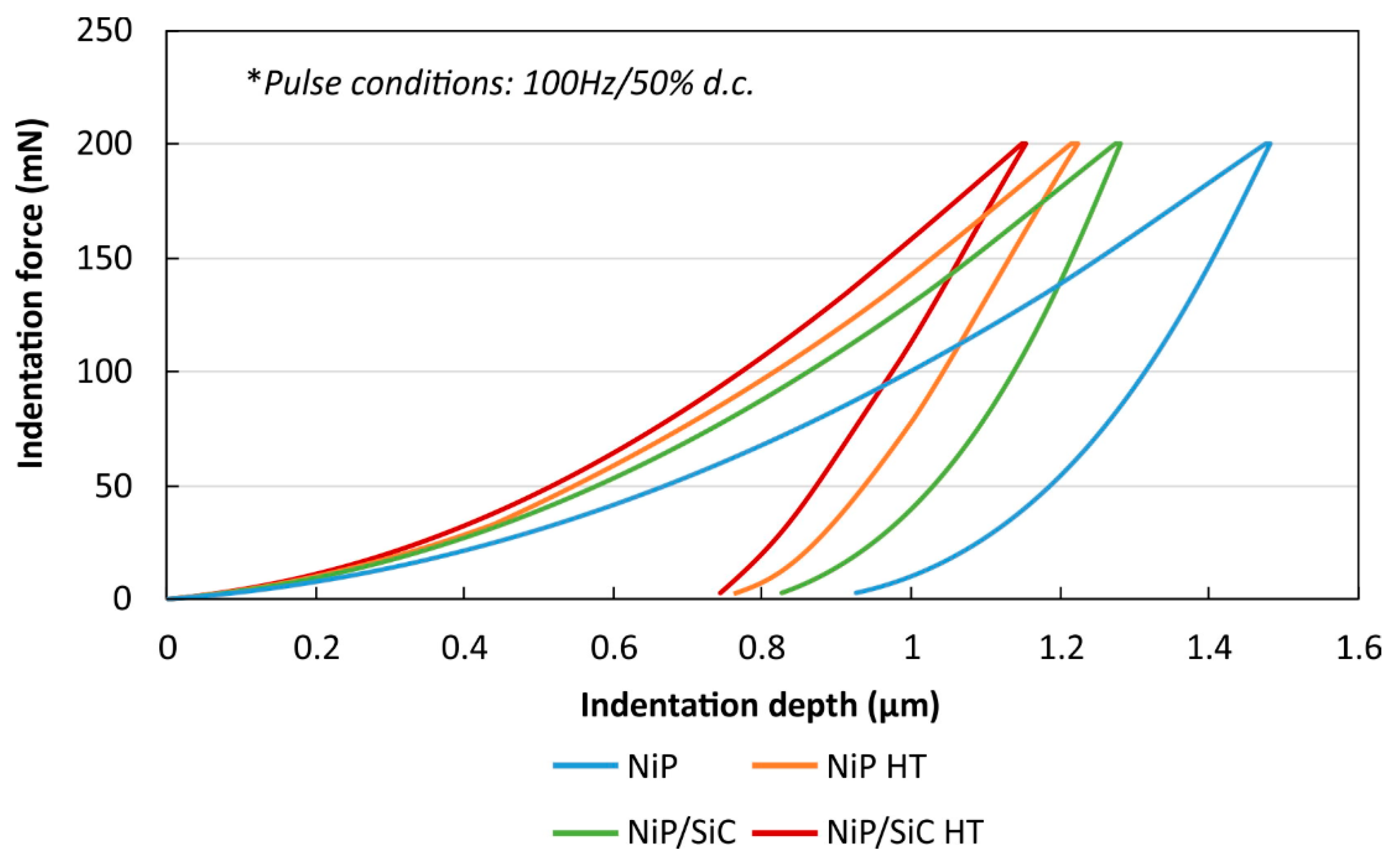
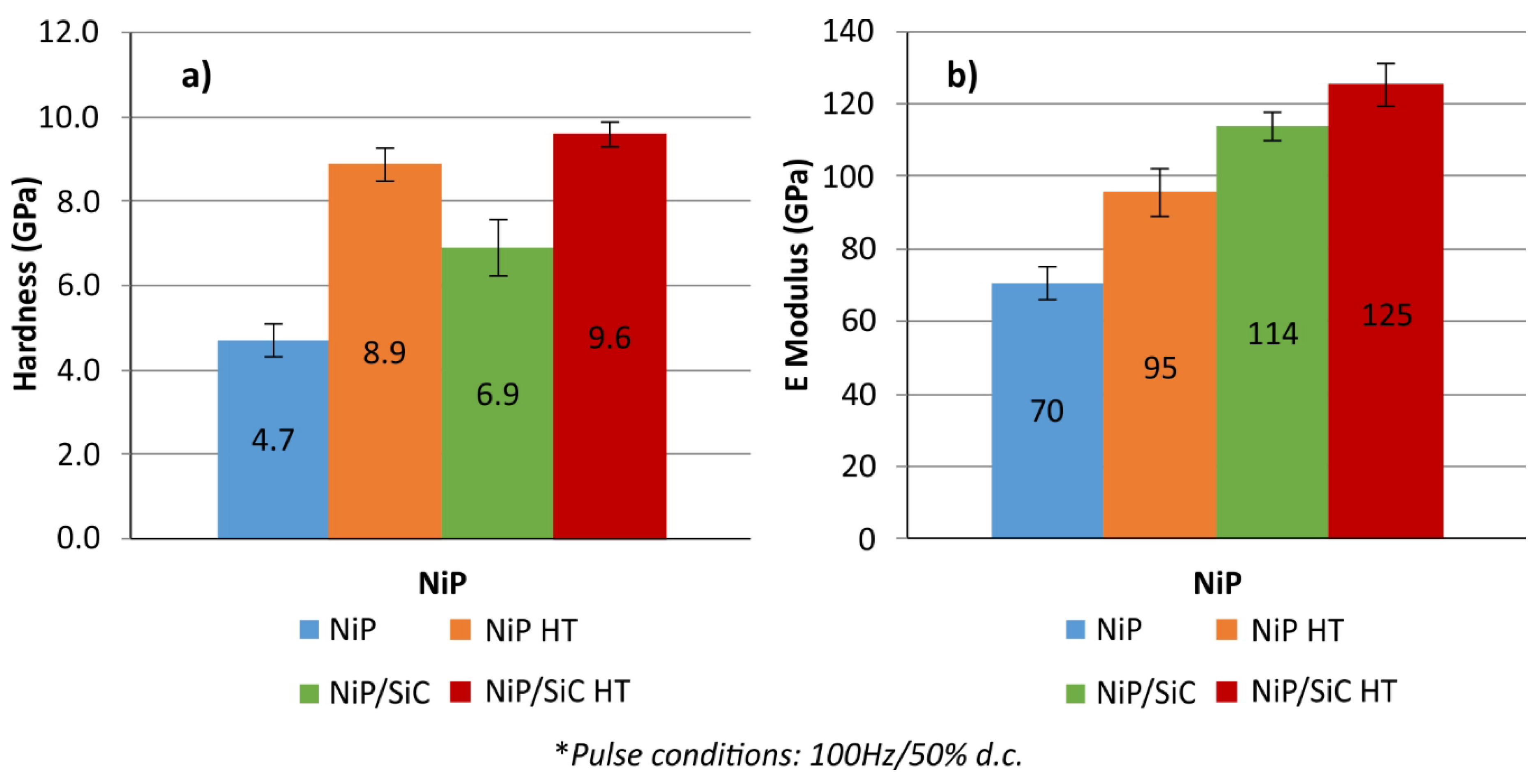
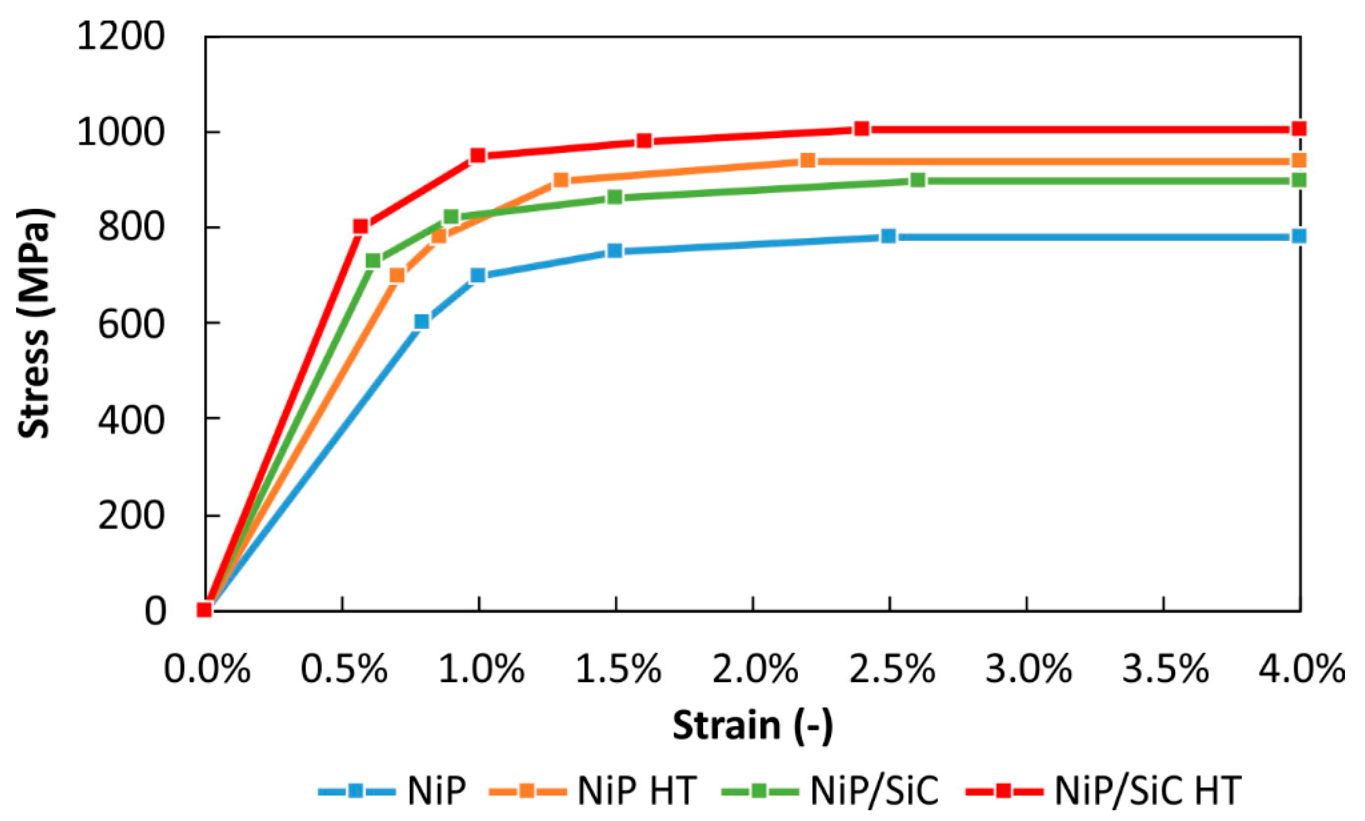
3.2. Characterization of the Mechanical Behavior

Figure 7 demonstrates nanoindentation load–depth curves that were conducted with a peak force of 200 mN of as-plated Ni-P, Ni-P/SiC nanocomposite coatings, and those heat-treated at 400 °C. The diagram corresponds to the plot of the moving average values (from 20 measurements) of the indentation load and the depth. There were not any visible cracks formed during the nanoindentation, since there are no discontinuities that were noticed by the loading-unloading curves. The maximum indentation depths at the peak load were varied from around 1.1 to 1.5 μm. The results clearly show the stiffening effect that SiC introduces into the Ni-P. Furthermore, there is an obvious stiffening effect between the heat-treated and non-heat treated coatings. The lowest values of indentation depths were detected for the heat-treated Ni-P/SiC nanocomposites, while the highest depths were observed for the non-heat treated Ni-P coating.
The hardness (H) and the elastic modulus (E) of as-plated Ni-P, Ni-P/SiC, and heat-treated coatings were calculated from the load-displacement curves. Figure 8 demonstrates the calculated mechanical properties, as elastic moduli and hardness, for all of the under study samples. The as-plated Ni-P coating shows the lowest hardness (Figure 8a). The incorporation of SiC nanoparticles increased the hardness of Ni-P, from 4.7, up to 6.9 GPa. The heat-treated coatings exhibited a higher average hardness, 8.9 and 9.6 GPa. The hardness increase is attributed to the formation of a hard Ni3P phase, as seen from the XRD results and as reported elsewhere [51]. In the case of the elastic modulus as shown in Figure 8b the effect of SiC codeposition is higher than heat treatment as Ni/SiC has higher elastic modulus values than both as-plated and heat treated Ni-P.
The data that are reported in Figure 8 are in a good agreement with the results of other experimental efforts, since the literature [3,47,48,49,50,51,52] reports values for the as plated, untreated condition of plain Ni-P coatings for hardness, ranging from 4 to 8 GPa, depending mainly on the P content and the processing parameters that were adopted. These values can rise to 12 GPa after heat treatment depending also on the P content and the temperature of annealing. When various reinforcing particles are introduced, the as-plated values seem to lay between 6 and 10 GPa, depending on particle type, morphology, and content and processing parameters. Subsequent heat treatments raise these values up 12 GP, additionally depending on the temperature of the process.
As far as the modulus of elasticity is concerned, the values for the as-plated Ni-P coatings of 100–150 GPa are reported and can be slightly increased after heat treatment [49,50,51,52]. P content and processing parameters are also the key factors that affect the values of elastic modulus. The values of the present effort are somehow lower, which is most likely associated with the P content and the different synthesis route adopted. The introduction reinforcing particles leads to elastic modulus values of 150–200 GPa for the as plated condition that may rise to 220 GPa after heat treatment [47,48,49,50,51,52,57]. As in the case of the plain Ni-P coatings, in the present effort the values are lower, most likely due to same reasons, as previously stated. However, the tendency that the particle insertion improves elastic modulus persists.

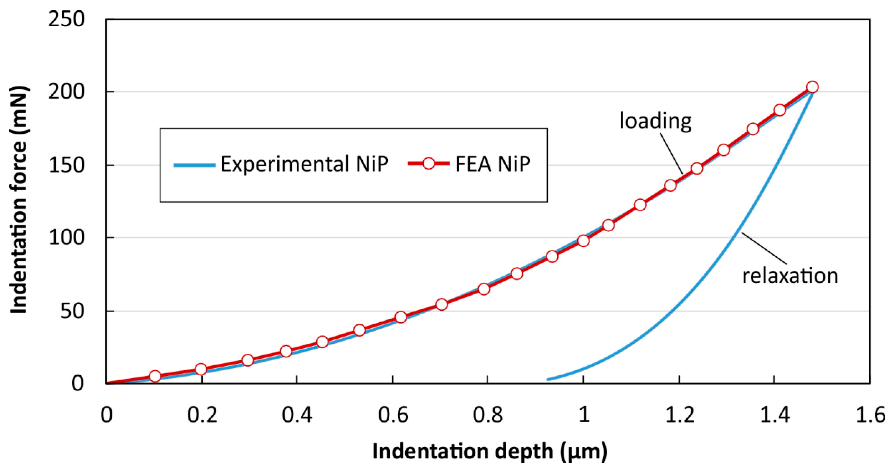
3.3. FEA-Supported Indentation Analysis

The nanoindentation test curves were fitted with the aid of a developed finite element analysis process. Contact elements were used to define the interface between the indenter and the surface of the nanocomposite coatings. The nanoindentation experiments have been computer-generated when considering two load steps. The first step simulated the loading stage of the indenter penetrating into the Ni-P nanocomposites. During the second step, the relaxation stage, the indenter was gradually removed, leading to the material elastoplastic recovery. Previous work has shown [53,54,55,58] that kinematic hardening leads to a rapid convergence in the corresponding FEM calculations, so this method was applied in the developed procedure.
During the loading stage the load-depth curve is digitized in order to generate the input for the developed computational model. Initially, the first pair of the applied force and the resulting penetration depth are processed. A first value is assumed for the first tangent modulus of the nanocomposite coating’s stress-strain curve, which corresponds to the elastic modulus. In the FEA model, a depth is applied, and then a penetration force is determined and compared to the measured value. If the FEA force does not converge to the measured one then the value of the tangent modulus is estimated again and the finite element model has to be solved once more. For the solutions with computational force matching of the experimental force, the value of the tangent modulus is considered to be accepted and the next values of force and depth are applied to the model. The next calculation step starts with the previous indentation depth, while considering the already existing stress status as well as the previously obtained tangent modulus. This process is repeated until the last couple of force-depth values has converged and the loop ends.
The results of the finite element model are demonstrated as an indentation load-depth curve, as presented in Figure 9, which displays the good correlation that was achieved between the measured indentation test and the computational curve in the case of the as-plated Ni-P coating.
The potential to calculate materials’ stress–strain curves that are based on the force-depth nanoindentation tests, for various SiC concentrations, enables the determination of coating constitutive laws through a Berkovich indenter. The corresponding stress–strain curves were determined while considering these nanoindentation results. The FEA results have revealed a precise estimate of the elasticity modulus for the neat Ni-P and Ni-P/SiC nanocomposite coatings. Table 1 demonstrates the differences between the FEA and the experimental results for all Ni-P samples. It has to be noticed that Lichinchi et al. [59] have also approached the indentation test with FEM, showing very good correlation results.
Figure 10 illustrates the FEM-extracted stress-strain laws of the Ni-P and Ni-P/SiC coatings, where higher yielding is observed for the heat-treated Ni-P/SiC coatings. When considering these results, it can be concluded that the SiC nanoparticles moderately affected the film’s mechanical properties and their stress-strain overall behavior. Furthermore, the heat treatment of the samples also improved the stress-strain behavior when compared with the as-plated Ni-P coating.

4. Conclusions

The Ni-P and Ni-P/SiC nanocomposite coatings were successfully developed based on the electrodeposition technique. XRD analysis revealed the amorphisation of samples due to P lattice incorporation in all cases of the as-deposited state and the crytallisation process and Ni3P precipitation upon heat treatment. The alteration of the surface morphology due to process parameters, SiC presence, and heat treatment were furtherly supported and examined through profilometry measurements, the results of which were in accordance with the data from SEM- and XRD analysis. Mechanical properties, such as hardness and elastic modulus, of the as-plated Ni-P and Ni-P/SiC nanocomposite coatings were investigated and compared to the same coatings after heat treatment. Nanoindentation tests were applied to measure the hardness and elastic modulus of the coatings and were used as input to FEA calculation of mechanical behavior of the coatings. A procedure is also presented to determine the nanocomposites’ stress-strain curves based on a curve-fit of nanoindentation results through a FEA simulating the indenter’s penetration into samples. The developed method takes into account the indentation results as input data to the finite element model and it determines the stress-strain curves of the Ni-P nanocomposite coatings. This FEA-supported nanoindentation technique has shown to be a very effective procedure to characterize the elastoplastic behavior of the Ni-P and Ni-P/SiC nanocomposite coatings. The estimated values of the elastic modulus while using the FEA revealed a satisfactory correlation when compared to the experimentally defined values.

Author Contributions

Data curation, K.T., D.T., A.K., G.B., D.E. and D.A.; Methodology, D.T. and C.Z.; Software, K.T.; Supervision, T.M. and D.B.

Funding

This research was funded by the European Union’s Horizon 2020 Framework Program, under topic NMP-02- 2015, project PROCETS (Grant Number: 686135).

Conflicts of Interest

The authors declare no conflict of interest. The funders had no role in the design of the study; in the collection, analyses, or interpretation of data; in the writing of the manuscript, or in the decision to publish the results.

References

  1. Sahoo, P.; Das, S.K. Tribology of electroless nickel coatings—A review. Mater. Des. 2011, 32, 1760–1775. [Google Scholar] [CrossRef]
  2. Sudagar, J.; Lian, J.; Sha, W. Electroless nickel, alloy, composite and nano coatings—A critical review. J. Alloys Compd. 2013, 571, 183–204. [Google Scholar] [CrossRef]
  3. Karthikeyan, S.; Vijayaraghavan, L. Influence of Nano Al2O3 Particles on the Adhesion, Hardness and Wear Resistance of Electroless Ni-P Coatings. Int. J. Mater. Mech. Manuf. 2016, 4, 106–110. [Google Scholar]
  4. Ankita Sharma, A.; Singh, K. Corrosion and wear study of Ni-P-PTFE-Al2O3 coating: The effect of heat treatment. Cent. Eur. J. Eng. 2014, 4, 80–89. [Google Scholar]
  5. Agarwala, R.C.; Agarwala, V. Electroless alloy/composite coatings: A review. Sadhana 2003, 28 Pt 3 & 4, 475–493. [Google Scholar] [CrossRef]
  6. Chandrasekar, M.S. Malathy Pushpavanam, Pulse and pulse reverse plating—Conceptual, advantages and applications. Electrochim. Acta 2008, 53, 3313–3322. [Google Scholar] [CrossRef]
  7. Vafaei-Makhsoos, E.; Thomas, E.L.; Toth, L.E. Electron microscopy of crystalline and amorphous Ni-P electrodeposited films: In-situ crystallization of an amorphous solid. Metall. Trans. A 1978, 9, 1449–1460. [Google Scholar] [CrossRef]
  8. Hu, C.C.; Bai, A. Influences of the phosphorus content on physicochemical properties of nickel-phosphorus deposits. Mater. Chem. Phys. 2002, 77, 215–225. [Google Scholar] [CrossRef]
  9. Breadael, E.; Blanpain, B.; Celis, J.P.; Roos, J.R. On the Amorphous and Crystalline State of Electrodeposited Nickel-Phosphorus Coatings. J. Electrochem. Soc. 1994, 141, 294–299. [Google Scholar] [CrossRef]
  10. Daly, B.P.; Barry, F.J. Electrochemical nickel–phosphorus alloy formation. Int. Mater. Rev. 2003, 48, 326–338. [Google Scholar] [CrossRef]
  11. Keong, K.G.; Sha, W.; Malinov, S. Crystallisation kinetics and phase transformation behaviour of electroless nickel–phosphorus deposits with high phosphorus content. Alloys Compd. 2002, 334, 192–199. [Google Scholar] [CrossRef]
  12. Bukaluk, A. Auger electron spectroscopy studies of interdiffusion in electrodeposited amorphous Ni-P alloys. Surf. Interface Anal. 1994, 22, 18–21. [Google Scholar] [CrossRef]
  13. Chang, L.; Kao, P.W.; Chen, C.H. Strengthening mechanisms in electrodeposited Ni–P alloys with nanocrystalline grains. Scr. Mater. 2007, 56, 713–716. [Google Scholar] [CrossRef]
  14. Bai, A.; Hu, C.C. Effects of annealing temperatures on the physicochemical properties of. nickel-phosphorous deposits. Mater. Chem. Phys. 2003, 79, 49–57. [Google Scholar] [CrossRef]
  15. Bonino, J.P.; Hotellaz, S.B.; Bories, C.; Pouderoux, P.; Rousset, A. Thermal stability of electrodeposited Ni-P alloys. J. Appl. Electrochem. 1997, 27, 1193–1197. [Google Scholar] [CrossRef]
  16. Apachitei, I.; Tichelaar, F.D.; Duszczyk, J.; Katgerman, L. The effect of heat treatment on the structure and abrasive wear resistance of autocatalytic NiP and NiP–SiC coatings. Surf. Coat. Technol. 2002, 149, 263–278. [Google Scholar] [CrossRef]
  17. Alexis, J.; Etcheverry, B.; Beguin, J.D.; Bonino, J.P. Structure, morphology and mechanical properties of electrodeposited composite coatings Ni–P/SiC. Mater. Chem. Phys. 2010, 120, 244–250. [Google Scholar] [CrossRef]
  18. Zoikis-Karathanasis, A.; Pavlatou, E.A.; Spyrellis, N. Pulse electrodeposition of Ni–P matrix composite coatings reinforced by SiC particles. J. Alloys Compd. 2010, 494, 396–403. [Google Scholar] [CrossRef]
  19. Madej, M.; Ozimina, D.; Piwonski, I. The influence of tribochemical reactions of antiwear additives on heterogeneous surface layers in boundary lubrication. Tribol. Lett. 2006, 22, 135–141. [Google Scholar] [CrossRef]
  20. Alirezaei, S.; Monirvaghefi, S.M.; Salehi, M.; Saatchi, A.; Kargosha, M. Effect of alumina content on wear behaviour of Ni–P–Al2O3 electroless composite coatings. Surf. Eng. 2005, 21, 60–66. [Google Scholar] [CrossRef]
  21. Winowlin Jappes, J.T.; Ramamoorthy, B.; Kesavan Nair, P. Novel approaches on the study of wear performance of electroless Ni–P/diamond composite deposites. J. Mater. Process. Technol. 2009, 209, 1004–1010. [Google Scholar] [CrossRef]
  22. Novaνk, M.; Vojtech, D.; Vitu, T. Influence of heat treatment on tribological properties of electroless Ni–P and Ni–P–Al2O3 coatings on Al–Si casting alloy. Appl. Surf. Sci. 2010, 256, 2956–2960. [Google Scholar] [CrossRef]
  23. Zhou, Q.; Shao, Z.; He, C.; Shao, Z.; Cai, Q.; Gao, W. Impact of surfactants on electroless deposition Ni–P–Nano-Al2O3 composite coating. J. Chin. Soc. Corros. Prot. 2007, 27, 27–30. [Google Scholar]
  24. Dong, D.; Chen, X.H.; Xiao, W.T.; Yang, G.B.; Zhang, P.Y. Preparation and properties of electroless Ni–P–SiO2 composite coatings. Appl. Surf. Sci. 2009, 255, 7051–7055. [Google Scholar] [CrossRef]
  25. Liu, T. Study on corrosive wear resistance of a Ni–P–Cr2O3 composite electroless plating with low-content phosphor in NaOH. Run Hua Yu Mi Feng 2006, 4, 90–91. [Google Scholar]
  26. Shibli, S.M.A.; Jabeera, B.; Anupama, R.I. Incorporation of nano zinc oxide for improvement of electroless nickel plating. Appl. Surf. Sci. 2006, 253, 1644–1648. [Google Scholar] [CrossRef]
  27. Sarret, M.; Muller, C.; Amell, A. Electroless Ni-P micro- and nano-composite coatings. Surf. Coat. Technol. 2006, 201, 389–395. [Google Scholar] [CrossRef]
  28. Wu, Y.; Liu, H.; Shen, B.; Liu, L.; Hu, W. The friction and wear of electroless Ni–P matrix with PTFE and/or SiC particles composite. Tribol. Int. 2006, 39, 553–559. [Google Scholar] [CrossRef]
  29. Vojtech, D. Properties of hard Ni–P–Al2O3 and Ni–P–SiC coatings on Al-aased casting alloys. Mater. Manuf. Process. 2009, 24, 754–757. [Google Scholar] [CrossRef]
  30. Araghi, A.; Paydar, M.H. Electroless deposition of Ni–P–B4C composite coating on AZ91D magnesium alloy and investigation on its wear and corrosion resistance. Mater. Des. 2010, 31, 3095–3099. [Google Scholar] [CrossRef]
  31. Hamid, Z.A.; El Badry, S.A.; Aal, A.A. Electroless deposition and characterization of Ni–P–WC composite alloys. Surf. Coat. Technol. 2007, 201, 5948–5953. [Google Scholar] [CrossRef]
  32. Wang, L.Y.; Tu, J.P.; Chen, W.X.; Wang, Y.C.; Liu, X.K.; Olk, C.; Cheng, D.H.; Zhang, X.B. Friction and wear behavior of electrodeless Ni-based CNT composite coating. Wear 2003, 254, 1289–1293. [Google Scholar] [CrossRef]
  33. Shi, Y.L.; Yang, Z.; Xu, H.; Li, M.K.; Li, H.L. Preparation of electroplated Ni-P-ultrafine diamond, Ni-P-carbon nanotubes composite coatings and their corrosion properties. J. Mater. Sci. 2004, 39, 5809–5815. [Google Scholar] [CrossRef]
  34. Petrova, M.; Noncheva, Z.; Dobreva, E. Electroless deposition of diamond powder dispersed nickel-phosphorus coatings on steel substrate. Trans. Inst. Met. Finish. 2011, 89, 89–94. [Google Scholar] [CrossRef]
  35. Matsukawa, K.; Satoh, K.; Mohri, N. Effect of wear particles on tribological properties of electroless nickel–phosphorus plating dispersed with PTFE and boron nitride. Jpn. J. Tribol. 2008, 53, 181–193. [Google Scholar]
  36. Balaraju, J.N.; Rajam, K.S. Electroless Deposition and Characterization of High Phosphorus Ni-P-Si3N4 Composite Coatings. Int. J. Electrochem. Sci. 2007, 2, 747–761. [Google Scholar]
  37. Balaraju, J.N.; Sankara Narayanan, T.S.N.; Seshadri, S.K. Electroless Ni–P composite coatings. J. Appl. Electrochem. 2003, 33, 807–816. [Google Scholar] [CrossRef]
  38. Zou, T.Z.; Tu, J.P.; Zhang, S.C.; Chen, L.M.; Wang, Q.; Zhang, L.L.; He, D.N. Friction and wear properties of electroless Ni–P–(IF–MoS2) composite coatings in humid air and vacuum. Mater. Sci. Eng. A 2006, 426, 162–168. [Google Scholar] [CrossRef]
  39. He, Y.; Wang, S.C.; Walsh, F.C.; Chiu, Y.-L.; Reed, P.A.S. Self-lubricating Ni-P-MoS2 composite coatings. Surf. Coat. Technol. 2016, 307, 926–934. [Google Scholar] [CrossRef]
  40. Ramalho, A.; Miranda, J.C. Friction and wear of electroless Ni-P and Ni-P + PTFE coatings. Wear 2005, 259, 828–834. [Google Scholar] [CrossRef]
  41. Srinivasan, K.N.; John, S. Studies on electroless nickel-PTFE composite coatings. Surf. Eng. 2005, 21, 156–160. [Google Scholar] [CrossRef]
  42. Wu, Y.; Shen, B.; Liu, L.; Hu, W. The tribological behaviour of electroless Ni–P–Gr–SiC composite. Wear 2006, 261, 201–207. [Google Scholar] [CrossRef]
  43. Wu, Y.; Liu, L.; Shen, B.; Hu, W. Study of self-lubricant Ni–P–PTFE–SiC composite coating. J. Mater. Sci. 2005, 40, 5057–5059. [Google Scholar] [CrossRef]
  44. Mansour, G.; Tzetzis, D.; Bouzakis, K.D. A nanomechanical approach on the measurement of the elastic properties of epoxy reinforced carbon nanotube nanocomposites. Tribol. Ind. 2013, 35, 190–199. [Google Scholar]
  45. Tzetzis, D.; Mansour, G.; Tsiafis, I.; Pavlidou, E. Nanoindentation Measurements of Fumed Silica Epoxy Reinforced Nanocomposites. J. Reinf. Plast. Compos. 2013, 32, 163–173. [Google Scholar] [CrossRef]
  46. Mansour, G.; Tzetzis, D. Nanomechanical characterization of hybrid multiwall carbon nanotube and fumed silica epoxy nanocomposites. Polym. Plast. Technol. Eng. 2013, 52, 1054–1062. [Google Scholar] [CrossRef]
  47. Wang, Y.; Chen, W.; Shakoor, A.; Kahraman, R.; Lu, W.; Yan, B.; Gao, W. Ni-P-TiO2 Composite Coatings on Copper Produced by Sol Enhanced Electroplating. Int. J. Electrochem. Sci. 2014, 9, 4384–4393. [Google Scholar]
  48. Alexis, J.; Gaussens, C.; Etcheverry, B.; Bonino, J.P. Development of nickel phosphorus coatings containing micro particles of talc phyllosilicates. Mater. Chem. Phys. 2013, 137, 723–733. [Google Scholar] [CrossRef]
  49. Wang, Q.; Callisti, M.; Miranda, A.; McKay, B.; Deligkiozi, I.; Milickovic, T.K.; Zoikis-Karathanasis, A.; Hrissagis, K.; Magagnin, L.; Polcar, T. Evolution of structural, mechanical and tribological properties of Ni–P/MWCNT coatings as a function of annealing temperature. Surf. Coat. Technol. 2016. [Google Scholar] [CrossRef]
  50. Birlik, I.; Azem, A.; Funda, N.; Toparli, M.; Celik, E.; Koc Delice, T.; Yildirim, S.; Bardakcioglu, O.; Dikici, T. Preparation and characterization of ni–TiO2 nanocomposite coatings Produced by electrodeposition Technique. Front. Mater. 2016, 3, 46. [Google Scholar] [CrossRef]
  51. Tien, S.K.; Duh, J.G.; Chen, Y.I. The influence of thermal treatment on the microstructure and hardness in electroless Ni-P-W deposit. Thin Solid Films 2004, 469, 333–338. [Google Scholar] [CrossRef]
  52. Islam, M.; Azhar, M.R.; Khalid, Y.; Khan, R.; Abdo, H.S.; Dar, M.A.; Oloyede, O.R.; Burleigh, T.D. Electroless Ni-P/SiC Nanocomposite Coatings With Small Amounts of SiC Nanoparticles for Superior Corrosion Resistance and Hardness. J. Mater. Eng. Perform. 2015, 24, 4835–4843. [Google Scholar] [CrossRef]
  53. Tzetzis, D.; Tsongas, K.; Mansour, G. Determination of the Mechanical Properties of Epoxy Silica Nanocomposites through FEA-Supported Evaluation of Ball Indentation Test Results. Mater. Res. 2017, 20, 1571–1578. [Google Scholar] [CrossRef] [Green Version]
  54. Mansour, M.; Tsongas, K.; Tzetzis, D.; Antoniadis, A. Mechanical and dynamic behavior of fused filament fabrication 3D printed polyethylene terephthalate glycol reinforced with carbon fibers. Polym.-Plast. Technol. Eng. 2018, 57, 1715–1725. [Google Scholar] [CrossRef]
  55. Mansour, M.; Tsongas, K.; Tzetzis, D. Measurement of the mechanical and dynamic properties of 3D printed polylactic acid reinforced with graphene. Polym.-Plast. Technol. Eng. 2019, 58, 1234–1244. [Google Scholar] [CrossRef]
  56. Oliver, W.C.; Pharr, G.M. An Improved Technique for Determining Hardness and Elastic-Modulus using Load and Displacement Sensing Indentation Experiments. J. Mater. Res. 1992, 7, 1564–1583. [Google Scholar] [CrossRef]
  57. Nava, D.; Dávalos, C.E.; Martínez-Hernández, A.; Manríquez, F.; Meas, Y.; Ortega-Borges, R.; Pérez-Bueno, J.J.; Trejo, G. Effects of heat treatment on the tribological and corrosion properties of electrodeposited Ni-Palloys. Int. J. Electrochem. Sci. 2013, 8, 2670–2681. [Google Scholar]
  58. Bouzakis, K.D.; Michailidis, N.; Erkens, G. Thin hard coatings stress strain curve determination through a FEM supported evaluation of nanoindentation test results. Surf. Coat. Technol. 2001, 142–144, 102–109. [Google Scholar] [CrossRef]
  59. Lichinchi, M.; Lenardi, C.; Haupt, J.; Vitali, R. Simulation of Berkovich nanoindentation experiments on thin films using finite element method. Thin Solid Films 1998, 312, 240–248. [Google Scholar] [CrossRef] [Green Version]
Figure 1. Schematic of nanoindentation load-depth curve of an elastoplastic material, where hmax is the maximum depth, he is the elastic depth rebound, hr is the residual impression depth, ha is the displacement of the surface at the perimeter, and hf is the contact indentation depth.
Applsci 09 02901 g001
Figure 2. Scanning electron microscope pictures the different electrodeposited coating systems produced at 50% duty cycle, 100 Hz with and without heat treatment (HT) at 400 °C.
Applsci 09 02901 g002
Figure 3. X-ray diffraction (XRD) spectra of the plain and SiC reinforced coatings developed at 50% duty cycle at 100 Hz prior to heat treatment.
Applsci 09 02901 g003
Figure 4. XRD spectra of the plain and SiC reinforced coatings developed at 50% duty cycle at 100 Hz after heat treatment.
Applsci 09 02901 g004
Figure 5. Average surface roughness and root mean square (RMS) roughness of the produced coatings.
Applsci 09 02901 g005
Figure 6. Typical two-dimensional (2D) and three-dimensional (3D) surface reconstructions for (a) non treated Ni-P/SiC and (b) heat treated Ni-P/SiC coatings.
Applsci 09 02901 g006
Figure 7. Nanoindentation load–depth curves of as-plated Ni-P, Ni-P/SiC nanocomposites, and the heat treated coatings.
Applsci 09 02901 g007
Figure 8. Calculated (a) hardness and (b) elastic modulus of as-plated Ni-P, Ni-P/SiC nanocomposites, and the heat treated coatings.
Applsci 09 02901 g008
Figure 9. Comparison between FEA-determined and experimental nanoindentation tests.
Applsci 09 02901 g009
Figure 10. Analytical-experimental determined stress-strain curves of Ni-P and Ni-P/SiC nanocomposite coatings.
Applsci 09 02901 g010
Table 1. Comparison of the elastic moduli of the nanocomposite coatings calculated from nanoindentation experiments and Finite Element Analysis (FEA) determined estimates.
SpecimenElastic Modulus [GPa]
Nanoindentation TestFEA
Ni-P7076
Ni-P HT95100
Ni-P/SiC114120
Ni-P/SiC HT125140

