1. Introduction
With the penetration rate of wind power in micro-grid increasing, the indeterminacy and volatility of wind power generation will directly affect the balance of supply and demand of active power in the micro-grid system, causing frequency fluctuations. Countries around the world have introduced grid codes, which stipulate that wind farms must be able to regulate active power and provide frequency support [
1,
2].
At present, the most widely used kind of wind turbines (WTs) is a double-fed induction generator (DFIG), which is connected to the grid through power electronic devices, thus is unable to respond to system frequency deviations without supplementary active power control methods, which includes rotor speed control, pitch angle control, and their combination. In Ref. [
3], only pitch angle control is applied in the frequency regulation (FR) by DFIG, while the potential of rotor speed control is not exploited. However, the power regulation through rotor speed control is faster than pitch angle control, so its FR performance is better. The combination of two control methods is adopted in the FR strategy presented by Ref. [
4], but the de-loading of DFIG is not studied; thus, DFIG can only participate in down-regulation. Only DFIG in the de-loading state can participate in both system up-regulation and down-regulation.
Constrained by operation limit of DFIG, the de-loading strategy for different wind speed (WS) region is different, and the combination of rotor speed and pitch angle control is commonly applied in the researches about DFIG de-loading. In the DFIG de-loading strategy of Ref. [
5], the dividing of WS regions is proposed based on the operation characteristic of DFIG. However, the dividing method does not designate the starting point of low WS region; thus, the FR reserve capacity cannot reach the expected value due to the lower limit of rotor speed. In addition, the pitch angle control is only applied in high WS region, which will result in the lack of reserve capacity in median WS region due to the upper limit of rotor speed. In both reference. [
6] and reference [
7], the dividing of WS regions is used for appointing different de-loading mode or FR type to WTs under different WS in the wind power plant, which does not consider the smooth transition between control methods. In other words, most existing researches ignored the continuous change of rotor speed or pitch angle at the junctions of different WS regions and the probability of not reaching expected FR reserve capacity in each WS region. Therefore, it is necessary to establish a DFIG FR model, which is applicable under continuously varying WS in whole WS range.
However, WTs underperform in providing FR service due to the volatility and indeterminacy of wind power. Therefore, it is difficult for WT to provide frequency support independently. The energy storage system is often used to assist renewable energy generation to provide auxiliary services [
8]. The coordinated control strategy in Ref. [
9] uses battery energy storage system (BESS) as a secondary energy resource to assist wind power plant to provide FR service for long-term operation. In Ref. [
10], the proposed cooperation strategy employs wind power to track the FR signal in priority and battery storage to compensate for insufficient and inaccurate power. Nevertheless, the auxiliary energy storage system requires a large amount of additional equipment, which will greatly increase the operation cost of the wind farm. Meanwhile, the method only improves the frequency response on the power supply side but does not exploit the potential of the load side in system FR.
The quantity of electric vehicle (EV) will increase significantly in the future because the development of EV is attached great importance by countries around the world in consideration of the global environmental pollution and energy shortage crisis. Through proper price guidance, EV cluster can provide reserve capacity for FR. As a kind of existing energy storage resources, electric vehicle (EV) can take the place of additional energy storage equipment in assisting WT to participate in FR without extra cost, as well as improve system frequency response on both load and source side at the same time owing to its dual role. In Ref. [
11], a charging and discharging control strategy for EV cluster to participate in secondary FR of a two-area interconnected system containing WTs is put forward. An optimal charging/discharging scheduling strategy of EVs is proposed in [
12] to improving the frequency stability of micro-grid with penetration of wind power. However, instead of being one of the FR participators, wind power model is only taken as random disturbance of power generation considering its intermittent characteristics in these mentioned researches, which will increase the pressure of system FR.
Therefore, under the background of large-scale wind power integration, it is necessary to appoint a part of WTs in the grid as auxiliary frequency regulation units, sharing FR pressure with EV so as to stabilize system frequency. In Ref. [
13], the coordination of EV cluster and WT in system FR is realized by hierarchical control algorithm, in which EV cluster participate in FR in the lower layer, while WT only participates in generation dispatching plan in the upper layer. The coordinated control strategy of WT’s pitch angle and EV based on model predictive control is proposed in Ref. [
3] for micro-grid FR, but the control imposed on WTs is used for smoothing its power output, so only EV cluster responds to the frequency deviation signal. Two coordinated FR methods for EV and WT based on centralized and distributed control, respectively, are analyzed in Ref. [
14], but in the proposed control structures, EV and WT output power for FR separately without the allocation of demand active power between them, which means that the FR tasks of EV and DFIG are not coupled with each other, which may cause the system to demand power that cannot be effectively fulfilled or the waste of power output. Moreover, in the most relevant researches, the influence of FR reserve capacity of DFIG or EV on the power output limit is not considered. Therefore, it is necessary to study the allocation method of system FR task considering the FR capacity so as to achieve the mutually coupled coordination of DFIG and EV in FR.
For the sake of solving the problems mentioned above, the main contributions of the paper are listed as follows:
Through reasonable dividing of WS regions and operation point selection of pitch angle, a modified de-loading strategy of DFIG for FR reserve capacity is proposed, which realizes the continuous change of rotor speed or pitch angle and guarantees expected FR capacity in every WS zone.
Combining rotor speed and pitch angle control, the FR model of DFIG for both up-regulation and down-regulation under continuously varying WS in whole WS range is established.
In the premise of meeting the driving demand of EV owners, based on the real-time allocation strategy of system FR task considering the real-time predicted FR capacity of DFIG and EV cluster, the coordinated control strategy of DFIG and EV in system secondary FR is presented.
The remainder of the paper is organized as follows.
Section 2 presents the de-loading strategy and FR model of DFIG based on the combination of rotor speed and pitch angle control. Then,
Section 3 elaborates the FR control strategy of EV cluster considering the driving demand of vehicle owners. The coordinated FR strategy of EV and DFIG based on the real-time allocation of system FR task is described in
Section 4. The analysis of simulation results is shown in
Section 5. Finally, conclusions are drawn in
Section 6.
2. Frequency Regulation Model of DFIG
2.1. Power Output Control Principle of DFIG
By controlling the pitch angle and the converters on both sides of rotor and grid, the mechanical power output of wind turbine can be regulated through various controllers [
15,
16], as shown in (1):
where
is the active power output of DFIG, which equals to the mechanical power captured by DFIG while the loss of gearbox and transmission system is ignored;
is the air density, whose value is 1.225 kg/m
3;
R is the blade radius of DFIG;
is the wind speed;
is the blade power coefficient of DFIG, whose value is related to the pitch angle
and the tip-speed ratio
;
are relevant parameters of DFIG characteristics [
4], whose value are 0.22, 116, 0.4, 5, 12.5, 0.08, and 0.035, respectively;
is the angular velocity of blade, whose value is proportional to the rotor speed
, as shown in (2):
where
n is the gearbox transmission ratio of DFIG, whose value is constant for a fixed WT model.
From Equations (1) and (2), it can be derived that
changes with wind speed
, rotor speed
, and pitch angle
, which can be expressed as
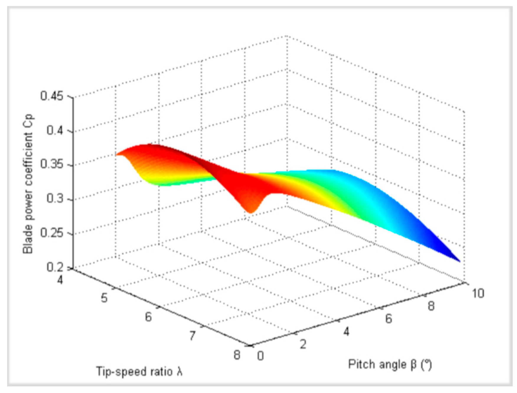
. Therefore, in the situation of fixed WS, the active power output of DFIG can be regulated through controlling the rotor speed and pitch angle. In this way, DFIG will be able to participate in system FR. As can be derived from (1), DFIG blade power coefficient
changes with
and
, and
Figure 1 shows the change rule of
. It can be seen that when pitch angle
, there is an optimal tip-speed ratio
corresponding to the maximum blade power coefficient
, which can be reached by regulating the rotor speed to be the optimal rotor speed
. Moreover, the DFIG power output can be reduced by increasing the pitch angle to a certain extent.
2.2. De-Loading Strategy for FR Reserve Capacity
2.2.1. Normal Operation of DFIG
For the normal operation of DFIG, in order to improve the power output efficiency of WT, the maximum power point tracking (MPPT) control strategy is adopted to achieve maximum capture of wind energy [
17]. The rotor speed of the DFIG normally operates in the range of 0.7–1.2 p.u., and the safety range can reach 0.6–1.3 p.u. under transient dynamic disturbances [
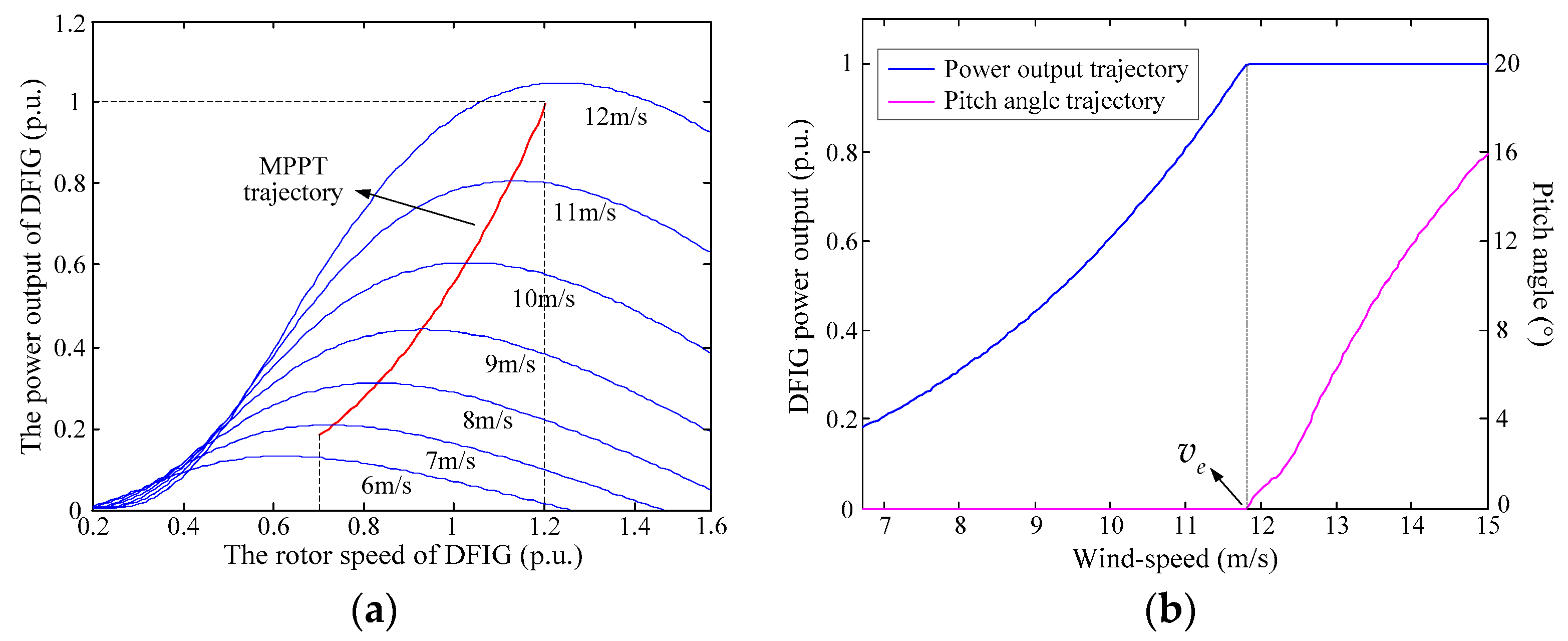
5]. In the MPPT state, the rotor speed of DFIG is adjusted dynamically to be the optimal rotor speed
, so as to achieve the maximum power output
under different WSs, as shown in
Figure 2a. If the maximum power reaches the rated power
, the corresponding optimal speed
will go beyond the normal operation range; thus, the pitch angle will be increased to constrain rotor speed within its limit, keeping DFIG’s power output at the rated power, as shown in
Figure 2b, where
is the rated WS corresponding to
.
2.2.2. Division of Wind Speed Region
For participating in down-regulation, the DFIG can reduce the power output directly through controlling rotor speed or pitch angle. However, DFIG cannot participate in up-regulation when operating in MPPT state since the power output has already reached the maximum value. In order to obtain up-regulation reserve capacity, the DFIG needs to operate in a de-loading state. In order to realize the de-loading of DFIG, the rotor speed needs to deviate from the optimal speed. The suboptimal operation state of rotor corresponds to two rotor speeds under the same WS, i.e., the low-speed and over-speed suboptimal rotor speed. In the actual situation, the over-speed suboptimal trajectory is usually adopted in order to maintain DFIG’s stable operation.
However, in consideration of the operation limit of rotor speed, the de-loading level may not be satisfied if the power output regulation is only based on rotor speed control. In this situation, the pitch angle control will be activated to keep DFIG power output at a designated de-loading level. In order to realize the smooth transition between rotor speed control, pitch angle control, and their combination in the de-loading strategy, reasonable division of the WS region according to the operation characteristic of DFIG is important.
The whole WS range is divided into three regions considering the operation characteristic of DFIG, including the start-up region, the FR region, and the cut-out region. In the start-up region, the power output of DFIG is too low for providing frequency support; in the cut-out region, the DFIG will exit the grid as the WS is too high. Therefore, the DFIG will only participate in FR in the FR region. Further, considering the operation limit of DFIG, the FR region should be divided into three regions, that is, the low, medium, and high WS region. The division principle of WS regions is elaborated below.
Firstly, in order to ensure that the up-regulation capacity can be fully obtained, the WS at the lower boundary of low WS region should meet the requirement that the maximum point of DFIG power output can be reached when the rotor speed is at the lower limit. Secondly, when suboptimal rotor speed corresponding to designated de-loading level has reached the upper limit, the WS will be set as the boundary of low and median WS region, and it is where the pitch angle control will start to work. Then, the rated WS is set as the boundary of median and high WS region, where the upper limit of rotor speed equals to the optimal speed; thus, only pitch angle control will work on the de-loading in high WS region. Finally, the cut-out speed of DFIG
is set as the higher boundary of high WS region. The division principle and corresponding calculated values are shown in
Table 1, where
is the de-loading rate, which is set to be 10% in this paper [
5] and can be adjusted according to the actual situation.
2.2.3. Operation Point Selection of Pitch Angle
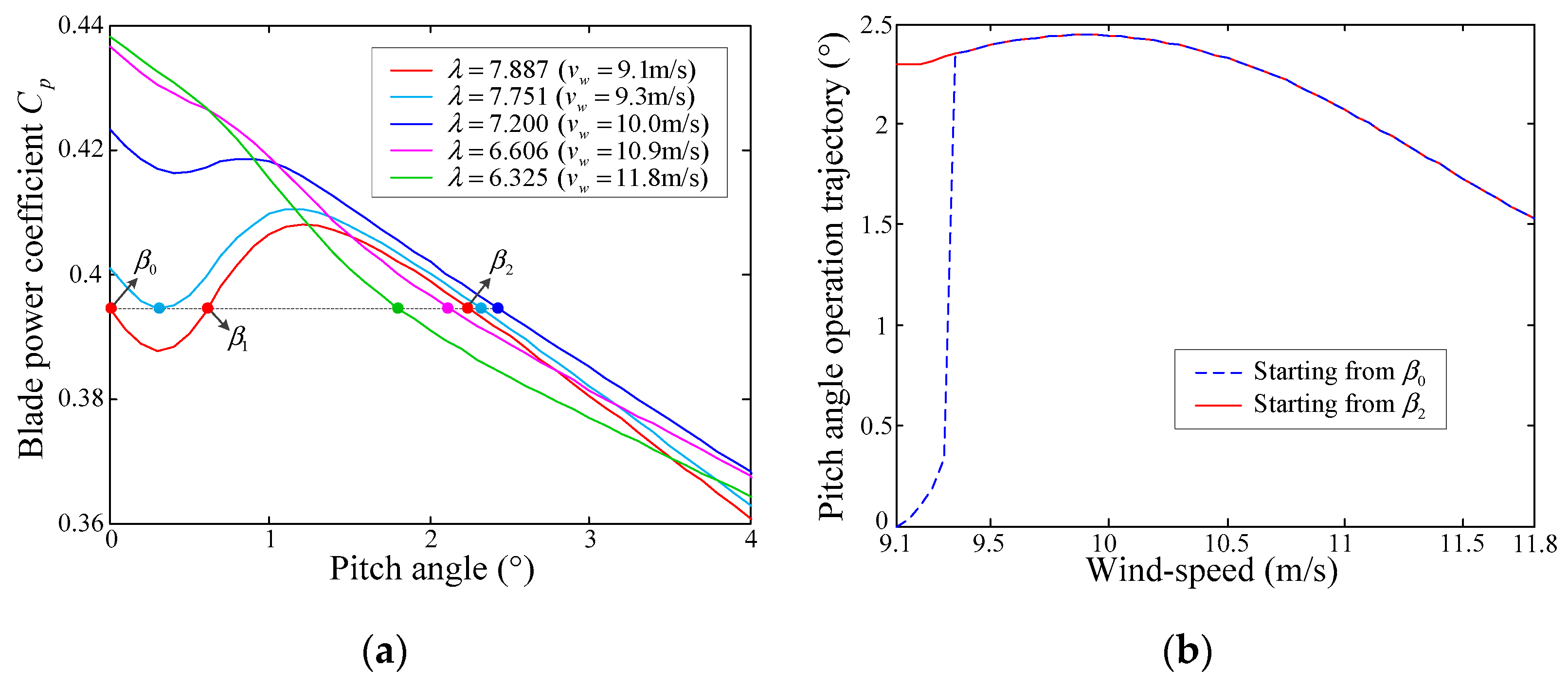
It is noteworthy that the pitch angle control starts to work at the boundary of low and median WS regions, but the DFIG power output does not increase monotonically with pitch angle here, as shown in
Figure 3a, where the current rotor speed keeps at 1.2 p.u. At the boundary WS (9.1 m/s), there are three pitch angle values (
) that can keep the blade power coefficient
to be the value corresponding to
, that is,
. It can be seen that when
decreases with the increase in WS in medium WS region, the change rule of
with pitch angle is gradually changing from non-monotonic to monotonic. In order to keep the power output at
, the pitch angle will be adjusted to keep
at
. However, if
is chosen as the initial operation point of pitch angle in medium WS region, the pitch angle will jump near 9.3 m/s due to the change in variation trend of
, as shown in
Figure 3b.
On the one hand, the frequent adjustment of pitch angle is not recommended considering the life-span and maintenance cost of WT [
7]; on the other hand, when the time interval of FR order is small, the pitch angle may not be able to achieve the target value as a result of change in rate limit. Therefore, for the sake of avoiding the sharp change in pitch angle,
is chosen as the initial operation point of pitch angle control in medium WS region. Moreover, in low WS region,
always keep at 7.887 through the adjustment of rotor speed; thus, the profile of
is the same as 9.1 m/s. In order to avoid the jump of pitch angle at the boundary of low and medium WS regions, the pitch angle should keep operating at
in low WS region, which can achieve the same power output as
, i.e., 0°.
2.2.4. De-Loading Strategy of DFIG
Based on the division of the WS region and operation point selection of pitch angle, the specific de-loading strategy of DFIG in different WS regions are elaborated below.
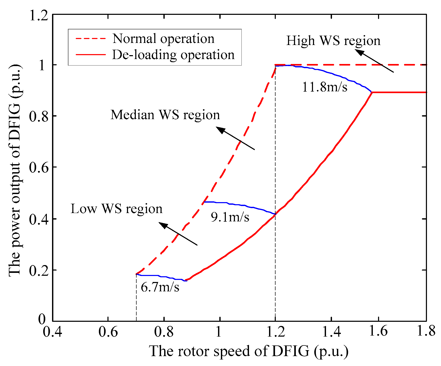
Low WS region: The DFIG outputs 90% maximum power by controlling the rotor speed to operate at the over-speed suboptimal trajectory, providing reserve capacity of 10% maximum power for up-regulation. The pitch angle remains at .
Medium WS region: The rotor speed cannot follow the over-speed suboptimal trajectory due to the upper limit of 1.2 p.u.; thus, the pitch angle is increased to keep 90% maximum power output, providing reserve capacity of 10% maximum power for up-regulation. The rotor speed remains at 1.2 p.u.
High WS region: The maximum power point has reached the rated power. The DFIG outputs 90% rated power by controlling the pitch angle, providing reserve capacity of 10% rated power for up-regulation. The rotor speed remains at 1.2 p.u.
In the de-loading strategy, the rotor speed and pitch angle operation strategy for providing FR reserve capacity is summed up in (3) and (4), respectively:
where
and
are the operating rotor speed and a pitch angle of DFIG for providing FR capacity, respectively. In addition, the operation range of the pitch angle is 0–70° [
5].
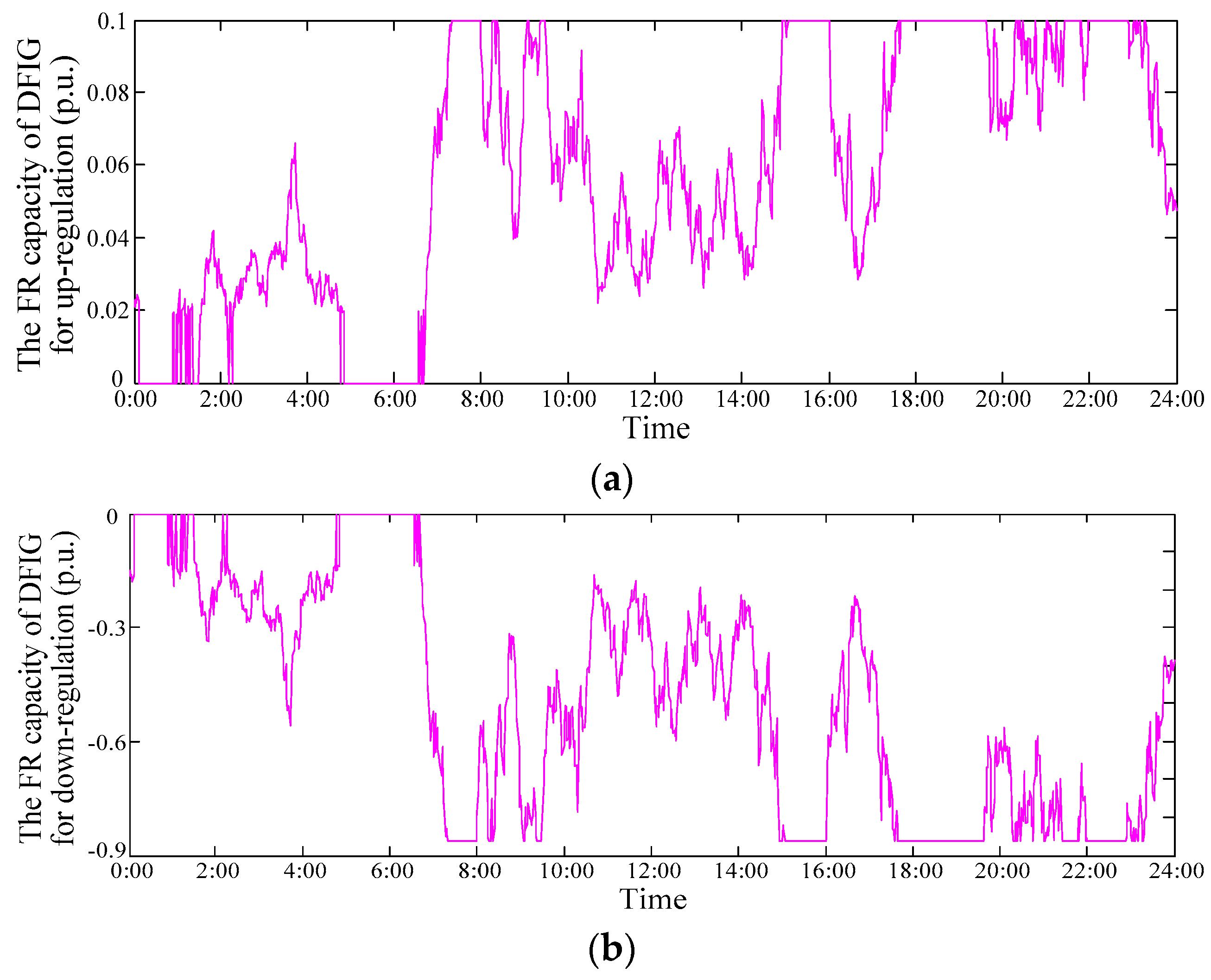
Therefore, through real-time measured wind speed, the FR reserve capacity of DFIG for up-regulation and down-regulation can be predicted in real-time by (5) and (6), respectively:
where
is the lower limit of DFIG’s power output for grid integration, whose value equals the maximum power at cut-in speed. If the power output is lower than
, DFIG’s mechanical power cannot maintain the power balance, thus, is unable to participate in FR. Moreover,
is set to be positive, and
is set to be negative in this paper.
The de-loading operation trajectory of DFIG power output is shown in
Figure 4.
2.3. FR Model of DFIG in Whole WS Range
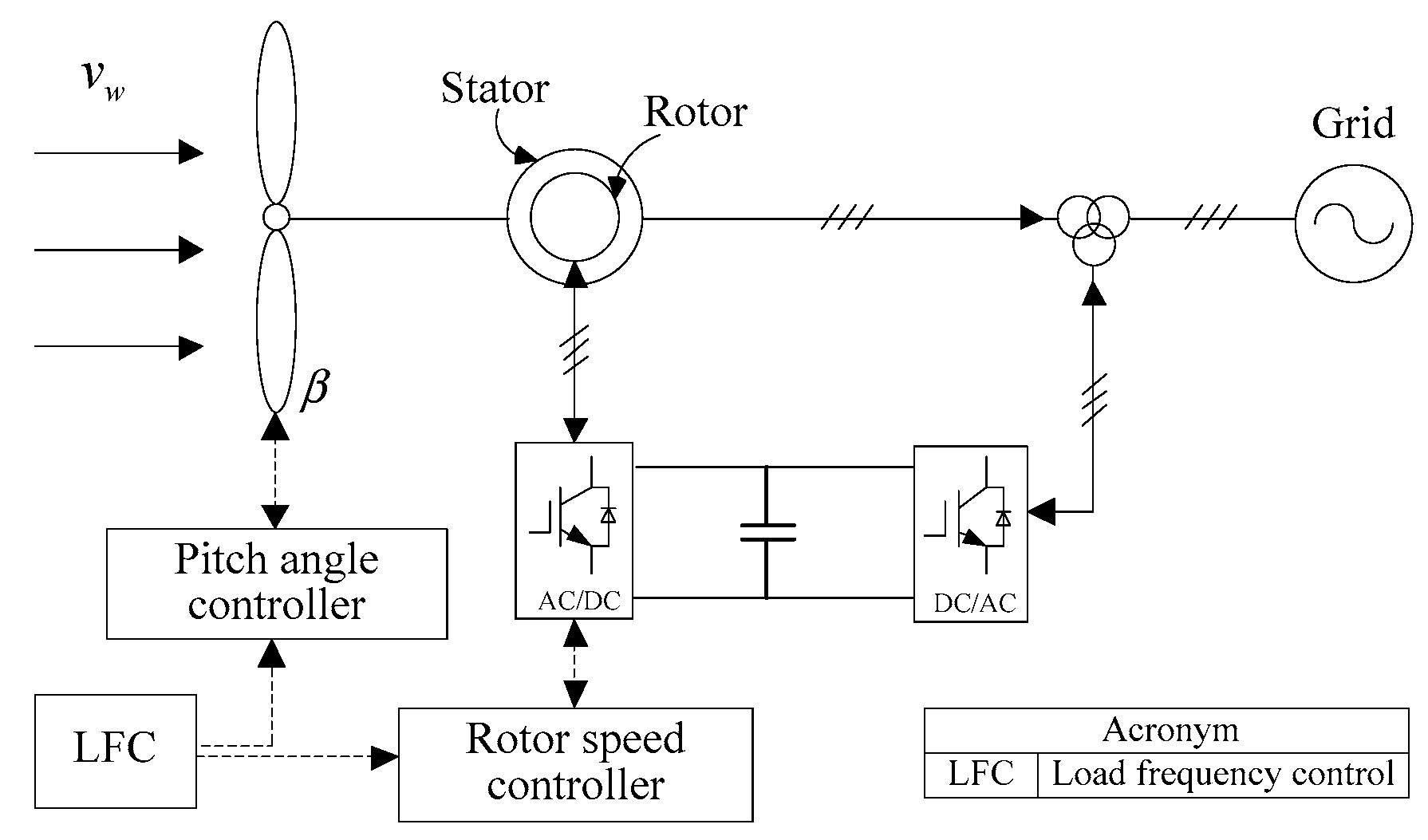
Based on the combination of rotor speed and pitch angle control, an FR control model is established for DFIG to participate in system frequency up-regulation and down-regulation. When the system frequency fluctuates, the active power output of DFIG is regulated by controlling rotor speed
, pitch angle
, or both according to the current WS region. The FR control principle block diagram of DFIG is shown in
Figure 5. The active power adjustment through rotor speed control is realized by controlling the active component of rotor current; thus, it can respond to the system frequency change in a relatively fast manner. While the pitch angle control is implemented by controlling the mechanical components of the pitch angle controller, which is much slower [
7]. Therefore, the rotor speed control is always given priority in the participation of FR.
Based on the operation characteristic and de-loading strategy of DFIG, the FR control methods applied in different WS regions are shown in
Table 2. The procedures of DFIG participating in FR in the three WS regions are elaborated below.
Low WS region:
Up-regulation: The DFIG reduces so as to increase power output. When reaches , if the FR task allocated to DFIG by grid control center still cannot be fulfilled, the deceleration should be stopped. Then, will be reduced to continue increasing power output. If the FR task still cannot be fulfilled even when reaches , stops decreasing and DFIG stays in the MPPT state, providing frequency support in another way.
Down-regulation: The DFIG raises so as to decrease power output. If the FR task cannot be fulfilled even when reaches 1.2 p.u., the acceleration should be stopped. Then, will be raised to continue decreasing power output. If the FR task still cannot be fulfilled even when reaches or the power output reaches , stops increasing, providing frequency support in another way.
Medium WS region:
Up-regulation: The DFIG reduces so as to increase power output. If the FR task still cannot be fulfilled even when reaches , the deceleration should be stopped. Then, will be reduced to continue increasing power output. If the FR task still cannot be fulfilled even when reaches , stops decreasing and DFIG stays in the MPPT state, providing frequency support in another way.
Down-regulation: The DFIG raises so as to decrease power output. If the FR task cannot be fulfilled even when reaches or the power output reaches , stops increasing, providing frequency support in another way. always remains at 1.2 p.u.
High WS region:
Up-regulation: The DFIG reduces so as to increase power output. If the FR task cannot be fulfilled even when the power output reaches , stops decreasing, providing frequency support in another way. always remains at 1.2 p.u.
Down-regulation: The DFIG raises so as to decrease power output. If the FR task cannot be fulfilled even when reaches or the power output reaches , stops increasing, providing frequency support in another way. always remains at 1.2 p.u.
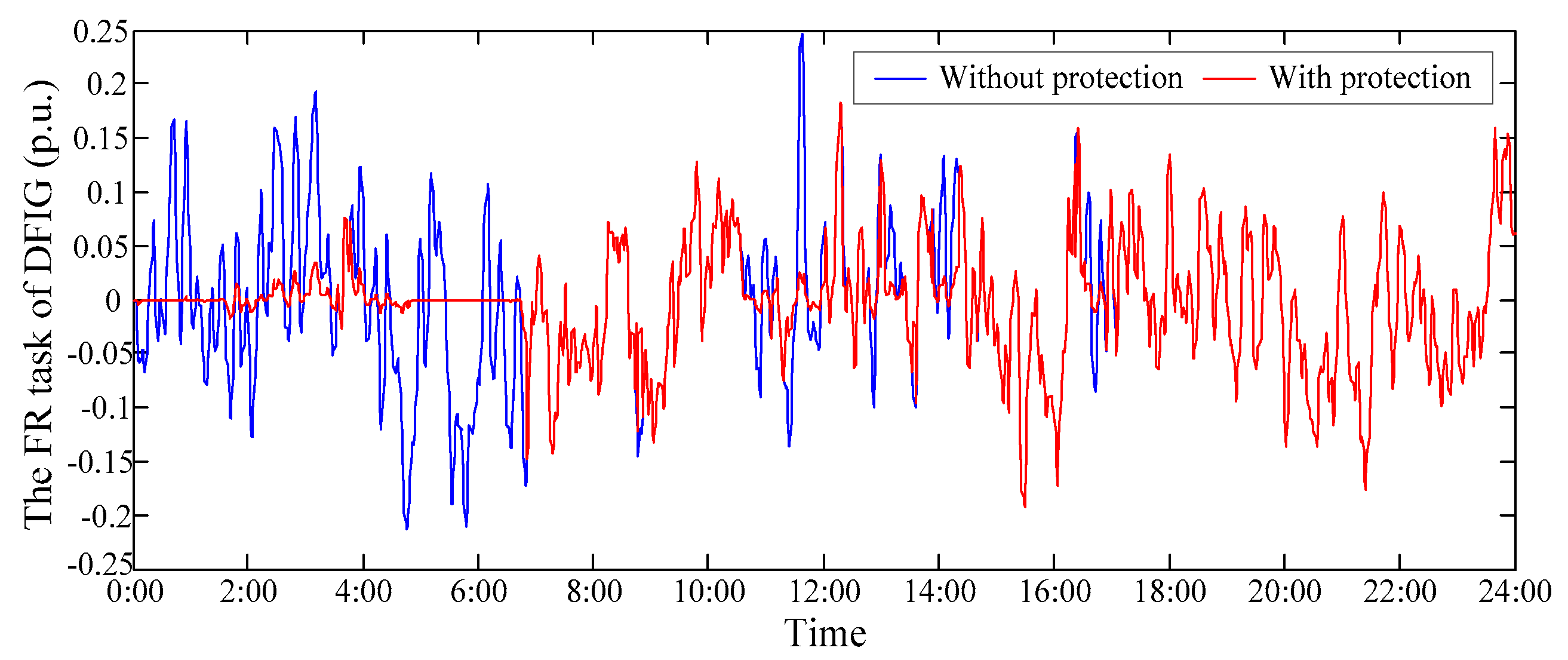
2.4. Rotor Speed Protection
In the process of DFIG participating in FR, especially in the low WS region, the excessively large rotor speed drop may cause the DFIG to be unstable or stalled [
12]. Therefore, the rotor speed protection is usually introduced to make the DFIG directly exit FR when the rotor speed reaches the lower limit (0.7 p.u.). However, the protection method, with fixed limit value, does not consider the influence of the external WS condition, and DFIG directly exiting FR is also likely to cause a secondary deviation of the system frequency.
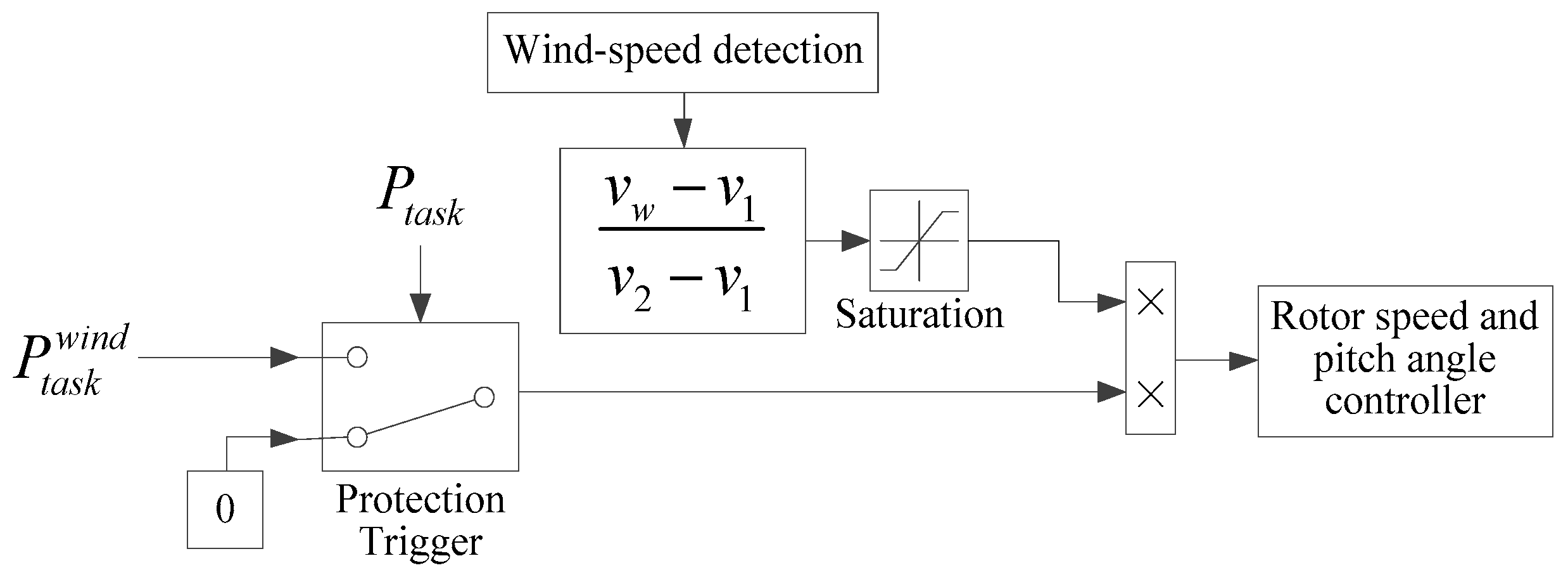
Therefore, a rotor speed protection block is added before the DFIG controller in this paper, as shown in
Figure 6, where
. The principle of the protection block is that the FR task of DFIG is gradually reduced with the decrease in WS in low WS region so that the DFIG gradually exits FR with the decrease in rotor speed. The input signal of protection trigger is the system FR task, which ensures the synchronous action of rotor speed protection and DFIG’s participation in FR. The function of saturation block is set to make the output equal to zero when the input is negative, so the FR task of DFIG will become zero when the WS is below 6.7 m/s, which means that DFIG is totally exiting FR. In this way, the stability of the wind turbine during the FR process is maintained, and the system frequency is prevented from secondary deviation.
In conclusion, based on the de-loading strategy for FR capacity, considering rotor speed control, the secondary FR model for DFIG to participate in both system frequency up-regulation and down-regulation in whole WS range is established through the combination of rotor speed and pitch angle control.
4. The Coordinated FR Strategy of DFIG and EV
In order to improve the reliability of frequency support provided by DFIGs, considering the frequency stability improvement from load side, EV is used as an auxiliary energy storage system to coordinate with DFIG to participate in system FR.
4.1. Real-Time Allocation of System FR Task
In order to realize the coordination of DFIG and EVA in system FR, a real-time allocation strategy of system FR task is proposed. The de-loading operation will influence the economic efficiency of DFIG [
4]. Therefore, taking into account the economical operation of the wind farm, the DFIG is set to have priority over EV in up-regulation. Meanwhile, when the EV is connected to the grid, charging is the first demand for EV owner. In order to reduce EV’s charging load for driving demand, the EVA is set to have priority over DFIG in down-regulation.
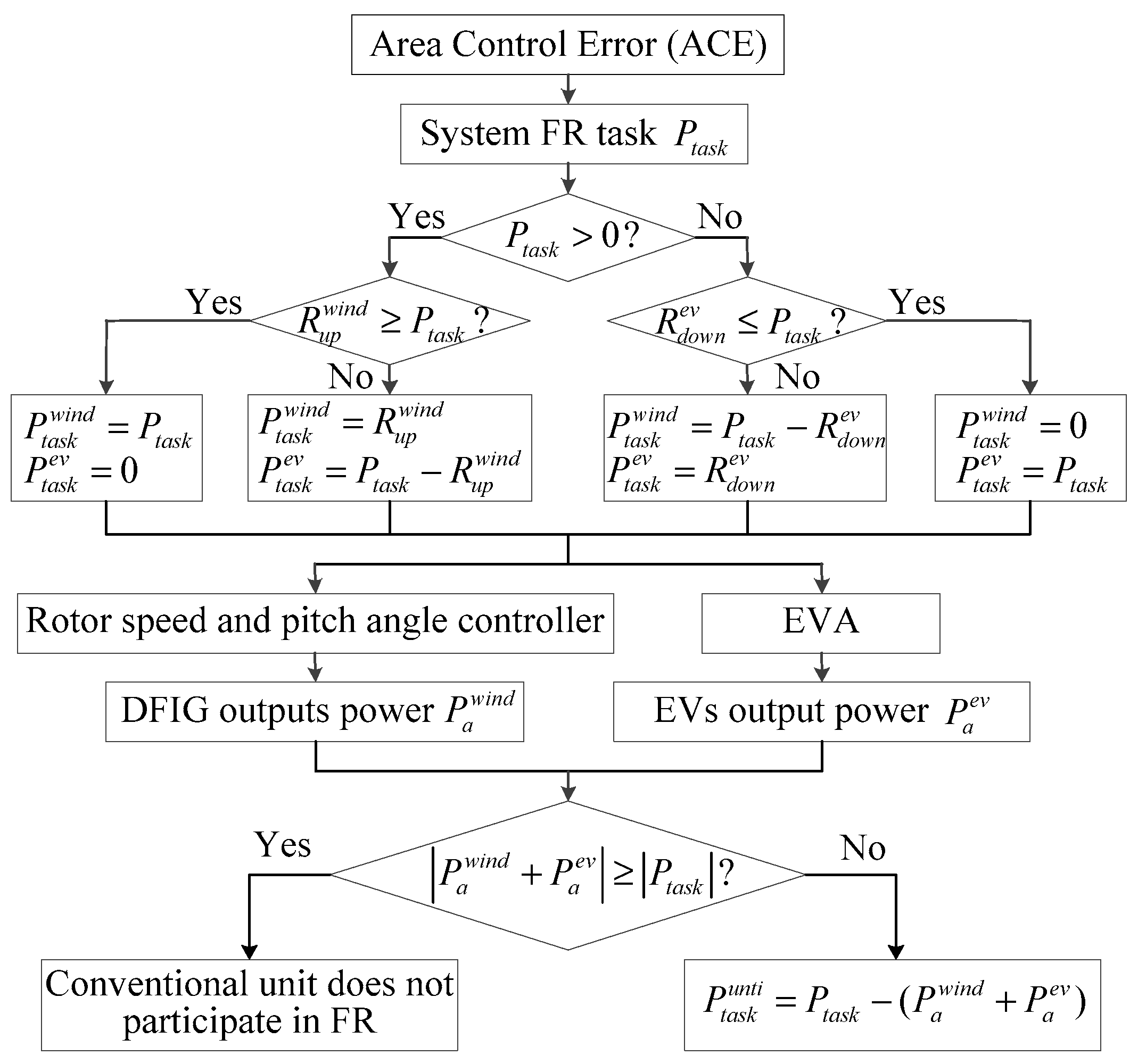
When the system frequency fluctuates, the system FR task will be allocated to DFIG and EVA according to the FR capacity and the type of FR, which includes five modes, as elaborated below. is set to be positive for up-regulation and negative for down-regulation.
Mode 1: If
, the system FR task
will be allocated to DFIG first. If the up-regulation capacity of DFIG is more than the system FR task, i.e.,
, all the FR power output will be provided by DFIG, while EVA will not participate in FR. Thus, the FR tasks of DFIG and EVA are shown in (16):
where
and
are the FR tasks allocated to DFIG and EVA, respectively.
Mode 2: If
,
will be allocated to DFIG first. If
, the DFIG cannot accomplish the system FR task alone, so the shortage will be allocated to EVA. Thus, the FR tasks of DFIG and EVA are shown in (17):
Mode 3: If
,
will be allocated to EVA first. If the up-regulation capacity of EVA is more than the system FR task, i.e.,
, all the FR power output will be provided by EVA, while the DFIG will not participate in FR. Thus, the FR tasks of DFIG and EVA are shown in (18):
Mode 4: If
,
will be allocated to EVA first. If
, the EVA cannot accomplish the system FR task alone, so the shortage will be allocated to DFIG. Thus, the FR tasks of DFIG and EVA are shown in (19):
Mode 5: If
, DFIG and EVA will not participate in FR. Thus, the FR tasks of DFIG and EVA are shown in (20):
4.2. The Procedure of Coordinated FR Strategy
The detailed procedure of DFIG and EVA coordinating to participate in system secondary FR are shown below.
Step 1: According to the WS environment, whether the DFIG can be connected to the grid safely or not will be confirmed. If the security of the DFIG connection can be ensured, the current WS region is determined by the WS, and then the DFIG is controlled to operate in the corresponding de-loading state. At the same time, EVs are connected to the grid according to daily driving rules. Under the dispatch of EVA, EVs in the grid are divided into discharging group, charging group, and energy demand group; then, EV’s controllable energy for up-regulation and down-regulation can be calculated in real time.
Step 2: Considering the FR capacity and the type of FR, the system FR task will be allocated to DFIG and EVA according to the proposed real-time allocation strategy.
Step 3: Following the FR task allocated by the control center, both the DFIG and EVA output power to participate in FR.
DFIG: Based on the allocated FR task, the DFIG starts to output power by following the commands from the rotor speed and pitch angle controller. When is accomplished, DFIG stops regulating rotor speed and pitch angle, and the actual power output of DFIG is . If has not been accomplished when the rotor speed, pitch angle, or output power has reached the operation limit, the DFIG stops regulating its operation state and remains at current power output .
EVA: Based on the allocated FR task, the EVA instructs the EVs inside the cluster to participate in FR. If the FR capacity of EVA is larger than the FR task of EVA, i.e., , EVs in the FR service group will be sorted by the credibility of each EV, and then the EV with a lower credibility will be given higher priority to output power for FR until the FR task is accomplished; if , all the EVs in the FR service group will output power for FR at the same time. The actual power output of EVA is .
Step 4: If the system FR task can be accomplished by the actual FR power output of DFIG and EVA, i.e.,
, the conventional unit will not participate in FR. If the actual FR power output of DFIG and EVA cannot fulfill the system FR task, i.e.,
, the shortage will be compensated by the power output of a conventional unit. The FR task allocated to the conventional unit is shown in (21):
Then, considering the limitation of ramp rate, the conventional unit output power according to the allocated FR task.
In summary, the flow chart of DFIG and EVA coordinating to participate in system FR is shown in
Figure 7, where the up-regulation and down-regulation capacity are set to be positive and negative, respectively, for both EVA and DFIG.


