1. Introduction
Controllable and robust robotic gripping and manipulation technologies play a significant role in manufacturing automation applications [
1]. These technologies are usually classified into four categories: (1) impactive methods, including jaws and clamps; (2) ingressive methods, including pins and hackles; (3) astrictive methods, including suction, magnetoadhesion, and electroadhesion (EA); and (4) contigutive methods, including chemical and thermal adhesion [
2]. Due to the fact that EA technologies can form adhesion or gripping systems with enhanced adaptability, reduced complexity, low energy consumption, and gentle material handling characteristic, EA has been extensively used in many robotics applications for over half a century [
2], including electrostatic chucking of materials in semiconductor industries [
3], gripping of delicate objects [
4] and fibrous materials [
5], and robotic locomotion [
6,
7,
8].
A typical EA system includes an EA pad (consisting of conductive electrodes supported by the base substrate and covered by dielectric material), a high voltage power supply, and a target object [
9,
10,
11], as shown in
Figure 1. EA is the electrically controlled adhesion between the EA pad and the target object [
12]. The EA force is generated by high electric-field induced polarization or electrostatic induction depending on the object material type [
10]. Despite its simple adhesion principle, electroadhesion is in fact a very dynamic and complex electrostatic attractive effect [
11]. A period of seconds or even hours is required to complete the EA adhesion and de-adhesion cycle depending on the material dielectric and polarization properties [
11]. The EA adhesion process starts by applying a high voltage to the EA pad. A dynamic polarization, mainly the orientational polarization and interfacial polarization [
10], results in induced charges generated in the dielectrics covering the electrodes, the interface between the EA pad, and the object. The number of induced charges and their alignments will then be saturated, leading to the maximum adhesive force between the EA pad and the object. Note that the steady value of the EA force is usually much larger than the initial value. The EA de-adhesion process begins with turning off the voltage to the EA pad. Residual charges will remain in the EA system and gradually disappear due to the de-polarization of the dielectrics. The EA de-adhesion process ends when the weight of the object overcomes the residual EA force between the pad and the object. The dielectric materials covering electrodes are usually organic polymers to prevent dielectric breakdown when grasping conductive and semi-conductive materials. However, these organic polymer materials usually have slow dielectric relaxation properties which could result in trapped charges and thus residual EA forces during the release stage. It can be noted that when a flexible EA pad coated with a dielectric polymer is in contact with a smooth object surface and a high voltage is applied, the induced astrictive EA force will bring the pad closer to the object. This process might remove the air between the contacting object and the EA pad, and, as the EA pad forms a circular seal around the object (due to the circular pattern of the EA), thus generate a negative pressure adhesion force. However, EA has been demonstrated to function in a vacuum [
2], which suggests that this suction force is not the main adhesion force, but could delay the release of the object in air. Apart from the negative pressure, due to the intimate contact, cohesive forces such as Van Der Waals forces are involved, which may delay the release process further, as illustrated in
Figure 1a.
Various quick-release methods have been proposed, including mechanical and electrical methods. Mechanical solutions include the use of vibrations [
2], pegs [
5], and air jets [
5]. Electrical solutions include voltage control methods such as exponentially decaying sine wave voltage output methods [
13]. These methods tend to increase the complexity of the gripping system and are less cost-effective due to additional high voltage electronics. In contrast, EA pads with exposed electrodes (as shown in
Figure 1b) have been found to release objects faster than those with insulated electrodes [
14]. However, only four types of materials were investigated in this study, and the effect of the EA base material was not investigated. During activation, the base material is also polarized, and if its dielectric relaxation property is slow, the residual charge on it can also affect the release of the object. To the author’s knowledge, no work has been done on analyzing the effects of base materials on the de-electroadhesion speed in exposed electrode EA designs. In this study, the release performance of EA pads with exposed electrodes on eight lightweight materials and also the effect of the base material on the releasing performance were investigated.
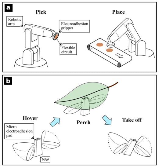
It is highly desirable to equip EA systems with quicker de-adhesion ability, as this could significantly improve the overall throughput of assembly lines where material pick-and-place tasks are involved and produce more efficient and faster locomotion speeds for crawling or climbing robots where EA is employed as their active adhesion and de-adhesion unit. We plan to draw insights from this comprehensive experimental study on speeding up the de-electroadhesion process of an EA gripper, to design future cost effective EA systems that can help speed up the pick-and-place procedure in assembly lines where lightweight and flexible products (e.g., flexible printed circuit boards) are involved and movement efficiency and speed are required. Micro robots, especially micro flapping-wing air vehicles (MFWAV) such as the Harvard RoboBee [
8], have been demonstrated to be candidates for future environmental monitoring, structural health monitoring and security surveillance applications. This work could potentially guide future micro robot designs with integrated EA pads to allow a faster release response.
The rest of this paper is organized as follows: in
Section 2, the EA pad design and its fabrication process are introduced, and the experimental setup is explained; in
Section 3, the experimental results are presented, key findings are discussed, and potential applications that can benefit from this study are listed; and finally, in
Section 4, conclusions are drawn, and future work is discussed.
2. Electroadhesion Pad Release Test
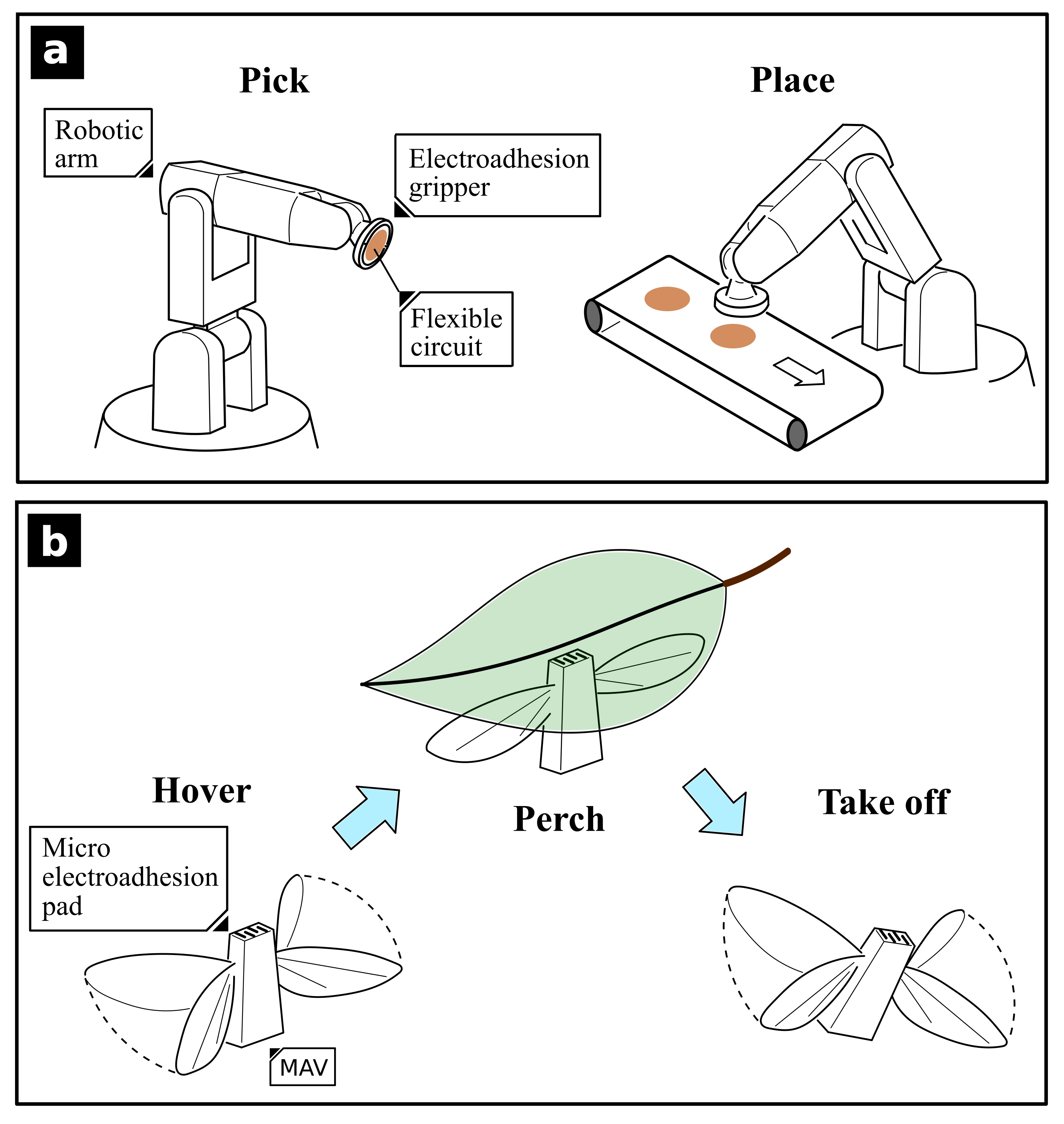
The EA pad design utilized in this work follows a concentric-comb pattern. It has an effective diameter of 56 mm with an electrode width and gap of 4 mm, a schematic diagram of which is shown in
Figure 2a. The electrodes were made of off-the-shelf electrically conductive silicone sheet (0.5 mm thickness, 4.3 Ω·cm volume resistivity, J-Flex, Coalville, UK). The electrode pattern was first designed in computer-aided design software (SOLIDWORKS, Dassault Systemes, Vélizy-Villacoublay, Frence) and was fabricated via a computer-controlled cutter (Provo Craft & Novelty, South Jordan, UT, USA). The electrodes were bonded to the base materials via a thin layer of silicone adhesive (Sil-Poxy, Smooth-On, Macungie, PA, USA). Six different base materials were used: poly (methyl methacrylate) acrylic; medium-density fibreboard (MDF); silicone elastomer (Elastosil, Wacker Chemie AG); polyacrylate elastomer (VHB 4910, 3M); polyethylene terephthalate film (Mylar, Dupont, MI, USA); and polystyrene foam (Styrofoam, Dow Chemical, Michigan, USA), as illustrated in
Figure 2b–g. Eight different object materials were used: balsa wood; polyethylene foam; card board; polyvinyl chloride (PVC) sheet; Mylar; paper tissue; paper sheet; and silicone film. The material properties, dimensions, and mass of both base and object materials can be found in
Supplementary Table S1.
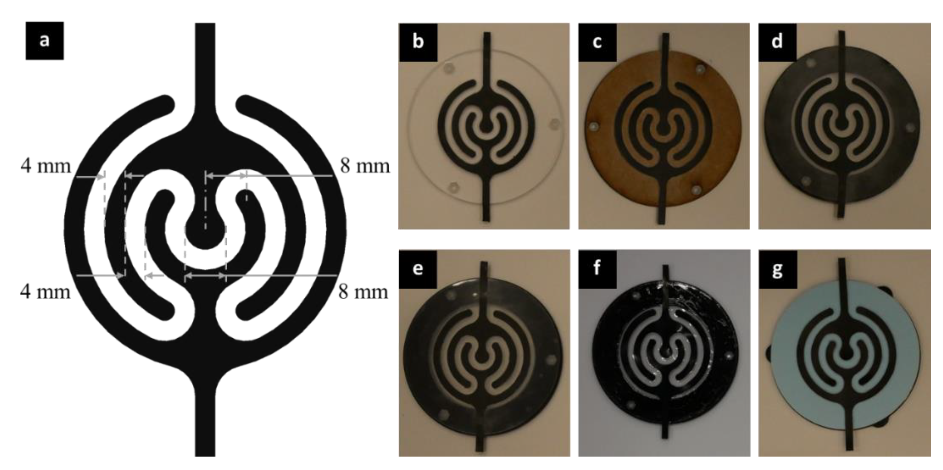
The experimental procedure is summarized as follows, and a schematic diagram of the experimental equipment is shown in
Figure 3. First, the EA pad was moved downward along a linear rail to enable contact with the substrate. A voltage of 3.5 kV was then applied across the electrodes for a total period of 10 s, and after 5 s of actuation, the EA pad, together with the object, was lifted upwards. The EA system was turned off after 10 s charging and the release time measurement began. The release time was defined as the time required to drop off the object from the EA pads after turning off the applied voltage. A high voltage amplifier (HVA) (Advanced Energy Industries, Fort Collins, CO, USA) was used to power the EA pads. A data acquisition device (National Instruments, Texas, USA) was utilized to control the HVA. A linear rail (Zaber Technologies, Vancouver, BC, Canada) was employed to position the EA grippers. The whole process was recorded by a camera at 60 frames-per-second and the release time in each set of experiments was determined from the video. All experiments were conducted in a controlled environment of 23.5 ± 0.5 °C temperature and 45 ± 2% humidity.
3. Results and Discussion
The EA behavior of the insulating material was dependent on its material type and molecular structure. The EA force is a result of polarization
induced by an electric field
[
15]
where
is a constant related to dielectric loss factors,
is time and
is dielectric relaxation time. The polarization describes the separated charges, and the cross product of polarization and applied electric field presents the prehension pressure
[
15],
The dielectric relaxation time is correlated with the molar polarizability,
P, which can be written as [
16]
where
εr is the dielectric constant,
M is the molecular weight of a repeat unit,
ρ is the density. A higher molar polarizability indicates a faster polarizing and depolarizing speed, and hence a reduced dielectric relaxation time.
The polarized charges can be neutralized in the form of a current in an electrically conductive material, since these charges could migrate freely. However, they can barely migrate through insulators and, as a result, cause residual charge. In our experiments, when the electric field was removed, residual charges caused a residual EA force which prevented the object from falling under gravity, demonstrating a slow de-electroadhesion behavior. This is believed to be related to the dielectric relaxation time and the dielectric permittivity of the insulating material [
15].
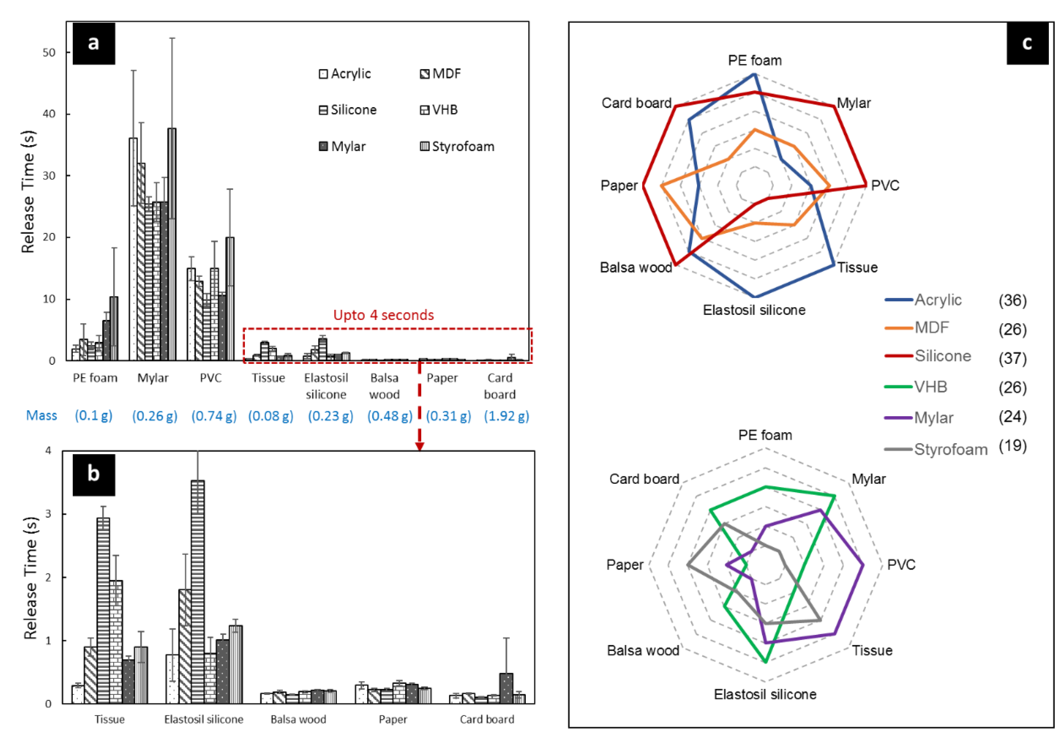
In this work, the de-electroadhesion behavior is characterized by the release time, which is the period between the time when the electric field is removed and the final release. The experimental results are shown in
Figure 4 and detailed comparisons are made in
Figure 5, with raw data available in
Supplementary Table S2 and a video demonstrating the release process available in
Supplementary Video S1. As shown in
Figure 4a,b, the de-electroadhesion behavior was strongly dependent on the material type of the objects. The release time results can be divided into three different time categories: over 10 s (including Mylar and PVC plastic film); between 1 s and 10 s (including Polyethylene (PE) foam and silicone film); and under 1s (including balsa wood, paper sheet and card board). It is clear that plastic-based materials exhibited a longer release period (Mylar shows the worst release behavior) than foam, silicone, and cellulose-based materials, which had the shortest release periods. Note that despite the similar mass, Mylar plastic sheet had an average release period 119 times longer than paper. It is also interesting to note that the lightest object, tissue, needed less than 3 s to release. The key findings are summarized as follows.
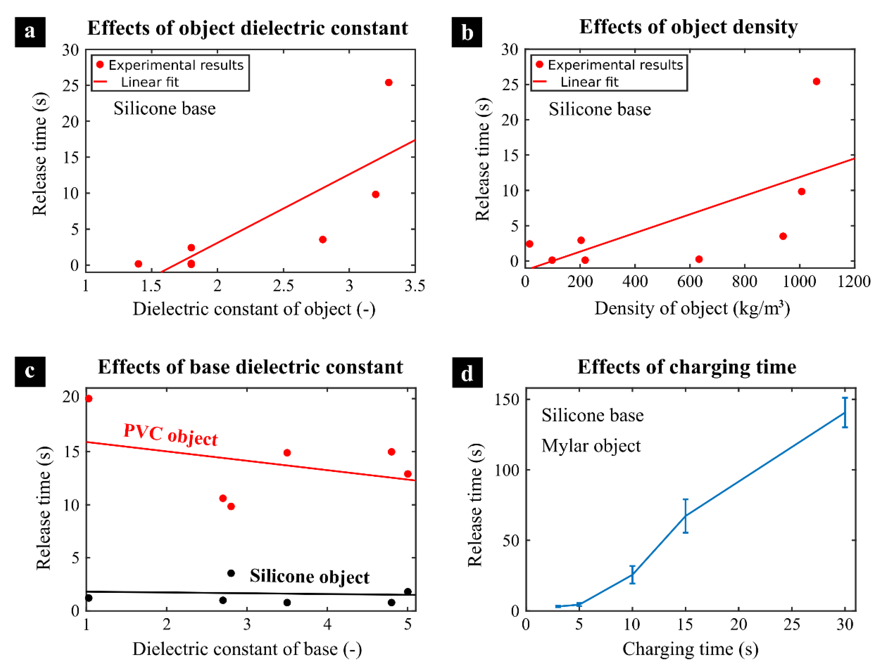
The effect of the dielectric constant of the object. As can be seen in
Figure 5a, as the dielectric constant of the object increased, the release time became longer. Cellulose-based materials had the lowest dielectric constants and the fastest release speed among all objects, while plastic materials had the highest dielectric constants and demonstrated the slowest release behaviors (as listed in
Supplementary Table S1). The strong correlation between the dielectric constant of the object and its release time demonstrated in
Figure 5a can be explained by the increasing electroadhesion force on the object as the dielectric constant increased, which lead to a slower de-adhesion.
The effect of the mass-specific density of the object. The release time and the density of the objects are compared in
Figure 5b. The general trend indicates a longer release time as the mass-specific density of the object increased. This could be explained by the fact that for low density materials such as wood, only the cellulose part was polarized, while the voids in between caused a negligible EA force, which resulted in a reduced total adhesion force compared to denser materials such as PVC. Also note that the molar polarizability was inversely proportional to the mass-specific density (Equation (3)). As the density of the object increased, the molar polarizability,
P, reduced, which lead to a longer dielectric relaxation time and a slower release time.
The effect of the compliance of the object. Although silicone film demonstrated a dielectric constant close to plastics, its release period was significantly shorter than plastics, which might be partially due to its softness. Peeling was observed during the release of silicone object, which indicates that for an extremely compliant material, a peeling effect could also speed up the release period.
The effect of the molecular weight of the object. It can be noted from Equation (3) that the molar polarizability was proportional to the molecular weight, which suggests that the material with a larger molecular weight could have a reduced dielectric relaxation time and a faster release time. This could explain why Mylar had a much worse de-electroadhesion behavior than PVC, despite the close dielectric constant (Mylar molecular weight: 20,326 [
17]; PVC molecular weight: 47,040 [
18]).
The effect of surface roughness of the object. Charge carriers are stored in the object and subsequently transferred to the gripper dielectric after switching off. A smooth surface profile allows better dielectric to dielectric contact, thus the plastics with a smooth surface showed much higher release periods than the others in this study.
During the actuation of an EA pad, polarization not only happens on the object, but also on the base material, causing residual EA force on the base when the electric field is removed. Note that the RC time constant (the product of the resistance and the capacitance) of the EA pad was negligible compared to the residual EA force in this design. The measured RC constant of this EA pad (via a high-precision LCR meter (E4980AL, Keysight)) was in the range of 0.1–1 μs and hence could be safely neglected. The results demonstrate that the de-electroadhesion behaviors of the six EA pads were clearly dependent on the base material. In
Figure 5c, the effects of the dielectric constant of the base material on the release time of PVC and silicone objects are compared. It can be noted that for both PVC and silicone objects (representing slow (10 s) and fast release (0.1–1 s) objects), the release times showed a gradual decrease as the dielectric constant of the base increased. The general negative relationship between the dielectric constant and release time could be explained by the relationship between the molar polarization and dielectric constant in Equation (3). The increasing dielectric constant caused an increase in the molar polarization, and thus a faster release speed. However, it is worth noting that despite this general negative relationship, a global minimum in release time for PVC was found at
εr = 2.8 (silicone base material), which suggests that a more comprehensive comparison between the base materials is needed. To systemically characterize the effects of the base materials, the performance of each EA pad was evaluated based on the release time of the eight objects. For each object, the EA pad’s release time, from the shortest to the longest, was assigned 6 to 1 points according to the ranking, and these points were summed for each EA pad. As shown in
Figure 4c, the EA pad with silicone as the base material had the highest score, while the Styrofoam had the lowest points among all. It can also be noted that despite the highest score, the silicone EA pad had the lowest points (i.e., longest release time) in grasping silicone and tissue substrates. This suggests that for general grasping and release applications, silicone material is arguably the best material for fast de-electroadhesion of EA pads with exposed electrodes, however, for certain objects used in this work, such as the silicone film and paper tissue, acrylic could be a better option for the base material.
Until now, the characterization of de-electroadhesion speed against different material types was based on a fixed charging period of 10 s. Here, the base substrate and object material types were fixed (silicone material for base due to the highest score and Mylar material for the target object) and the charging period was varied from 3 to 30 s.
Figure 5d compares the measured release period of the object as a function of the charging period, and raw data can be found in
Supplementary Material Table S3. It can be noted that as the charging period increased, the release period increased dramatically. For example, the average release period was 3.1 s when the charging period was 3 s, while the release period rose to 140.6 s when the charging period became 30 s, which could be due to a greater amount of charge building in the object and base substrate during the longer charging period. The positive correlation between the charging and release period suggests that a faster de-electroadhesion speed can be achieved by reducing the charging period. However, note that an extremely short charging period could reduce the success rate of lifting up an object. An alternative approach developed by the authors to achieve fast de-electroadhesion is to use a dielectric elastomer actuator (DEA), which is integrated into a flat EA gripper, to generate out-of-plane oscillation and thus force the object to release. For the detailed design of this EA-DEA gripper please refer to [
19].


