1. Introduction
The grounds of construction sites or factories are often muddy or scattered with debris. Under such circumstances, wheeled vehicles used for material handling might be easily blockaded by obstacles or experience skidding on the muddy grounds. Hence, this inspires us to pursue the development of a hexapod robot to replace a wheeled vehicle. However, robots are complex and expensive machines, consisting of many actuators, sensors, transmissions, and hardware. Therefore, a method of developing a hexapod robot to reduce the cost by means of using a minimal number of actuators is proposed. In this article, a hexapod robot was conceived, designed, and built.
In the development of a legged robot, there are two primary concerns, i.e., how to generate a stable gait, so that the robot can walk without tumbling, and how to perpetually generate stable gaits. Regarding the first concern, McGhee and Frank [
1,
2] proposed the COG (center of gravity projection) method in 1968, stating that the legged robot is statically stable if the horizontal projection of its COG lies within the support polygon, which is defined as the convex polygon formed by connecting the footprints. Orin [
3] generalized the COG method in 1976, proposing the COP (center of pressure) method, where a robot is dynamically stable if the projection of the COG, along the direction of the resultant force acting on the COG, lies within the support polygon. In 1969, Vukabratovic and Juricic [
4,
5] further proposed a method in favor of the biped robot called the ZMP (zero moment point) method, where a robot is stable if the moment about the COP, at its supporting foot, is zero. As to the second concern, many rhythmic movements such as locomotion, respiration, swallowing, etc., in animals, have been found to be produced by a CPG (central pattern generator) [
6,
7,
8,
9,
10,
11].
Neuroscientists [
12] have employed a variety of techniques, including anatomical, behavioral, physiological methods, etc., to investigate the specific neural circuits and discover the mapping function in those circuits. One notable study on the locomotion of the salamander [
13] proposed the CPG model based on nonlinear oscillators instead of neural network oscillators, presented numerical as well as mechanical simulations, and successfully constructed a salamander-like robot. Some studies [
14,
15,
16] have addressed to the locomotion of hexapods with CPG and established mathematical models not only including the rhythmic generator, but also the interlimb coordinator, so that the hexapod can adapt to variant terrains by gait transition. Beyond bio-inspiration, a new trend of research that is noteworthy is the merging of natural and artificial components, which is defined as bio-hybrid organisms [
17,
18], also called bio-robots, in which an artificial component or a biological organ is incorporated into an animal or robot, respectively. These studies even investigate how the artificial agent interacts with an animal individual or a population. So far, all studies have relied on electronic circuits or processors to implement the locomotion of legged robots.
Computers have always been thought of as nothing more than electronic devices, which is not necessarily the case. Recalling the evolution of computer science, the earlier computing devices, called calculators, invented by Blaise Pascal of France (1642) and G.W. Leibniz of Germany (1671), were built with the technology of gears. In fact, they were mechanical calculators, where data was represented through gear positioning and entered mechanically, by adjusting the initial gear positions. The output of the calculators was achieved by observing the final gear positions. Therefore, mechanical devices can be regarded as computational processors, as long as they execute certain mathematical operations. This was the inspiration to create a mechanism, or mechanical computational processor, to complement the electronic processors.
Moreover, neuroscience discovered that the CPG, located in the spinal cord, is an autonomous device, almost requiring neither the peripheral sensor feedback, nor the regulation command from the brain-stem. Therefore, a hexapod robot with biomimetic legs was built, to implement such a distributed control system, where a mechanism is proposed to serve as the CPG and a computer acts as the brain-stem, to command the autonomous device through wireless communication. In a sense, we are trying to implement the locomotion of a robot by means of a hybrid computational system, including a mechanism and electronic computers. The proposed mechanism comprises two modules, i.e., the tripod gait generator and the Theo Jansen Linkage. The tripod gait generator is a device that uses a single motor to generate a tripod gait that couples the middle leg on one side with the front and rear leg on the other side, while the TJL (Theo Jansen Linkage) rhythmically executes the legged motion.
The TJL was first introduced by Theo Jansen in 1990, where he presented a strandbeest [
19], elegantly achieving a bio-inspired locomotion. This soon drew the attention of robotics researchers [
20,
21,
22,
23,
24,
25]. The TJL adopted in this paper is an eight-bar linkage. The interesting point is that the foot movement is a complex mathematical function, from a crank to a rocker. Nonetheless, it can be simply realized by the combination of these eight links. Consider that, if the same function is processed by an electronic device, it will consume a great amount of computational time and memory resources. Therefore, our proposed mechanism can alleviate the computational burden. Moreover, most hexapods are designed with collocated actuators, i.e., each joint is mounted with an actuator, so the number of actuators is usually high, reaching even 18, in number. Using a high number of actuators leads to many adverse effects, including increased challenge for the algorithms to control legged motions, degradation of the loading capacity, and increase of the construction cost. Hence, the present proposed design is based on non-collocated actuators, so as to minimize the number of actuators while reducing the building cost of the robot.
2. Mechanical Structure
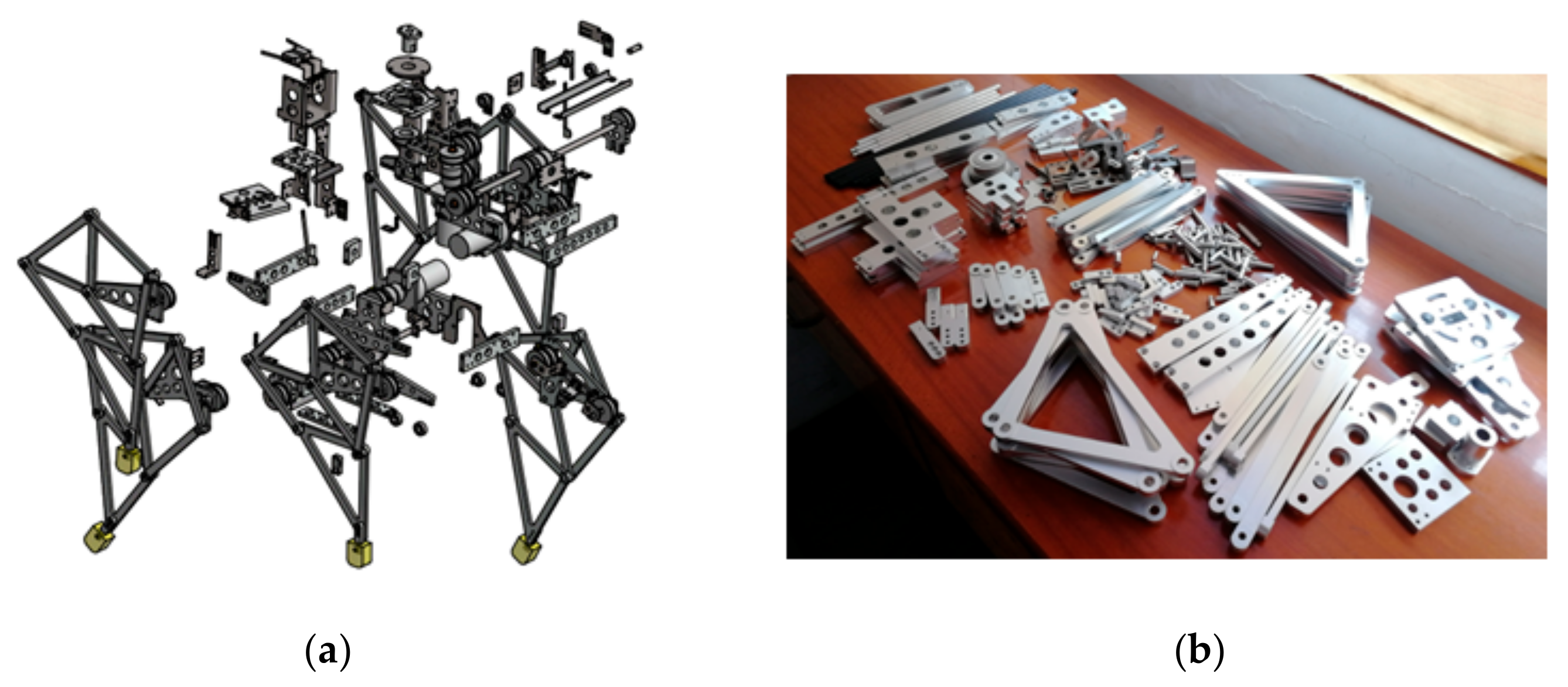
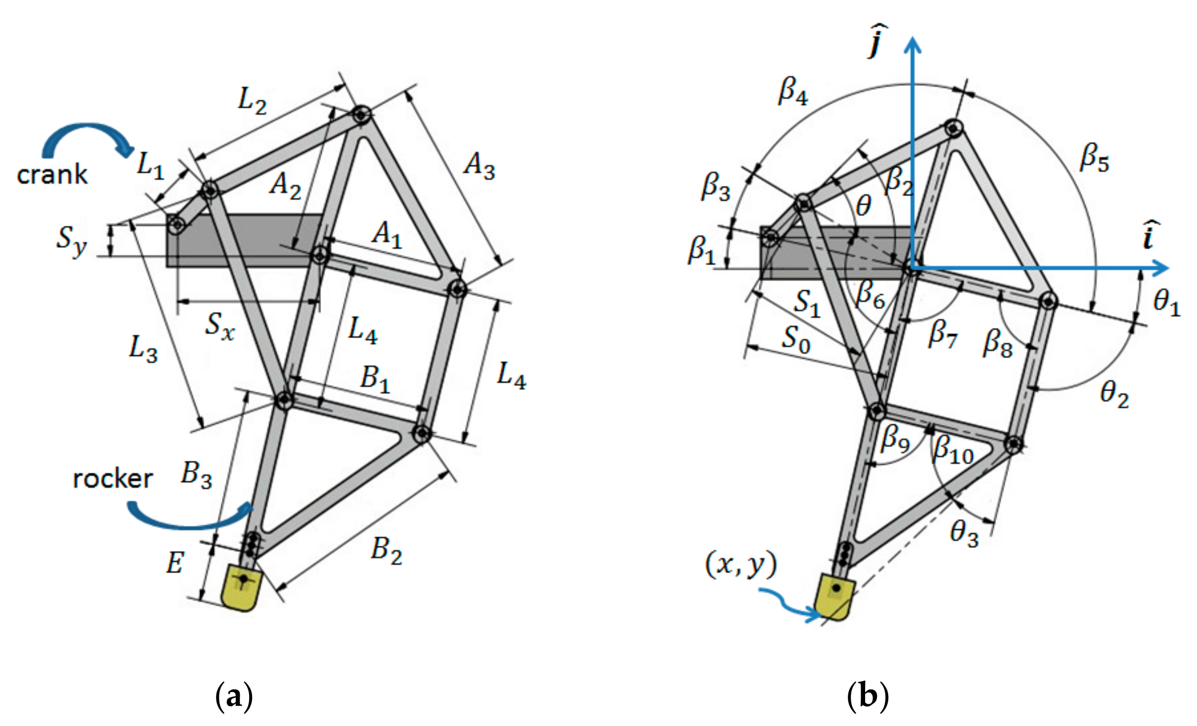
The TJL can be built using either 8 or 12 links, depending on the fabrication method of two triangular links of the TJL. If each triangular link is machined into a whole piece, the TLJ is an 8-bar linkage, whereas if each of them is assembled by three straight bars, the TLJ is a 12-bar linkage. The TJL, as adopted in this paper, is the eight-bar linkage option. It can be considered as a device to implement the mathematical function for the legged motion, as will be presented in the Kinematics section. As illustrated in
Figure 1, the complexity of the foot movement implementation is not in any way reduced, but rather a passing from the computer to the mechanism occurs, i.e., coding is replaced by component designing. Once the ensemble of links is determined, it can generate a deterministic orbit.
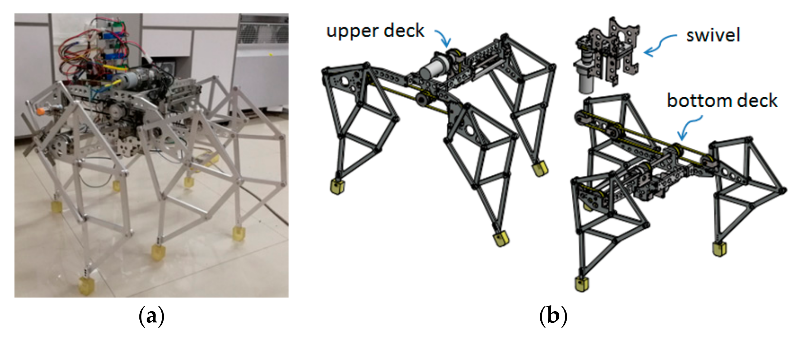
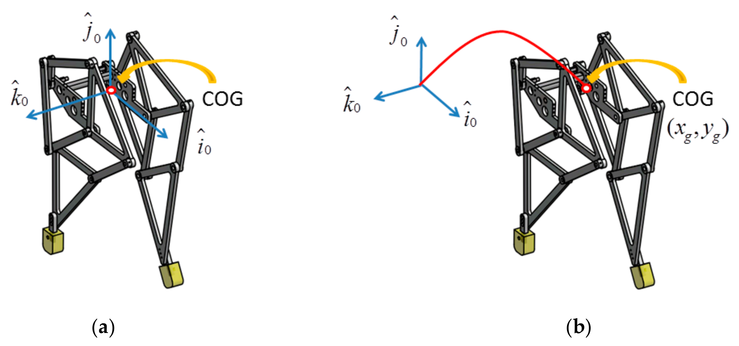
The hexapod robot (
Figure 2a) is divided into three modules, i.e., an upper deck, a bottom deck, and a swivel connecting the both of them (
Figure 2b). In regard to manufacturing or maintenance, we should avoid diversifying the components design-wise. Instead, it is more practical to design the components shared by different modules. Hence, both decks are designed according to the same structure except their legs, which are mounted with opposing orientation. Therefore, it is adequate to study just one of them, while the bottom deck will be used for illustration purposes.
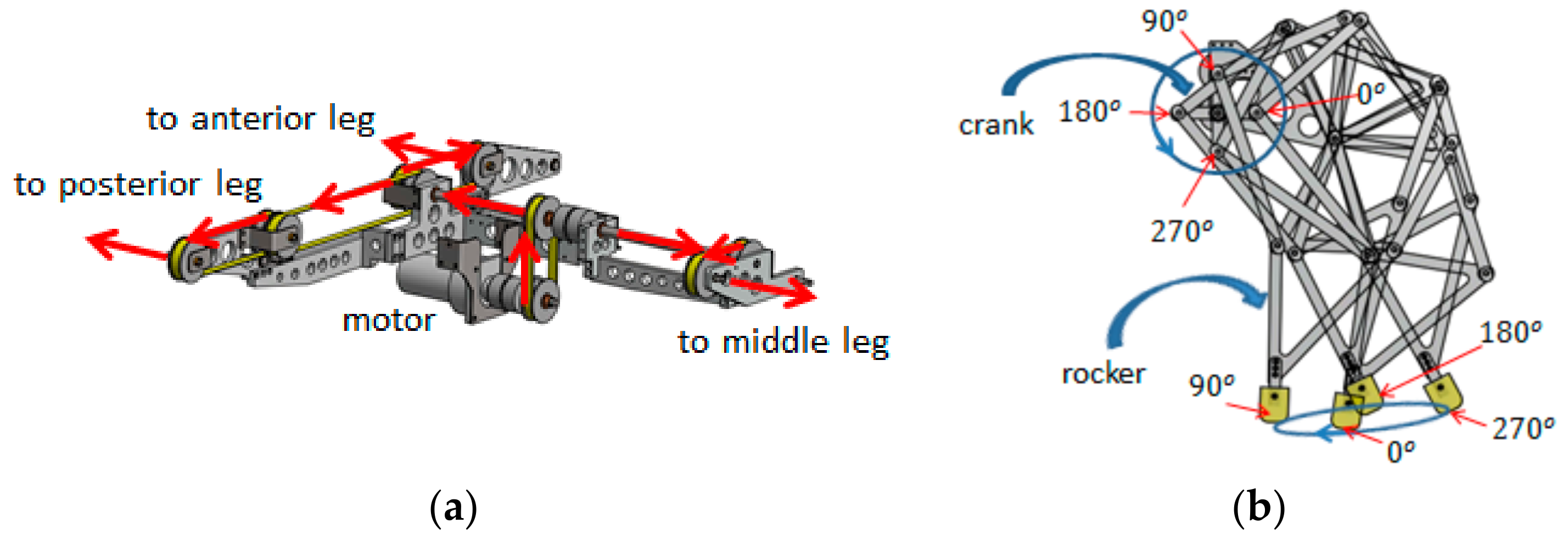
The bottom deck consists of one tripod gait generator and three TJLs. The tripod gait generator is a module dispatching power from a motor to three legs (
Figure 3a), each of which is a TJL.
Let the crank of a TJL pose at four different angles, i.e. 0°, 90°, 180° and 270°. Consequently, these four postures of the TJL are superimposed, showing the motion of the rocker in relation to the crank. In
Figure 3b, the tip of the rocker draws an orbit, in a sense opposite to the rotation of the crank, as the four phase angles of the crank, labeled at the foot trajectory, help acknowledge how the rocker is related to the crank during motion.
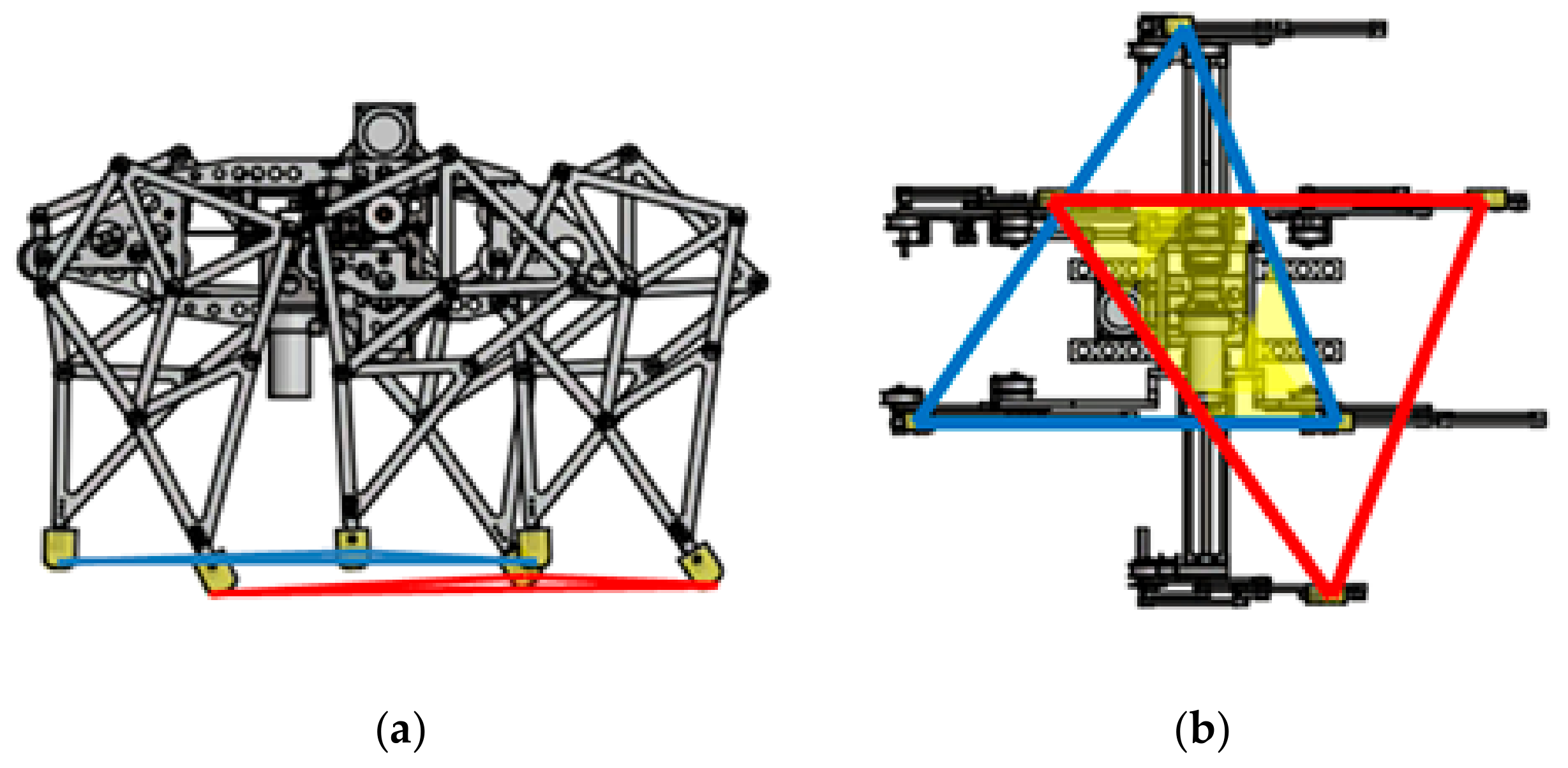
The tripod gait module is also a device which couples the middle leg on one side with the front and rear on the other side, to rhythmically generate tripod gaits. The locomotion of the hexapod is achieved by alternating two support polygons, each being the triangle connecting the tips of the rockers (
Figure 4).
3. Kinematics
The kinematics of the TJL (
Figure 5) can be derived according to the Denavit–Hartenberg [
26] convention, along with certain trigonometric constraints. Hence, the orbit of the foot tip is a function of the input variable
θ, also referred to as the crank angle, and defined as follows:
where
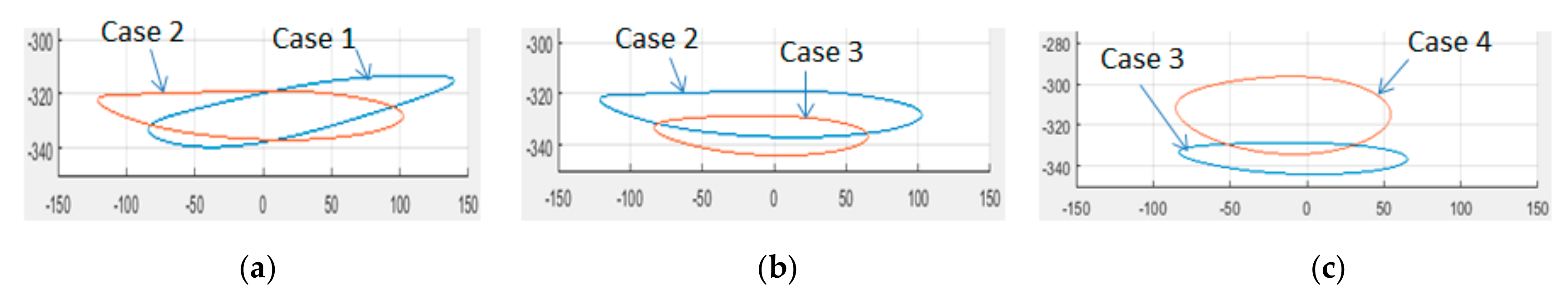
The orbits patterns produced by TJLs might end up as bell curves, ovals, sharp-pointed ovals, or lemniscates, depending on the assembly of their variant sizes. Not all generated orbits are suitable to serve as foot trajectories for the legged robots. Hence, dimensioning the TJL appropriately is nontrivial, since the orbits patterns generated by a TJL may vary according to its assembled dimensions, and can be cast into four groups, including bell curves, ovals, sharp-pointed ovals, and lemniscates. In general, the ovals or bell orbits are legitimate, while the sharp-pointed ovals are partly legitimate, and the lemniscates are illegitimate. After analyzing and balancing requirements, the design data of L4, A1, A2, A3, B1, B2, B3, E, Sx, and Sy were set to be 140, 135, 140, 190, 135, 200, 150, 55, 135, and 30, respectively.
In
Table 1, four cases of links with different lengths:
L1,
L2, and
L3, are illustrated along with the respective data of foot trajectories, demonstrating how they are influenced by the variant links. Although all four cases include legitimate orbits, there are some other concerns to be taken into account in order to achieve a satisfactory design. The maximum step size is defined as the distance between the leftmost point and the rightmost point. Similarly, the maximum step height is defined as the distance between the topmost point and the bottommost point. Although both of these are different from the actual step size and height, they are able to show the effectiveness of the following actions. Regarding the actual step size and height, a slightly more complicated calculation is required, which will be presented in the next section.
Indicatively, in the trajectory of Case 1 (
Figure 6a), where the inclination is too deep, the corrective measure, taken by Case 2, is to reduce the lengths of
L2 and
L3. Nonetheless, as mentioned earlier, the stability of the hexapod is ensured by the intersection of two support polygons. Given the fact that, the larger the stride, the smaller the intersected polygon will be, the hexapod will eventually be destabilized if the stride is too large. In order to ensure stability, the action taken by Case 3 is to shorten the step size, by reducing the length of
L1 (
Figure 6b). After these efforts, the hexapod is ready to walk. However, its step height is relatively small, so the further action, taken by Case 4, is to increase the step height (
Figure 6c), by the fourth set of data in
Table 1.
4. Locomotion
The locomotion of this hexapod can be analyzed in terms a simplified model (
Figure 7), a biped robot with absolute stability, by regarding the left and right legs of the biped version as the legs of the upper and lower deck of the hexapod, respectively. Following this, the locomotion of the robot can be characterized by the motion of its COG (Center of Gravity).
The cranks of the left and right legs will keep apart by 180° during rotation, and
Figure 8 illustrates how the motion of the COG relates to the foot trajectory where (x,y), (x
g,
yg),
Ls,
Hs, and
Mg stand for the foot trajectory, the motion of the COG, the step size, the step height, and the fluctuated amplitude, respectively.
The robot is initially at rest with one foot standing at point A, while another foot stands at point B. The coordinates of point A are denoted as (
xs,
ys), which is associated with the crank angle
, while the crank angle of point B is 180° apart from
, i.e.,
. Hence, point A can be obtained by determining the crank angle
, where the height of point A is equal to the height of point B, using Equations (1)–(16). Following, the step size
Ls, step height
Hs, and fluctuated amplitude
Mg, are calculated and listed in
Table 2.
As the foot engages on point A, it pushes the robot forward, as well as upward. Hence, by mirroring the part of foot trajectory ABC, with respect to the horizontal and vertical axes, the locus of the COG is derived, yielding the following equations:
where, the bracket
yields the maximum integer, no greater than the value it contains.
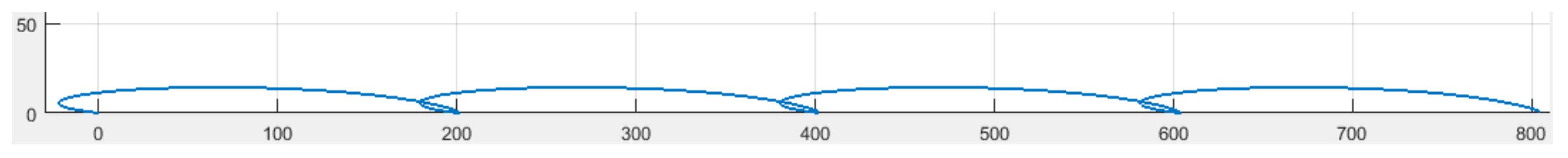
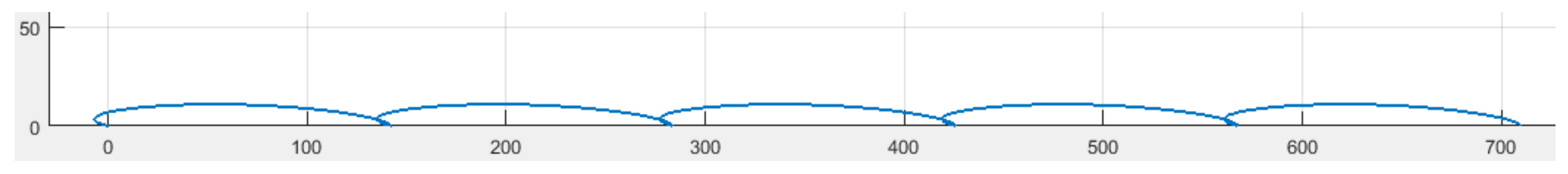
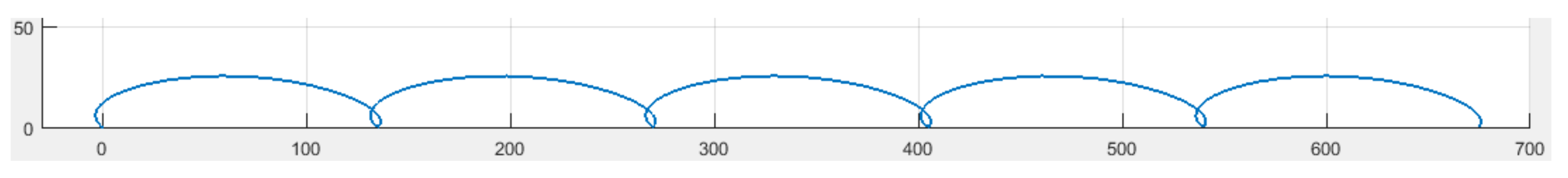
The locomotion of the robot, i.e., rhythmically alternating one foot with another, can be well characterized by the locus of its COG, using Equations (17)–(19). The loci of the COG pertaining to four different cases are as shown in
Figure 9,
Figure 10,
Figure 11 and
Figure 12.
In
Figure 9, the locus manifests that the robot will wobble significantly, while moving. This adverse effect arises from the fact that the foot trajectory, generated by the TJL in Case 1, exhibits large obliqueness. In an effort to improve this situation, the inclination of the orbit was reduced, causing a side effect on the actual step size, i.e., an increase by 1.5 times (
Figure 9 and
Figure 10). The maximum step sizes in Cases 1 and 2 (
Table 1) are almost the same and the respective orbits (
Figure 6a) are similar. Evidently, the actual step size is not only determined by the orbit itself, but also by the points where the feet meet the ground, i.e., point A and point B (
Figure 8).
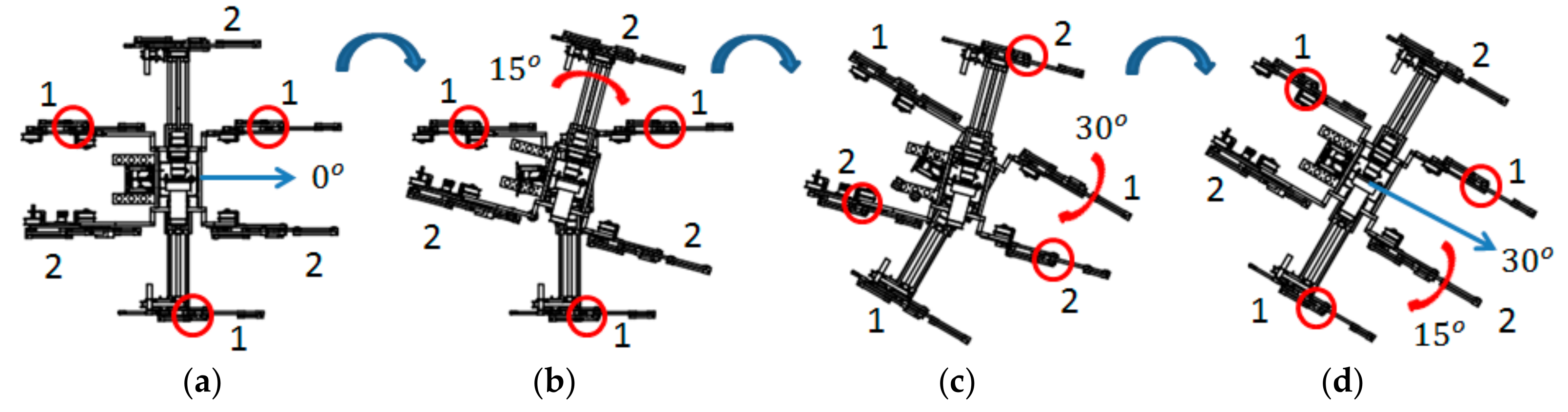
Moreover, the robot can change its azimuth by a swivel mechanism, located between the upper and bottom deck. In order to avoid mechanical collision, the swivel motor is limited to rotate within ±15°. However, the robot is still able to manage turns greater than ±15° through a sequence of detailed maneuvers of its swivel and legs. An example is illustrated in
Figure 13. Considering that the body and output shaft of the swivel motor are connected to the bottom and upper deck, respectively, the swivel motor has to reverse its output shaft, depending on which set of legs is standing on the ground, as the robot changes its azimuth. In
Figure 13b, the swivel motor turns clockwise, to swing the upper deck in the same direction, while the legs of the bottom deck stand statically on the ground. In
Figure 13c, the swivel motor turns counterclockwise to swing the bottom deck in the opposite direction, i.e., clockwise, when the legs of the upper deck stand statically on the ground.
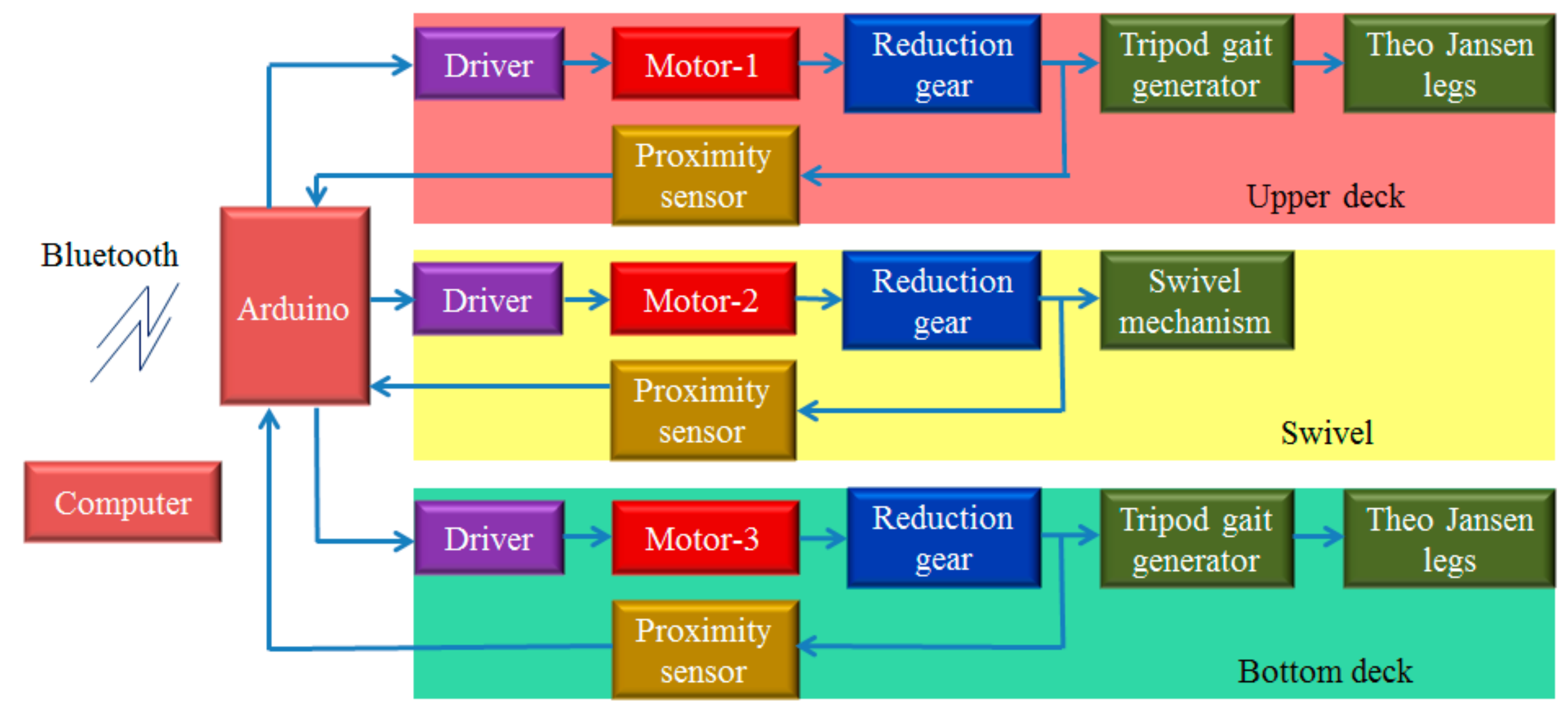
5. Mechatronics of the Control System
Following the analysis and construction of the mechanism, the mechatronics of the control system (
Figure 14), consisting of a microcontroller, drivers, sensors, and motors with gear trains, was built.
This part mainly controls the orientation of the swivel and the motions of the TJLs, with a phase of
between the two sets of cranks. The Arduino was chosen as the microcontroller for this project. Since the first Arduino [
27] was introduced in 2005, it has become one of the most popular microcontrollers used by engineers and even large corporations. The appealing features of Arduino are mostly its openness and ease-of-use. It is worth mentioning that the programming of an embedded system is done according to cross-development principles, so that the code can run on a target boar, different from the one where the code was built. The Arduino provides an integrated development environment (IDE) for users to edit, debug, and compile their application programs on a personal computer and then upload them to the Arduino board for execution.
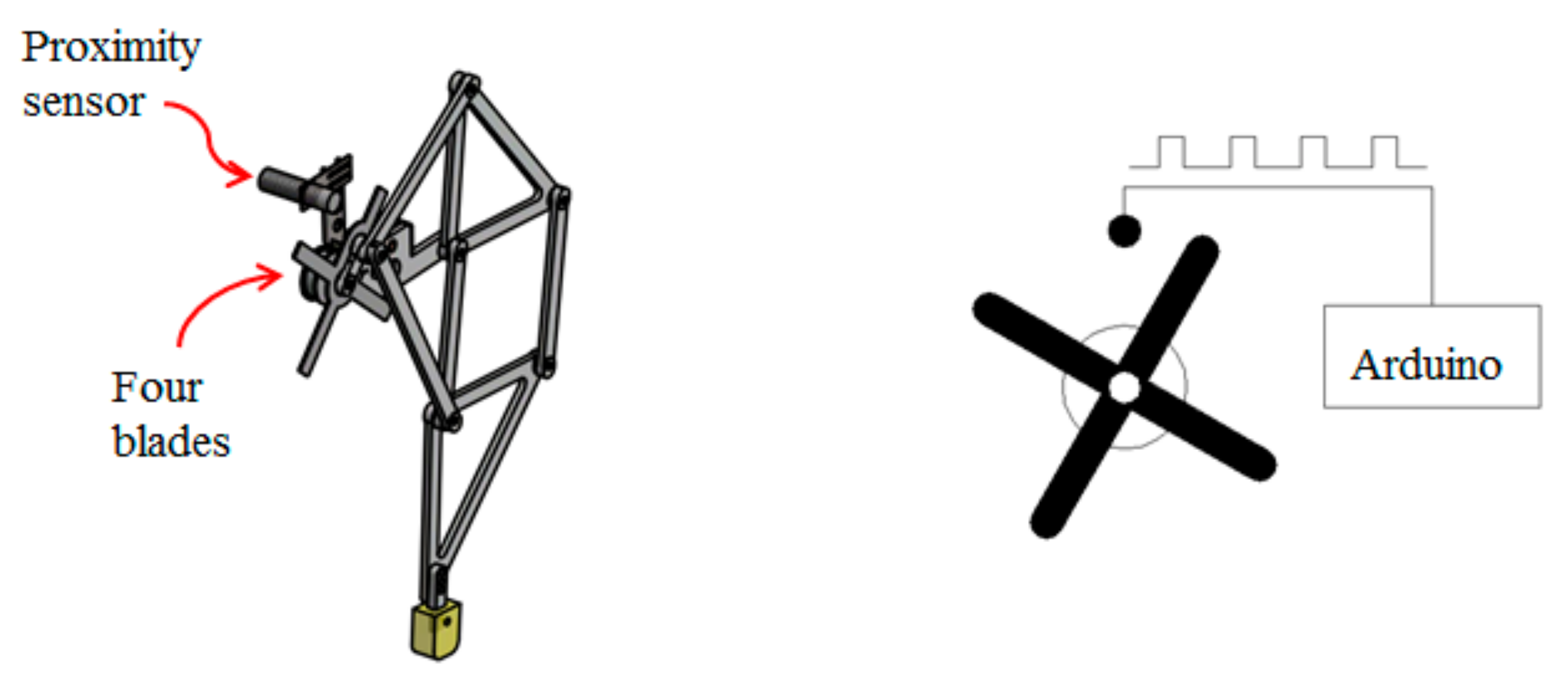
In
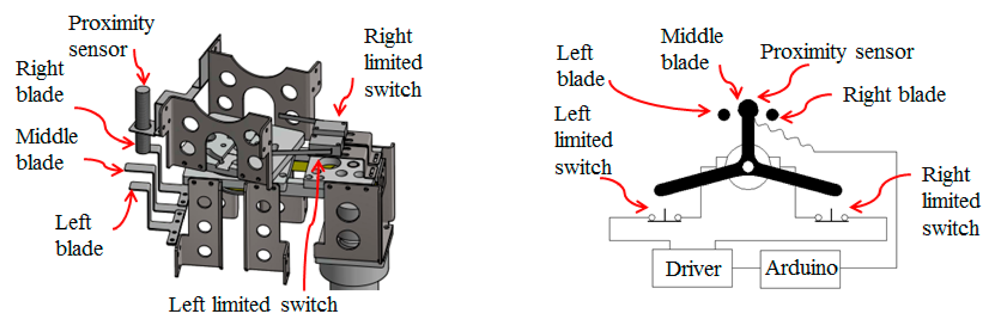
Figure 15, the crank of the TJL is attached through four metal blades, evenly partitioning the circumference into four quarters. The proximity sensor, CHIIB LJ18A3-10-Z/BY, is used to detect four phases of the crank, based on which the Arduino is able to keep the two sets of cranks apart, at 180°, during operation. Regarding the control of the swivel (
Figure 16), specific care needs to be taken to avoid mechanical collision. First, one system, consisting of a proximity sensor, CHIIB LJ12A3-4-Z/BY, and three metal blades, is installed to receive feedback on the azimuth of the swivel. Second, another system, using two limited switches as a safety guard to assure that the range of operation is maintained, is installed. When the swivel reaches its maximum range, it will push the leverage of the limited switch, so as to cut off the power of the swivel motor immediately. Without the safety guard system, the catastrophe of a mechanical collision is inevitable in developing the application programs. Regarding the DC motors, there are two motors with specifications of 12 V, 2 A, 35 W, 30 rpm, and 25.47 kg-cm, used for the TJLs and one motor with specifications of 12 V, 2 A, 35 W, 10 rpm, and 76.4 kg-cm, used for the swivel. The drivers are all in typical H-bridge with specifications of 12–36 V, 10 A, and 120 W.
In this project, Bluetooth (BT) was used to establish wireless communication between the computer and the Arduino. Bluetooth is a wireless technology standard, IEEE 802.15.1, for exchanging data between fixed and mobile devices over short distances, most often within 10 m, using short-wavelength UHF (Ultra High Frequency) radio waves, in the industrial, scientific and medical radio bands, from 2.400 to 2.485 GHz, and in personal networks.
AT (Attention), commands are instructions used to control a modem. Every command line starts with “AT” or “at,” which is why modem commands are called AT commands. Some AT commands used to configure the BTs and a portion of Arduino program, related to the wireless communication, are provided in
Table 3. The BTs need to be set up before communication. First, the KEY-pin is set to high, before powering up the BT. As the power is turned on, the BT enters a setting mode, where its LED blinks with a period of four seconds, i.e., light on for two seconds and light off for two seconds. Then, AT commands are used to configure the baud rate, parity, stop bit, password, master/slave, binding address, etc. Following this, the power is turned off and the KEY-pin is set to low. As the power is turned on again, the BTs enter a standby mode, where they blink every second, in an attempt to pair up. At successful pairing up, both BTs get into the communication mode, where they blink twice for two seconds and light off for two seconds. Upon completion of the mechatronic control system, programs were developed, where the Arduino side mainly awaits the commands from the computer and keeps two sets of cranks apart at 180° during operation, while the computer side sends wireless commands to the Arduino. Since the legged motion has been realized by the mechanism, there is no need to develop a sophisticated algorithm in Arduino.
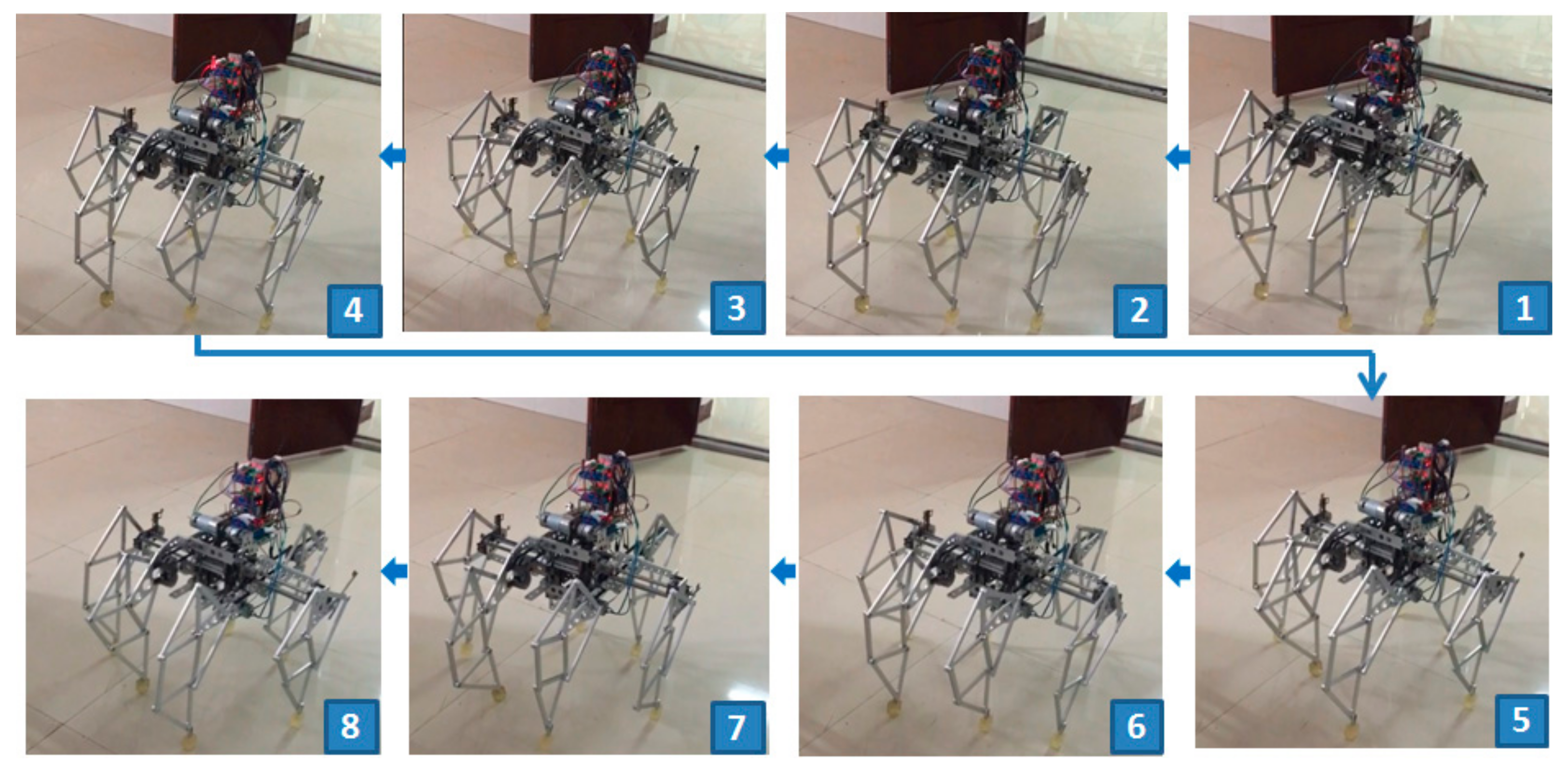
In
Figure 17, a sequence of snapshots of the hexapod robot, as tested on site, is illustrated. The appealing feature of this robot is that it is reliable and robust. Even if it runs out of battery or an electronics failure occurs, it can still stand because the tripod gaits are generated by the mechanism, instead of the computer.
6. Comparison to Existing Hexapods
For the sake of comparison, an overview of existing hexapod robots is conducted in this section. Since the first hexapod robot with electric drivers and a computer-controller [
28] was built in 1972, a variety of hexapod robots have been constructed according to varying technologies and design principles. Several hexapod robots limited to 14 kg at maximum are listed in
Table 4.
Biobot [
29], inspired to the cockroach, was a hexapod with a great speed and agility. Hamlet [
30] was built to study force and position control on uneven terrain. RHex [
31], designed in mechanical simplicity and having only six actuators, can achieve fast and robust forward locomotion. Sprawlita [
32] was based on functional principles derived from biomechanical studies of the cockroach to achieve a fast run. Genghis [
33] presented an incremental method for building robot control systems analogous to evolution of the organism, i.e., each one being a strict augmentation of the previous one, which control a six legged walking machine. Bill-Ant-p [
34], based on ants’ behavior, was developed and consisted of 18 degrees of freedom for locomotion, i.e., each leg with three actuators and one force-sensing foot. Gregor I [
35] is also a bio-inspired hexapod where the locomotion control is based on the CPG and the core of its control architecture is the Cellular-Nonlinear-Network CPG chip. RiSE [
36] is a hexapod robot which is able to climb on a variety of vertical surfaces. It employs arrays of miniature spines to catch on surface asperities.
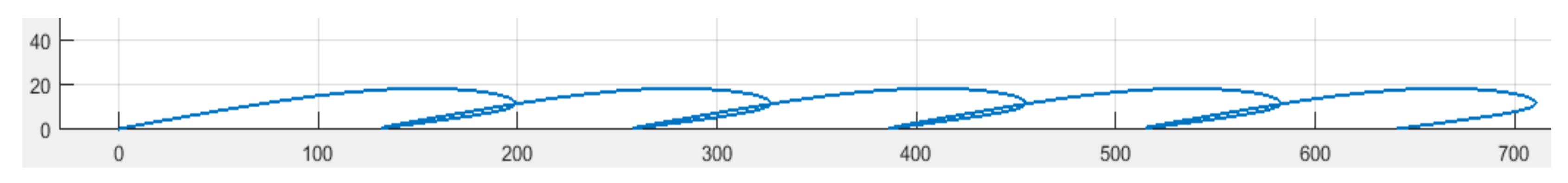
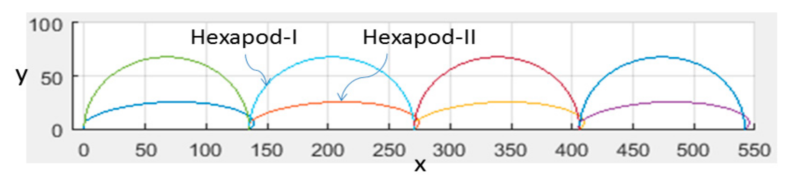
The hexapod robot of this article, named Hexapod-II, is an improved version of the Hexapod-I [
37]. The difference between Hexapod-I and Hexapod-II lies in their biomimetic legs. The former uses four-bar linkages, while the latter uses the TJLs. The four-bar linkage can only generate a circular orbit, which leads the hexapod robot to move in a way with a larger fluctuation (
Figure 18) because its step height is always one half of its step size, as two tripod gaits are alternated with a phase lag of 180°. In contrast, the TJL generates an ellipse-like trajectory which possesses a transversal axis longer than the lateral axis, so that it can achieve energy efficient walking, as compared to the circular orbit generated by the four-bar linkage.
Note that the cost of a robot is generally proportional to the number of actuators. Therefore, the cost can be roughly estimated by counting the number of actuators. Taking a glimpse at
Table 4, the numbers of actuators used by other hexapods are all much higher than the number of actuators used by our robots, i.e., Hexapod-I and Hexapod-II. This is due to the novelty of our approach, which uses the mechanical mechanism rather than electronic circuits or computers to act as the CPG in achieving the locomotion.
7. Conclusions
According to neuroscience, a distributed control system is proposed for the locomotion of a legged robot, since the CPG, located in the spinal cord and in charge of the rhythmic motion, is an autonomous device, almost requiring neither the peripheral sensor feedback nor the regulation command from the brain-stem. A hexapod robot with biomimetic legs was built to realize such a distributed control system, where a mechanism is proposed to serve as the CPG and a computer to act as the brain-stem, wirelessly sending commands to the autonomous device. The proposed mechanism consists of two modules, i.e., the tripod gait generator and the Theo Jansen Linkage. The tripod gait generator is a device that uses a single motor to generate a tripod gait, while the TJL rhythmically executes the legged motion. The interesting point is that the complex mathematical function of the foot motion can be realized by the ensemble of links of the TJL. If the same function is executed by an electronic computer, it will require a great amount of the computational time and memory resources. Nevertheless, dimensioning the TJL appropriately is nontrivial, since the patterns of orbits generated by a TJL may vary according to its overall dimensions and can be cast into four groups: bell curves, ovals, sharp-pointed ovals, and lemniscates. In general, the ovals or bell orbits are legitimate, the sharp-pointed ovals are partly legitimate, while the lemniscates are illegitimate. Once the dimension of a TJL has been determined, it can generate an ellipse-like orbit with a transversal axis longer than the lateral axis, so as to achieve energy efficient walking.
Admittedly, the mechanical computer is inferior to the electronic computer in regards to flexibility. Therefore, in the future, efforts should be taken introduce the adjustable mechanical structure to increase the adaptability of this line of approach. Although the proposed method is not suitable for the case of a legged robot, adapted to diversified terrain, it suits the case of a legged robot operating in a specific environment with relative unevenness, such as construction sites, where the grounds are somewhat muddy and rugged, or factories, where the floors are scattered with debris. Our aim is to build a hexapod robot for material handling, since using a legged robot as a mobile platform is still more effective than using a wheeled robot with regards to crossing obstacles and avoiding skidding.
Robots are, in fact, complex and expensive machines, consisting of many actuators, sensors, transmissions, and hardware. Designing a robot capable of especially excessive function can further increase its cost. The cost of building a robot is generally proportional to the number of actuators it uses. For instance, most hexapod robots, designed with collocated actuators, require 18 servos. Based on the design of non-collocated actuators, the proposed hexapod robot uses merely three motors. The value of this approach lies on the fact that it gives a way of building a hexapod robot with much low cost. The significance of this research is in employing a mechanical mechanism, rather than electronic circuits or computers, to act as the CPG in achieving locomotion.


