Abstract
In order to realize automatic steering controls of rice transplanters in paddy fields, an automatic steering control algorithm is essential. In this study, combining the fuzzy control with the proportional-integral-derivative (PID) control and the kinematics model, a compound fuzzy PID controller was proposed to adjust the real time data of the PID parameters for the automatic steering control. The Kubota SPU-68C rice transplanter was then modified with the new controller. Next, an automatic steering control experimental with the modified transplanter was carried out under two conditions of linear tracking and headland turning in verifying the automatic steering effect of the transplanter in different steering angle situations. The results showed that the deviation with the new controller and the modified transplanter was acceptable, with maximum deviation in linear tracking of 7.5 cm, the maximum headland turning a deviation of 11.5 cm, and the average a deviation of less than 5 cm. In conclusion, within the allowable deviation range of the field operation of the rice transplanter, the proposed algorithm successfully realized automatic steering controls of the transplanter under different steering angles.
1. Introduction
With the development of computers, automatic control, intelligent agricultural equipment technologies, and automatic navigation technology has received increased attention in the field of intelligent agricultural machinery [1,2]. The automatic steering control system in navigation is a key step in providing support for subsequent navigation control [3,4]. Many different control methods have been developed for the automatic control system, including the pure pursuit model [5,6,7,8], the proportional-integral-derivative (PID) control [9,10], the fuzzy control [11,12,13], and the neural network [14,15,16,17]. Among these, the pure pursuit model is the most commonly used approach for the automatic control. The main aim of the pure pursuit model was to establish a dynamic model which considers the steering angle as the control variable [18,19]. When accurate mathematical models are not available, another option is to design a controller based on the PID control, the fuzzy control, and the neural network to realize automatic steering controls for agricultural machines.
In order to improve the automatic operation level and realize automatic steering controls for rice transplanters, much research has been done. Nagasaka et al. [20] developed an automatic steering method for a rice transplanter, which includes path tracking and steering with a fixed front wheel angle. This method occupies small headland space; however, it needs to be reversed when headland turning. However, the steering control was complicated and the work efficiency was low. To simplify the steering control structure, a new ground steering control algorithm, based on the Kubota SPU-60 rice transplanter, was proposed [21]. This algorithm applies a two-wheeler model to dynamically plan a steering path and adjust the reverse stance, which is without position feedback and reverse steering; however, the steering control accuracy is not high. In 2011, Xu [22] designed a fuzzy controller and established an automatic steering control method based on the fuzzy control to improve steering control accuracy. The fuzzy controller takes the rotation angle deviation and deviation change rate as inputs and the motor frequency as the output. This method can meet the needs of the agricultural machinery operation, but the stepper motor will drift, which will affect the control precision. To solve this problem, a PD (proportional-derivative) controller was introduced to build an automatic steering control method [23], in which P and D parameters are adjusted online, according to the traveling speed of the agricultural machine, and the desired steering angle of the steering wheel is the output of the controller. It has good control performance, high stability, and fast response speed, though the parameter acquisition is more difficult.
However, it is difficult to establish an accurate mathematical model and acquire parameters for the mentioned controllers above, due to the nonlinear and time-varying characteristics of the steering system of rice transplanters and the complex operating environment. The PID controller has the advantages of a simple principle, a convenient operation, strong adaptability, and high robustness, and its control quality is insensitive to changes in the controlled object. With these characteristics, the PID controller is very suitable for agricultural machine operating in a complex environment. The fuzzy controller does not need to establish an accurate mathematical model, making control mechanisms and strategies easy to accept and understand, and has high robustness and self-adjustability [24,25]. Therefore, an automatic steering control algorithm was presented by taking full advantage of the fuzzy control and the PID control. Firstly, the kinematics analysis of the transplanter was carried out, combining with the fuzzy control, the PID control and the kinematics model, a compound fuzzy PID controller was designed, with the appropriate PID control parameters able to be selected in real time. Then, the steering actuators of the experimental platform were modified, and the simulations and field experiments were carried out in verifying the feasibility of the compound fuzzy PID control system. The simulations and field experimental results show that the compound fuzzy PID controller has good automatic steering tracking performance and control effect, which satisfies the field performance requirements of the transplanter.
2. Materials and Methods
2.1. Automatic Steering Experimental Platform
The Kubota SPU-68C rice transplanter was chosen as a research object in this study. The modular design was used to modify the experimental platform without changing the original structure of the transplanter steering system. The modified experimental platform is shown in Figure 1, which includes a rice transplanter body, a Beidou high-precision differential positioning system, and an automatic steering system.
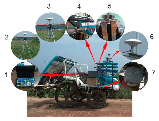
Figure 1.
Automatic steering control experimental platform. (1) Navigation controller; (2) reference station; (3) base station antenna; (4) automatic steering system; (5) steering servo motor; (6) antenna of the movable station; (7) steering angle sensor of the front wheel.
The Beidou high-precision differential positioning system consists of a base station and a mobile station. The base station includes one receiver, one measurement antenna, and one radio communication module. The mobile station contains one receiver, two measurement antennas, and one radio communication module. The base station provides a reference coordinate signal to the mobile station through the radio communication module. The navigation controller was composed of a host computer PC (personal computer) and a lower computer STM32 (Stmicroelectronics 32-bit series) single chip development board. The compound fuzzy PID automatic steering algorithm was stored in the host computer, and the lower computer was connected with the automatic steering system and a wheel angle measuring sensor. The navigation controller makes processing decisions according to the position and angle information outputted by the Beidou positioning system and the front wheel angle sensor. The compound fuzzy PID controller sent a control signal to the automatic steering system in realizing the automatic steering of the rice transplanter. The automatic steering system was a modified automatic steering actuator, as shown in Figure 2. The servo motor and the gear pair are mounted on the modified automatic steering actuator on the rice transplanter to drive the original steering wheel shaft. The perform structure can realize the coexistence of a manual and automatic operation and has the characteristics of a compact structure, high transmission efficiency, low installation cost, and fast response speed. The main parameters of the navigation hardware for the experimental platform are shown in Table 1.
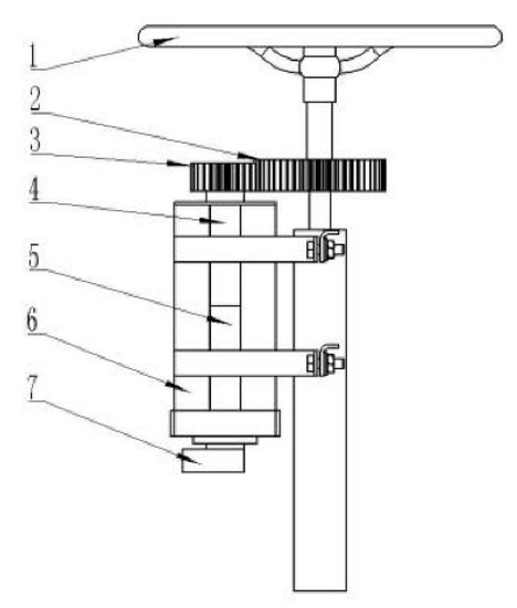
Figure 2.
Actuator of the automatic steering system. (1) Steering wheel of the transplanter; (2) steering axle gear; (3) output axle gear; (4) reducer; (5) servo motor; (6) motor bracket; (7) absolute encoder.

Table 1.
Parameters of the navigation hardware for the experimental platform.
2.2. Analysis of Kinematics of Rice Transplanter
The working environment of the agricultural machine is complex and varied, especially the operation environment of the rice transplanter in the paddy field. To simplify the kinematics model of the vehicle, the transplanter wheel was regarded as a rigid wheel, regardless of the slip between the wheel and the ground. According to Kelly’s simplified two-wheel kinematic model [26], the motion of the rice transplanter was simplified to a two-dimensional plane motion. The pure pursuit model was a geometric principle-based calculation method, which can be used to calculate the curved trajectory of the vehicle moving from the current position to the target point [27]. The model is simple and intuitive, without considering the dynamic model of the vehicle in the calculation process. Therefore, we established a pure pursuit model of the transplanter based on a two-wheel model, as shown in Figure 3, and analyzed the kinematics of the transplanter.
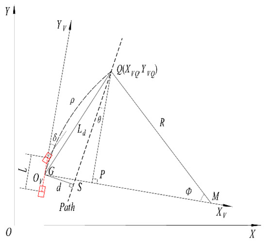
Figure 3.
The pure pursuit model of the transplanter.
In Figure 3, X–O–Y is the geodetic coordinate system, and YV–OV–XV is the rice transplanter coordinate system. XV and YV correspond to the abscissa axis and ordinate axis, respectively. The red line indicates the kinematic model of two-wheeler of the rice transplanter, and point G is the center of gravity of the two-wheeler model. The dotted line is the predefined driving path, and the starting point is at point G. ρ is the turning curvature of the rice transplanter; ρ > 0 is the curvature of the rice transplanter when turning counterclockwise, and ρ < 0 is the curvature of the rice transplanter when turning clockwise. R is the instantaneous turning radius of the rice transplanter. d is the lateral deviation of the actual position of the rice transplanter from the desired path; d < 0 means that the actual position is on the left of the desired path, d > 0 denotes that the actual position is on the right of the desired path. Ld is the look-ahead distance of the rice transplanter in the pure pursuit model, in which the distance can be regarded as the empirical value obtained by imitating the manual driving method. θ is the heading deviation between the current position of the rice transplanter and the path to the target position. M is the center of the rice transplanter moving along the curve of the turning arc. Φ is the heading change angle of the rice transplanter when rotating around the center, M, and reaching the target position along the turning arc. L is the wheelbase between the wheels before and after of the rice transplanter.
In accordance with the geometric relationship shown in Figure 3, the coordinates (XVQ, YVQ) of the target point Q in the YV–OV–XV coordinate system were defined as follows:
In the right triangle ΔPOVQ, the look-ahead distance and the coordinate value of the target point Q (XVQ, YVQ) satisfy the following relation:
According to Equations (1)–(3), the curvature ρ of the rice transplanter was calculated as follows:
Automatic steering is aimed at obtaining the desired rotation angle of the front wheel because of the rice transplanter with front wheel steering. Based on the pure pursuit model in Figure 3, the desired rotation angle and turning radius of the front wheel of the rice transplanter satisfy the following relationship:
where L denotes the front and rear wheelbase of the rice transplanter and δ indicates the desired angle of the front wheel.
According to the geometric relationship shown in Figure 3, Equation (1) could be rewritten as:
Under Equation (6), Equation (4) was rewritten as:
Combining with Equations (5) and (7), the desired rotation angle of the front wheel of the rice transplanter in the pure pursuit model could be calculated as follows:
3. Design of the Automatic Steering Control Algorithm
To enable the rice transplanter to follow the target path, it was ensured that the deviation between the actual driving path and the target path was minimized. Thus, the automatic steering system not only needed to grasp the current pose information of the rice transplanter accurately, but also realize the accurate steering. From the analysis of the kinematics model, the lateral deviation of the vehicle is caused by the heading angle, and there is a certain relationship between the change of front wheel angle and the heading angle. It can be concluded that tracking the control angle in real-time, based on the change of the front wheel angle, is the key to realize the automatic steering of the rice transplanter.
3.1. The Compound Fuzzy PID Control Algorithm
In an automatic steering control system, the control method plays a vital role in the overall control system. In this study, the PID control and fuzzy control theory were combined to design a compound fuzzy PID controller. The fuzzy controller is used to adjust the proportional, integral, and differential parameters of the PID online. The adaptive adjustment of the control system parameters can well adapt to the working environment. The schematic diagram of the compound fuzzy PID control is shown in Figure 4. First, the desired steering angle δ of the automatic steering front wheel was obtained, and the difference between the angle δ and the actual rotation angle was calculated, that is, the front wheel rotation angle deviation e. Second, the deviation conversion rate ec = de/dt was calculated. When e > 10°, the fuzzy controller was used to quickly adjust the deviation; when e ≤ 10°, the compound fuzzy PID controller was used to precisely adjust the front wheel angle [27].
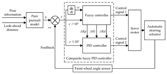
Figure 4.
Principle diagram of compound fuzzy proportional-integral-derivative (PID) controller.
As shown in Figure 4, the front wheel angle deviation e and the deviation change rate ec were taken as inputs of the compound fuzzy PID controller. The PID parameters ΔKp, ΔKi, and ΔKd are outputs of the controller. The PID parameters were adaptively adjusted online by the fuzzy inference method, which can meet different requirements of the different deviation e and the deviation change rate ec, so that the controlled object achieves the quantitative dynamic and static performance.
According to the compound fuzzy PID control principle, the compound fuzzy PID controller could be defined as follows:
where Kp0, Ki0, and Kd0 are the initial set values of the PID parameters and ΔKp, ΔKi, and ΔKd are the three outputs of the compound fuzzy PID controller.
3.2. Control Variable Fuzzification and Membership Function
As mentioned above, the front wheel angle deviation e and the deviation change rate ec are inputs, and the parameters ΔKp, ΔKi, and ΔKd are outputs. In this study, the conventional PID parameters were determined by an experimental trial and error method. Through closed-loop operation or simulation, the response curve of the system was observed, and the parameters were repeatedly tested, according to the influence of each parameter on the system. The PID control parameters were determined until a satisfactory response occurred, which were set as the initial parameters, Kp0, Ki0, and Kd0, of the compound fuzzy PID controller. The appropriate fuzzy domain was then selected, based on the parameters, and the parameters ΔKp, ΔKi, and ΔKd of the compound fuzzy PID control were determined by the fuzzy controller in real time. Based on the fuzzy control theory, the input and output variables were fuzzified as follows [27]:
- Front wheel angle deviation e. The basic domain is: [−30°, 30°], the quantification domain is: {−6, −4, −2, 0, 2, 4, 6} = {NB, NM, NS, ZO, PS, PM, PB}, and the quantization factor is: 6/30 = 0.2;
- Steering angle deviation change rate ec. The basic domain is: [−6, 6], the quantification domain is: {−6, −4, −2, 0, 2, 4, 6} = {NB, NM, NS, ZO, PS, PM, PB}, and the quantization factor is: 6/6 = 1;
- Proportional parameter ΔKp. The basic domain is: [−10, 10], the quantification domain is: {−3, −2, −1, 0, 1, 2, 3} = {NB, NM, NS, ZO, PS, PM, PB}, and the quantization factor is: 3/10 = 0.3;
- Integration parameter ΔKi. The basic domain is: [−8, 8], the quantification domain is: {−3, −2, −1, 0, 1, 2, 3} = {NB, NM, NS, ZO, PS, PM, PB}, and the quantization factor is: 3/8 = 0.375;
- Differential parameter ΔKd. The basic domain is: [−6, 6], the quantification domain is: {−3, −2, −1, 0, 1, 2, 3} = {NB, NM, NS, ZO, PS, PM, PB}, and the quantization factor is: 3/6 = 0.5;
With the high sensitivity of triangular membership function, they were selected as the membership function of the input variables, including e and ec and the output variables ΔKp, ΔKi, and ΔKd. The triangle membership functions corresponding to the input and output variables are shown in Figure 5.

Figure 5.
Input and output variable membership function: (a) Membership function of the input variables e, ec; (b) membership function of the output variables ΔKp, ΔKi, and ΔKd.
3.3. Compound Fuzzy PID Control Rules
In the compound fuzzy PID controller, the interaction between three parameters and their influences on other parameters must be considered. The tuning requirements of ΔKp, ΔKi, and ΔKd under different deviations |e| and deviation change rate |ec| are as follows [27]:
- When |e| is a small value, to maintain good steady-state performance of the system, ΔKp and ΔKi should be set as larger values, and the value of ΔKd depends on |ec|. When |ec| is small, ΔKd takes a larger value, whereas ΔKd should take a smaller value to avoid oscillation of the system.
- When |e| is a medium value, to reduce the overshoot of the system, the values of ΔKp and ΔKi should be smaller, and the value of ΔKd should be appropriate to speed up the response of the system.
- When |e| is a large value, to quickly reduce the system error and increase the reflection speed, the ΔKp value should be larger; ΔKi is often set to 0 to avoid the differential oversaturation caused by the instantaneous increase of the |e| value.
According to the tuning requirements above, the fuzzy control rules for PID control parameters were designed, as shown in Table 2, Table 3 and Table 4.

Table 2.
ΔKp fuzzy control rule.

Table 3.
ΔKi fuzzy control rule.

Table 4.
ΔKd fuzzy control rule.
According to the compound fuzzy PID control rule established above in Table 2, Table 3 and Table 4, the dynamic tunings of ΔKp, ΔKi, and ΔKd were obtained. The proportional, integral, and differential parameters of the PID controller, Kp, Ki, and Kd, could then be calculated by the following Equation (10):
where Kp0, Ki0, and Kd0 are the initial set values of the PID parameters.
4. Simulation Analysis
To verify the feasibility of the compound fuzzy PID automatic steering control algorithm, the simulation model of automatic steering control for the rice transplanter was established in MATLAB. The simulation model is shown in the Figure 6. In the simulation process, the front wheel rotation angle deviation e = 10° was set as the demarcation point, and the simulation analysis was performed when e = 8° and e = 25° [27], so that the compound fuzzy PID controller could adjust the parameters ΔKp, ΔKi, and ΔKd in real-time. The step signal response curves of the front wheel rotation angle deviation of 8° and 25° are as shown in Figure 7, respectively.
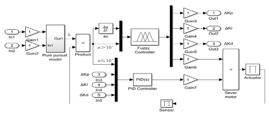
Figure 6.
Compound fuzzy PID control simulation diagram.
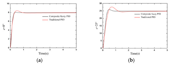
Figure 7.
Step signal response curve: (a) Simulation curve at 8°; (b) simulation curve at 25°.
The simulation analysis when the front wheel rotation angle deviation e is 8° and 25° is shown in Table 5. When the front wheel rotation angle deviation e = 25°, the response time of the compound fuzzy PID control was reduced by 0.23 s compared with the traditional PID control, and the overshoot was reduced from 3.5° to 1.6°. When e = 8°, the response time was reduced by 0.14 s and the maximum overshoot was reduced from 0.4° to 0.2°. It is noted that the compound fuzzy PID controller can speed up the response speed of the system, reduce the overshoot, and quickly reach a steady state, and the control effect is better.

Table 5.
Performance comparison of control algorithms.
5. Field Experimental Results and Discussion
5.1. Field Experimental Scheme
The field experiment was conducted at the Guohe Experimental Base of Anhui Agricultural University. The depth of the paddy soil was approximately 20 cm. The rice transplanter automatic navigation field experiment is shown in Figure 8. To evaluate the accuracy of the automatic steering control and robustness of headland turning, the field experimental tests included both linear tracking and headland turning. As shown in Figure 9, four parallel predefined paths with a length of 50 m and an interval of 1.8 m were set, namely A1B1, A2B2, A3B3, and A4B4, which were recorded as path 1, path 2, path 3, and path 4. Before conducting the autonomous driving experiment, the maximum steering angle, the net turning radius, and the maximum working width were measured as 45°, 1.0 m, and 1.80 m, respectively, by manually driving the rice transplanter. During the autonomous navigation operation, when the rice transplanter started to move from the point A1, the initial lateral deviation was +10 cm and the heading angle deviation was +3°. The compound fuzzy PID controller calculated the required steering angle in real-time and sent a steering command to the automatic steering system to realize automatic steering control. The experimental data, such as the pose information, speed, heading, lateral deviation, and heading deviation of the transplanter, were saved in real-time.
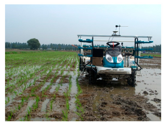
Figure 8.
Field experiment of automatic navigation operation.
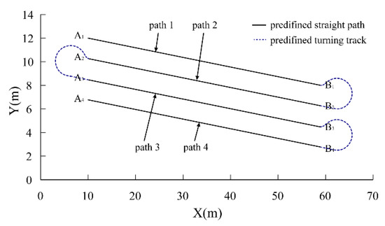
Figure 9.
Autonomous navigation predefined path.
5.2. Analysis of Experimental Results
Figure 10a shows straight tracking experimental results, where the red line is the actual trajectory. The corresponding lateral error and heading error were calculated and their deviation curves were shown in Figure 10b,c, respectively. From the deviation curves, it can be seen that the curves started out by fluctuating and then tended to be stable when the transplanter tracked the path along a straight trajectory. The lateral deviation and the heading deviation, respectively, fluctuated around 0 at the maximum of 7.50 cm and 3°. The average lateral deviations of the tracking path 1, path 2, path 3, and path 4 were for 3 cm, 2 cm, 2 cm, and 2 cm, respectively, and the average heading deviations were 1.9°, 1.8°, 1.8°, and 1.7°, respectively, which could meet the agronomic requirements of rice transplanting.
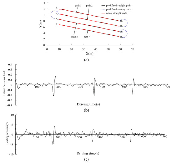
Figure 10.
Straight tracking results: (a) Straight track; (b) lateral deviation curve; (c) heading deviation curve.
In the field headland turning experiment, the turning radius of the transplanter was set to 1.20 m. Figure 11 shows the headland turning curve. The transplanter automatically turned in the headland of the paddy field when it drove to the end points, such as B1, A2, and B3, of three predefined paths. As shown in Figure 11, the tracking curve fluctuated greatly when turning and tended to be stable after headland turning. During headland turning, the lateral deviation and the heading deviation fluctuated around 0 at the maximum of 11.5 cm and 5°, respectively. The average lateral deviation was 4 cm and the average heading deviation was 2°. Most of the deviations were caused by the large slippage of the rice transplanter when turning at the headland of the paddy field. According to the field experimental results, the automatic steering control system with the proposed algorithm has a high tracking accuracy and sufficient robustness to meet the field performance requirements of the rice transplanter.
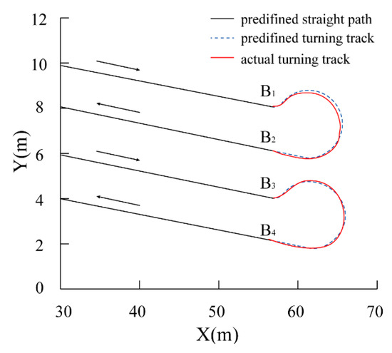
Figure 11.
Tracking curve of the headland turning.
6. Conclusions
In the manuscript, an automatic steering control algorithm, based on the compound fuzzy PID control, combining the fuzzy control, the PID control and the kinematics model of a rice transplanter, was proposed, and a compound fuzzy PID controller was developed. This controller can adjust the PID control parameters in real-time in the fuzzy domain, which can make the compound fuzzy PID controller output the best control variables. The automatic steering experimental platform was modified according to the compound fuzzy PID controller. Simulations and field experiments were performed to verify the effectiveness of the automatic steering control system. The experimental results showed that the maximum lateral deviations of the linear tracking and headland turning were 7.5 cm and 11.5 cm, and the average lateral deviation was less than 5 cm; the maximum heading deviation was 3° and 5° and the average heading deviation was within 2°. Both the lateral deviation and the heading deviation were within the allowable deviation range of field operation for the rice transplanter. In conclusion, the compound fuzzy PID control-based automatic steering algorithm developed in this study can realize the automatic steering control of the transplanter at different steering angles, effectively reduce the lateral deviation and heading deviation of the rice transplanter during the automatic navigation process, which is beneficial to improve the control precision of the automatic navigation, and can satisfy the agronomic requirements of the field operation of the rice transplanter.
Author Contributions
Methodology, J.Y.; Data Curation J.Y., J.L. and Y.W.; Validation, J.Y., J.L. and Y.W.; Resources, G.Z. and S.Z.; Writing—Original Draft Preparation, J.Y.; Writing—Review and Editing, J.Y., J.L. and D.Z.; Funding Acquisition, D.Z.
Funding
This work was supported by the National Key Research and Development Program of China (No. 2018YFD0700304), the Natural Science Fund of Anhui Province (No. 1708085QF148) and the Science Foundation of Anhui Agricultural University (No. 2016ZR008).
Acknowledgments
This work was supported by the National Project on Transformation of Agricultural Scientific and Technological Achievements No. 2014C30000162.
Conflicts of Interest
The authors declare no conflict of interest.
References
- Zhang, M.N.; Lu, X.L.; Tao, J.P.; Yin, W.Q.; Feng, X.B. Design and experiment of automatic guidance control system in agricultural vehicle. Trans. Chin. Soc. Agric. Mach. 2016, 47, 42–47. [Google Scholar]
- Ma, J.F.; Wang, D.C.; Tang, Y.W.; Zhao, J.B. Automatic control system of agricultural machinery based on Beidou navigation. In Proceedings of the IEEE 3rd Information Technology and Mechatronics Engineering Conference (ITOEC), Chongqing, China, 3–5 October 2017; IEEE: Piscataway, NJ, USA, 2017; pp. 318–323. [Google Scholar]
- Reid, J.F.; Zhang, Q.; Noguchi, N.; Dickson, M. Agricultural automatic guidance research in North America. Comput. Electron. Agric. 2000, 25, 155–167. [Google Scholar] [CrossRef]
- Torii, T. Research in autonomous agriculture vehicles in Japan. Comput. Electron. Agric. 2000, 25, 133–153. [Google Scholar] [CrossRef]
- Wang, X.C.; Lu, W.; Chen, M.; Wang, T.; Zhang, Y.; Boukangou, M.P. Automatic following system for greenhouse harvesting transportation based on adaptive pure pursuit model. Trans. Chin. Soc. Agric. Mach. 2016, 47, 8–13. [Google Scholar]
- Tang, X.T.; Tao, J.F.; Li, Z.T.; Li, Y.; Liu, C. Fuzzy control optimization method for stability of path tracking system of automatic transplanter. Trans. Chin. Soc. Agric. Mach. 2018, 49, 29–34. [Google Scholar]
- Elbanhawi, M.; Simic, M.; Jazar, R. Receding horizon lateral vehicle control for pure pursuit path tracking. J. Vib. Control 2018, 24, 619–642. [Google Scholar] [CrossRef]
- Quan, M.M.; Zhai, Y.; Jiang, Y.; Sun, Y.J.; Xu, D.L.; Gong, J.W. An Improved pure pursuit algorithm for four-wheel-steering autonomous driving vehicle. Appl. Mech. Mater. 2014, 3006, 958–962. [Google Scholar] [CrossRef]
- David, S.A.; de Sousa, R.V.; Valentim, C.A., Jr.; Tabile, R.A.; Machado, J.A.T. Fractional PID controller in an active image stabilization system for mitigating vibration effects in agricultural tractors. Comput. Electron. Agric. 2016, 131, 1–9. [Google Scholar] [CrossRef]
- Wen, S.; Zhang, Q.Y.; Deng, J.Z.; Lan, Y.B.; Yin, X.C.; Shan, J. Design and experiment of a variable spray system for unmanned aerial vehicles based on PID and PWM control. Appl. Sci. 2018, 8, 2482. [Google Scholar] [CrossRef]
- Sujaritha, M.; Annadurai, S.; Satheeshkumar, J.; Sharan, S.K.; Mahesh, L. Weed detecting robot in sugarcane fields using fuzzy real time classifier. Comput. Electron. Agric. 2017, 134, 160–171. [Google Scholar] [CrossRef]
- Bonadies, S.; Smith, N.; Niewoehner, N.; Lee, A.S.; Lefcourt, A.M.; Gadsden, S.A. Development of proportional–integral–derivative and fuzzy control strategies for navigation in agricultural environments. J. Dyn. Syst. Meas. Control 2018, 140, 061007. [Google Scholar] [CrossRef]
- Soares, F.T.; Cappelli, N.L.; Garcia, A.P.; Umezu, C.K. Fuzzy control applied to an electrical power generation system mounted on tractors for driving of agricultural implements. Eng. Agric. 2016, 36, 846–857. [Google Scholar] [CrossRef]
- Camci, E.; Kripalani, D.R.; Ma, L.; Kayacan, E.; Khanesar, M.A. An aerial robot for rice farm quality inspection with type-2 fuzzy neural networks tuned by particle swarm optimization-sliding mode control hybrid algorithm. Swarm Evol. Comput. 2018, 41, 1–8. [Google Scholar] [CrossRef]
- Csillik, O.; Cherbini, J.; Johnson, R.; Lyons, A.; Kelly, M. Identification of citrus trees from unmanned aerial vehicle imagery using convolutional neural networks. Drones 2018, 2, 39. [Google Scholar] [CrossRef]
- Eski, İ.; Kuş, Z.A. Control of unmanned agricultural vehicles using neural network-based control system. Neural Comput. Appl. 2019, 31, 583–595. [Google Scholar] [CrossRef]
- Duau, J.; Zhang, L.; Zhang, Z.; Zhao, J.; Jiang, Y. Research on Automatic Steering System of Agricultural Machinery Based on Fuzzy Neural Network. In Proceedings of the 2018 2nd IEEE Advanced Information Management, Communicates, Electronic and Automation Control Conference (IMCEC), Xi’an, China, 25–27 May 2018; IEEE: Piscataway, NJ, USA, 2018; pp. 1602–1605. [Google Scholar]
- García-Pérez, L.; García-Alegre, M.C.; Ribeiro, A.; Guinea, D. An agent of behavior architecture for unmanned control of a farming vehicle. Comput. Electron. Agric. 2008, 60, 39–48. [Google Scholar] [CrossRef]
- Remarka, M.; Griepentrog, H.W.; Nielsen, J.; Søgaard, H.T. The development and assessment of the accuracy of an autonomous GPS-based system for intra-row mechanical weed control in row crops. Biosyst. Eng. 2008, 101, 396–410. [Google Scholar]
- Nagasaka, Y.; Umeda, N.; Kanetai, Y.; Taniwaki, K.; Sasaki, Y. Autonomous guidance for rice transplanting using global positioning and gyroscopes. Comput. Electron. Agric. 2004, 43, 223–234. [Google Scholar] [CrossRef]
- Luo, X.W.; Zhang, Z.G.; Zhao, Z.X. The Method of Headland Turning in the Navigation Control for Wheeled Agricultural Machinery Compilation of the 2007 Annual Conference of the Chinese Society of Agricultural Engineering; South China Agricultural University: Guangzhou, China, 2007. [Google Scholar]
- Xu, L.L. Development of Tractor Automatic Navigation System Controller. Master’s Thesis, China Agricultural University, Beijing, China, 2011. [Google Scholar]
- Wang, F.X. Automatic steering control system for wheeled agricultural machinery. Agric. Eng. 2018, 8, 36–38. [Google Scholar]
- Qi, Z.J.; Yang, Z.G.; Huang, Y. Lane change track control for intelligent 4WS vehicle based on fuzzy adaptive PID. Chin. J. Autom. Eng. 2012, 2, 379–384. [Google Scholar]
- Xie, M.S.; Li, Y.N.; Zheng, L.; Pei, J.H. Synthesized feedback control of the ESP system based on fuzzy technology. J. Chongqing Univ. (Nat. Sci. Ed.) 2007, 30, 1–5. [Google Scholar]
- Li, G.; Wang, Y.; Guo, L.F.; Tong, J.; He, Y. Improved pure pursuit algorithm for rice transplanter path tracking. Trans. Chin. Soc. Agric. Mach. 2018, 49, 21–26. [Google Scholar]
- Zhu, G.Y. Study on Automatic Steering Control System of High-Speed Rice Transplanter. Master’s Thesis, Anhui Agricultural University, Hefei, China, 2018. [Google Scholar]
© 2019 by the authors. Licensee MDPI, Basel, Switzerland. This article is an open access article distributed under the terms and conditions of the Creative Commons Attribution (CC BY) license (http://creativecommons.org/licenses/by/4.0/).