1. Introduction
Steel offers many advantageous properties, including high strength and high resistance. Those properties make steel an almost ideal structural material. However, under fire conditions, steel properties deteriorate with exposure to elevated temperatures. This deterioriation leads to a decrease in the resistance of individual structural elements, which may result in a failure or collapse of the structure.
In a fire situation, the main priority is to protect human life. Next, the structure should be protected. These two goals are closely related. Improper protection of the building often prevents efficient evacuation of people, which may result in a calamity. Therefore, when a structure is designed, it must be provided with an appropriate fire resistance class to give people a long enough time to escape. All measures should be taken to reduce the risk of a structural collapse [
1,
2,
3]. Then, it is necessary to ensure that after the fire, the structure can still be brought back into use with minimum necessary repairs.
One of the most catastrophic structure disasters in history was the collapse of the Twin Towers of New York City’s World Trade Center. Media coverage created a public belief that the towers collapsed due to the impact of an aircraft. Numerous studies and expert opinions produced after the disaster, however, show that this impact was only an indirect cause. The impact of the aircraft caused a fire, which became a direct cause of the destruction of the towers [
4,
5,
6,
7,
8,
9]. Fires in the tall and high-rise buildings had happened before, but the September 11th disaster was the only one in which the steel skyscraper collapsed completely.
Some technical solutions that work perfectly well under normal conditions become a major disadvantage during a fire. In extreme situations, steel structures exposed to fire can disintegrate very quickly. This happened in Lubań, Poland, in July 2012, as a result of a fire in the production facility. The steel building, designed and made from thin-walled steel elements with a thickness not greater than 3 mm, collapsed in just 17 min [
10]. The use of cold formed structural elements has become more common in the construction industry during the past decades due to the various advantages cold formed structures offer, such as weight reduction of the structural system. The thin-walled sections differ from hot-rolled sections in terms of failure modes. In addition to local and global buckling, distortional buckling is also possible. The slenderness of steel members is a major factor in determining their failure mode at elevated temperatures. Short, stocky elements typically have a slenderness ratio less than 40, while for long, slender elements this value is greater than 120. The stocky columns exhibited local buckling as their failure mode, while longer, more slender columns displayed global buckling accompanied by limited local buckling. Problems related to the description of failure modes have been the subject of discussion in many works. Articles that deserve special attention include those in [
11,
12,
13].
The fire safety of steel structures does not only refer to buildings. Fires of bridges do not happen often, but if they occur, they produce serious consequences. The effects associated with a bridge being put out of operation are felt by a significant number of residents of the area and often the entire economy of the region. That was the case after the fire of the Łazienkowski bridge in Warsaw in February 2015. An average of 95,000 vehicles travelled daily over the bridge (about 18% of vehicular traffic on all Warsaw bridges). The initial expert report of the bridge’s technical condition showed degradation and a loss of carrying capacity in, among other elements, the steel structure of the bridge, resulting from elevated temperatures. [
14]. On February 20, 2015, the city authorities decided to dismantle the damaged steel structure of the bridge and mount a new one on the surviving pillars. The team from the Warsaw University of Technology, headed by Professor Zobel, conducted a detailed post fire inspection, which included materials tests, verification of the construction geometry and Finite Element Method (FEM) strength analysis [
15]. Experts found numerous additional defects, including dilatation damage, failure of the steel structure of the access walkway, damages to the road surface, protective barriers, paint coatings, and utilities. It was concluded that the main cause of damage was thermal shrinkage of steel. Due to various boundary conditions for individual elements of the bridge, a number of residual deformations occurred as the structure cooled. That resulted in selected elements being put out of operation. Finally, a decision was made to replace the steel structure of the spans using a modified incremental launching method. The bridge was opened on October 28, 2015.
The reported cases of fires that have occurred in recent years clearly indicate the need to improve the methods and means of increasing the fire safety of structures. The concept of fire safety is an extremely extensive issue. Ensuring an appropriate level of fire safety has been implemented in research and activities in several fields, especially mathematical, physical, and numerical modeling of fire phenomena. Another issue is the design of all types of fire protection, such as types of alarm systems or sprinkler systems, and the design of roads and evacuation systems in a manner ensuring maximum safety for building users. Fire protection covers all types of structures, due to the nature of the work, as well as the material used. Currently popular composite materials, such as concrete filled steel tube (CFST) columns, papers [
16,
17,
18], and polypropylene fibers [
19] are used in the area of the structures themselves. In contrast, the connections of load-bearing elements are modeled with the participation of a high-performance fiber reinforced cement composite (HPFRCC) [
13]. The HPFRCC high performance fiber-reinforced cementitious composite is a mixture of the correct proportions of Portland cement, fly ash, quartz sand, water, and polyvinyl alcohol (PVA) fibers. It is PVA fibers that have a decisive influence on improving the mechanical efficiency, elasticity, and durability of concrete structures [
20,
21] due to fire conditions. According to Li, Xu, Bao, and Cong [
22], PVA fibers under the influence of high temperatures melt to form channels to alleviate internal vapor pressure and thus explosive spalling. Therefore, the mechanical properties after a fire are higher compared to those of conventional concrete. In [
22], the authors performed experimental studies of four two-story and two-nave frames, two made of typical concrete (S1 and S2) and two in which the beam–column joint was made of high-performance cement composite reinforced with HPFRCC fibers (S3 and S4). The frames S2, S3, S4 were subjected to fire. The results of the tests carried out in the fire chambers showed that the application of HPFRCC increased the initial stiffness by 30%, the resistance and ultimate displacement by 6% and 3%, and the energy dissipation by 21%. In addition, only small surface flakes appeared at the HPFRCC joints, without the participation of explosive spalling on the HPFRCC. In works [
23] and [
24], as thermal insulation, polystyrene foam was used and in [
25], a portable compressed air foam system was used (regardless of its material of construction). An extremely important problem is the analysis of the static-strength response of structures in fire conditions [
26]. This paper focuses on this field and narrows it down to steel trusses. In steel structures, fire insulation is used in the form of intumescent paints or fireproof spray materials. The properties of these materials are discussed in other scientific articles [
1,
27,
28]. In this paper, thermal vermiculite mortar, vermiculite fireproof plaster with gypsum, protection in the form of vermiculite fire protection boards with cement, as contour insulation (for all types of cross-sections), and as box insulation (only for I-sections), were adopted as thermal insulation. In technical approvals of their products, the manufacturers of fire insulation recommend the adoption of a constant insulation thickness for all elements of the analyzed structure. However, such a solution is scarce (unprofitable). In this paper, we propose to carry out additional static-strength calculations in order to determine the optimal, required insulation thickness for each type of member truss.
3. Result and Discussion
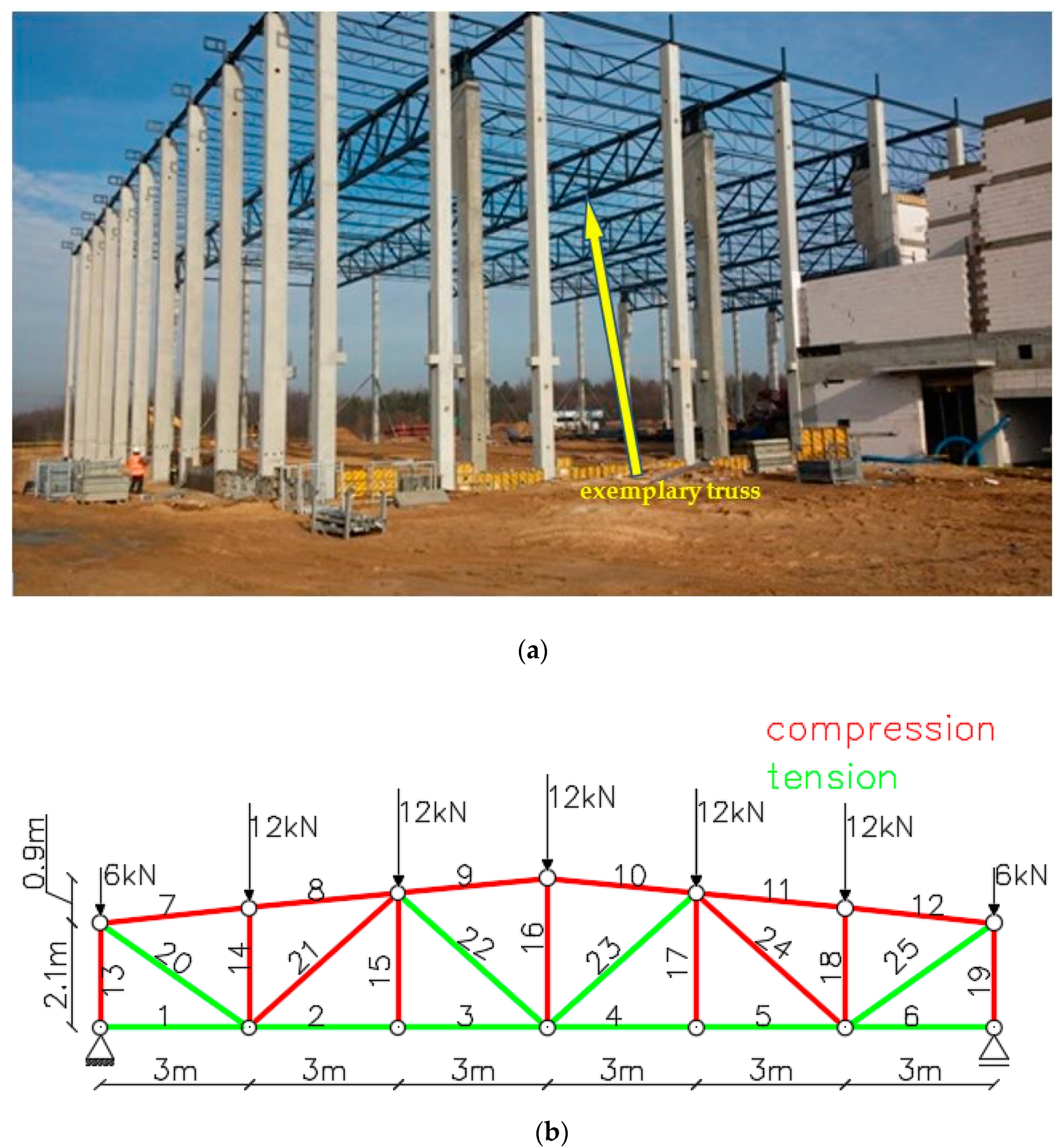
The structure shown in
Figure 1a is a steel, industrial hall with lattice girders pinned jointed to prefabricated reinforced concrete columns. The bracing system commonly used in this type of building makes it possible to model lattice girds as flat trusses (
Figure 1b). This approach is widely used in design practice. The connection of a steel lattice girder and a column is implemented as pinned. For this reason, it was assumed that the truss is simply supported. The system was loaded only with concentrated forces applied to the nodes of the top chord. In
Figure 1b, the compression elements are marked in red and the tension members are marked in green.
This structure was analysed with respect to basic and accidental (i.e., fire design) situations. It was assumed that all structural elements are made of S275 steel and heated from all sides. The top and bottom chords were made from I-sections, whereas bracing members were made from square tubing. The selected profiles and the effect of actions, i.e., forces arising in individual elements of the structure, are shown in
Table 2.
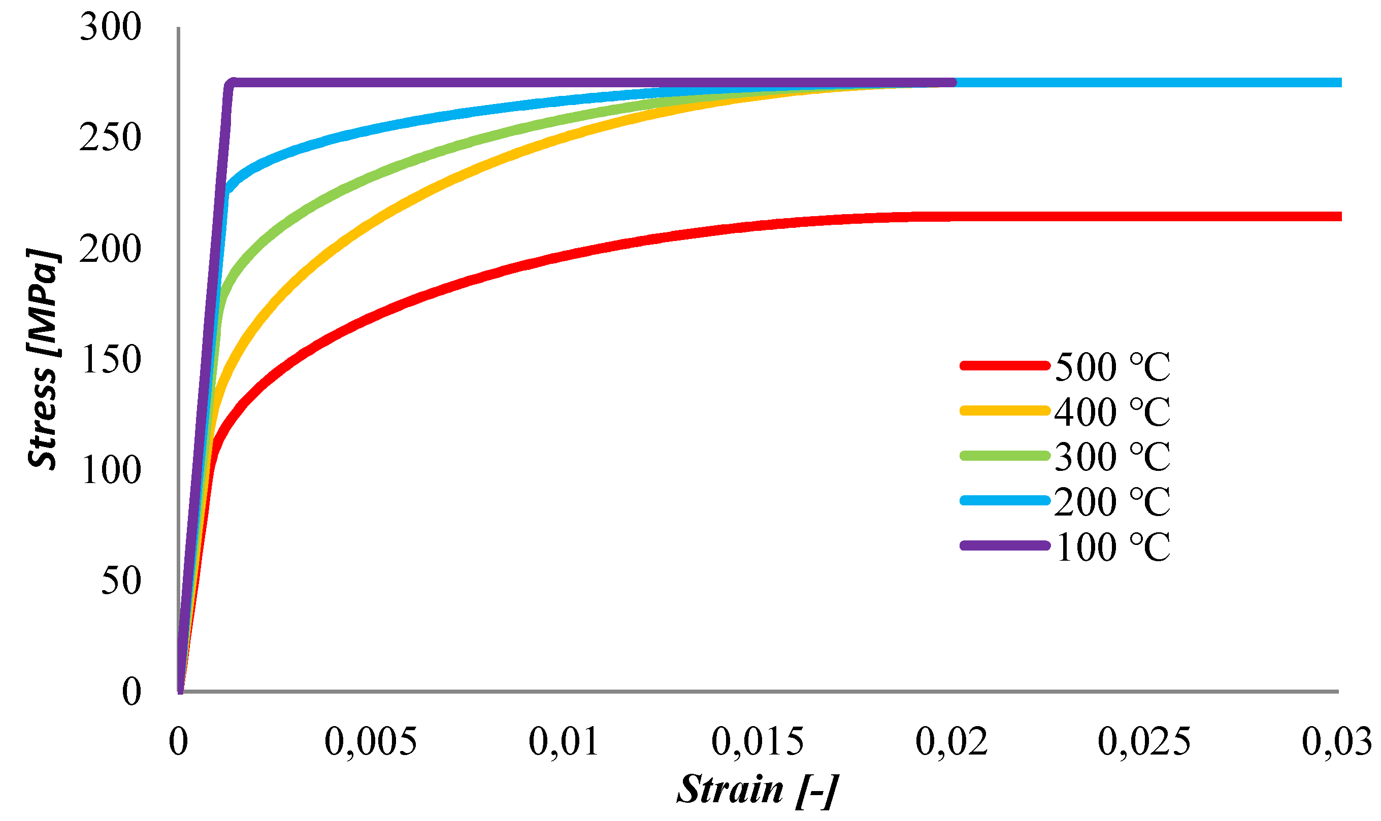
In the static analysis, by means of FEM, we used a flat truss element, which is a simple two-node element with two degrees of freedom in each node. The shape functions of the displacement field are linear. The displacement field of an element contains two translational components: horizontal u and vertical v. The strain tensor is reduced to one non-zero component of Green’s strain tensor
ε11, which characterizes the elongation of the bar. Other components of the strain’s tensor are equal to zero. The stress tensor is represented by component
σ11 of Pioli-Kirchhoff’s second stress tensor. The detailed mathematical formulations of the stress-strain relationship for steel at elevated temperatures are given in [
30]. In
Figure 2, this relationship is shown for steel S275.
The starting point of a full fire analysis is to define fire scenarios. It is assumed that the structure is in the fully developed fire phase, so the standard fire curve (Equation (1)) is adopted. For unprotected and insulated steel members, the temperature increment was estimated in accordance with the formulas in Equations (2) and (3). The temperature field is uniform along the member length and along the cross-section height. Next, the mechanical properties that influence the resistance of tension and compression members are calculated. The most important mechanical properties of steel elements are yield strength and Young’s modulus of elasticity. A decrease in the values of mechanical parameters leads directly to a reduction in the resistance of tension and compression members, as per Equations (5) and (6), which finally results in the limit state being exceeded. Thermal load is brought into the nodes as an additional load, in accordance with the incremental FEM method. For thermal load defined in this way, the stiffness matrix of the truss element is determined for Young’s modulus as a function of temperature.
The fire analysis is not intended to determine the value of the limit load but that of fire resistance, i.e., to specify the time of the structure’s failure. In this particular case, static loads are constant, whereas additional axial forces can be created in the truss elements under thermal load. Due to the fact that the structure is statically determinate, during the whole fire analysis, internal forces remain the same as in the basic situation. The computations, aimed at finding axial forces, strains, and displacements, are run with the MES3D program [
32,
33,
34]. The computations proceeded in two steps. The first step (20 °C) produced the specification of the state of the structure in a basic design situation. In the second step, temperature increments related directly to time steps, are taken into account. The analysis was repeated every second.
The simplest and most effective way to protect steel structures in the event of a fire is to isolate them from the influence of high temperature using the following protection [
35]:
Thermally activated (reactive) agents, e.g., swelling coatings;
Thermally passive means, e.g., spray masses and plate claddings;
Hybrid means combining plate claddings and spray masses.
Thermal properties of insulating materials change as fire develops [
28,
36,
37,
38]. However, the Polish standard [
29] allows adopting them as fixed values.
In this paper, fire analysis of the structure was carried out using three different types of thermal insulation with a thickness of 2 cm:
Protection with vermiculite fireproofing mortar;
Protection with vermiculite mortar with gypsum (high density);
Protection in the form of vermiculite boards with cement, as contour insulation (for all types of cross-sections) and as box insulation (only for I-sections).
The characteristics of the selected fire-proofing materials are listed in
Table 3.
Sprayed-on coatings are the most popular type of fireproofing insulation because of the many advantages they offer, including low thermal conductivity, low self-weight, cost-effectiveness, and simple installation [
28,
37].
Sprayed-on fireproofing pastes are produced in the form of dry mix, the ingredients of which are [
35]: cement- or gypsum-based binder, aggregate (e.g., vermiculite, perlite, mineral fibre, or mineral (rock) wool granulate), and modifiers.
Sprayed-on pastes can be applied in wet or dry technology. Currently, the most commonly used is a dry technology, consisting of transporting a pneumatically dry mix, which is combined with water or a liquid binder at the outlet end of the sprayer. Wet technology is less frequently used, i.e., mechanical application of water-mixed mixture using pump-spray units in a manner similar to machine plastering [
2,
35]. The all wet process involves dirt and wetting the surroundings. Fireproof spraying is performed based on the thickness in one or several layers, which are most often 2 or 3 layers. The thickness of the insulation from the spray masses ranges from 15 to 60 mm. The fire resistance class obtained with the participation of spraying fire-retardant masses is R15–R240.
Fireproofing protection of steel structure members can be provided using the following types of boards [
35]: rock wool, gypsum plasterboard, magnesium oxide-based, those that have gypsum or cement binder, those with cement and lime binders with reinforcement (most often a glass fibre one), and various types of filler materials.
Board insulations can be installed using different designs, namely contour or box configurations. In the first design, boards are fixed in such a way that the protected element cross-sectional shape is maintained. The other configuration involves the formation of the cuboid box, inside which the protected section is built-in.
Board claddings are aesthetically appealing, and they usually do not need additional finishing, but they provide a more expensive fire protection option compared with sprayed-on or intumescent coatings. Additionally, the time necessary for installation is much longer than for fireproofing coatings. That contributes to higher investment costs and extends the duration of the construction works [
1]. Board protection, applied as single or multilayer cladding, allows one to achieve fire resistance class R15–R240 [
35].
In accordance with Equations (2) and (3), the temperature increment in steel members also depends, among others, on the section factor. For sprayed-on contour board insulation, this factor is equal to the perimeter to the sectional area ratio. For box insulation, this factor is computed from formula [
29]:
where
b is I-section width,
h is section height, and
As is the cross-sectional area of the profile.
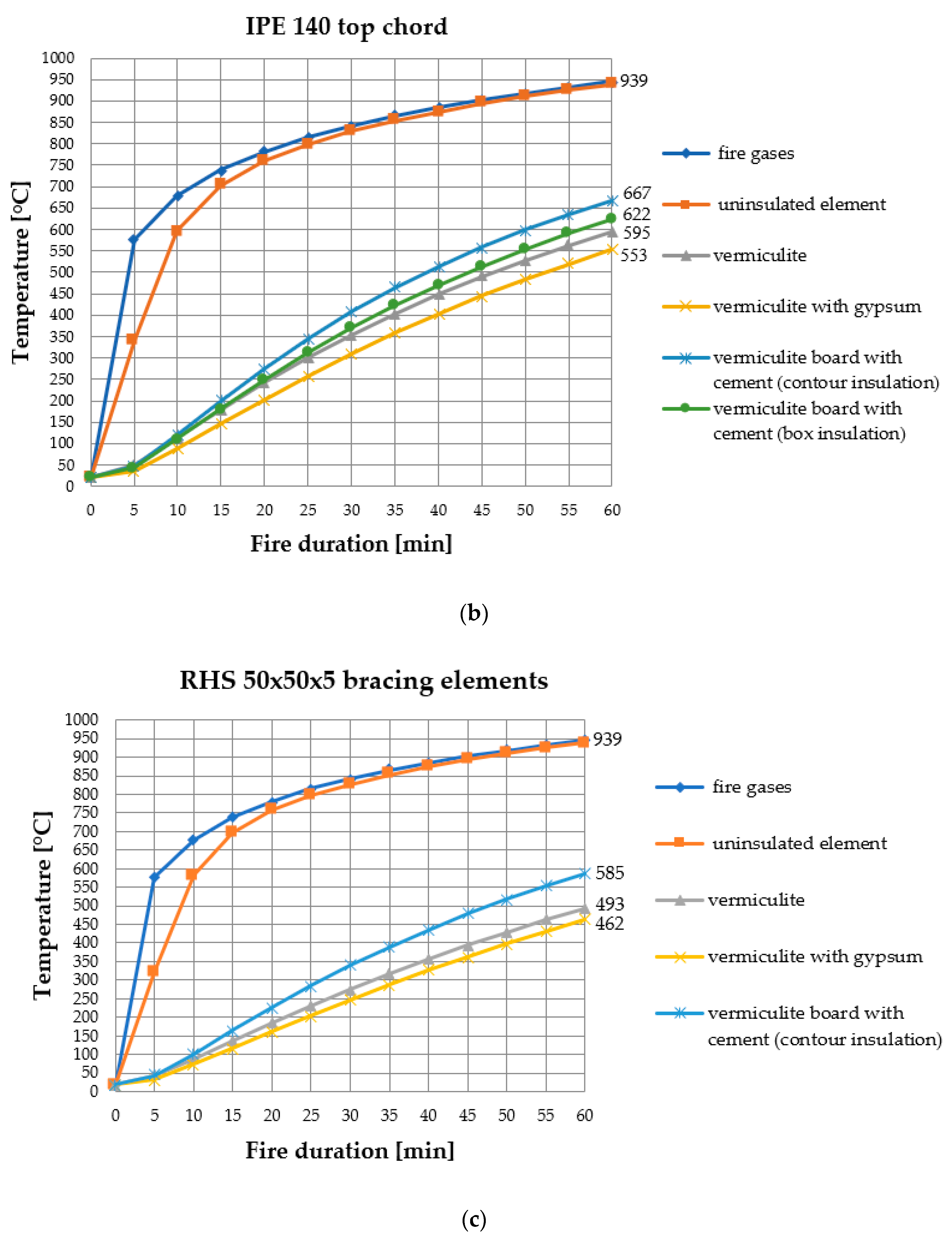
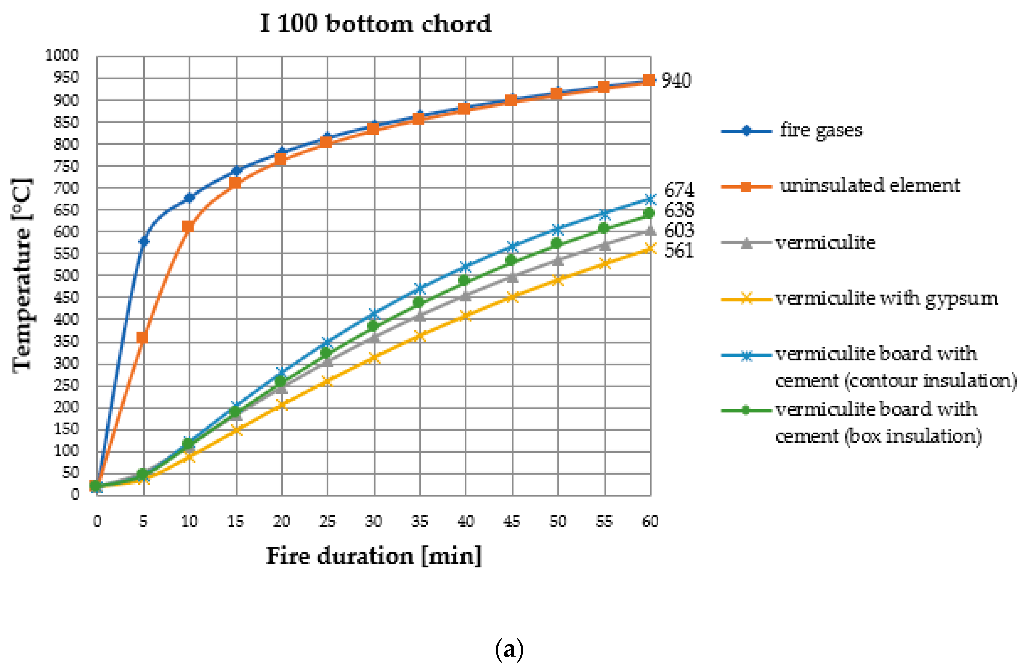
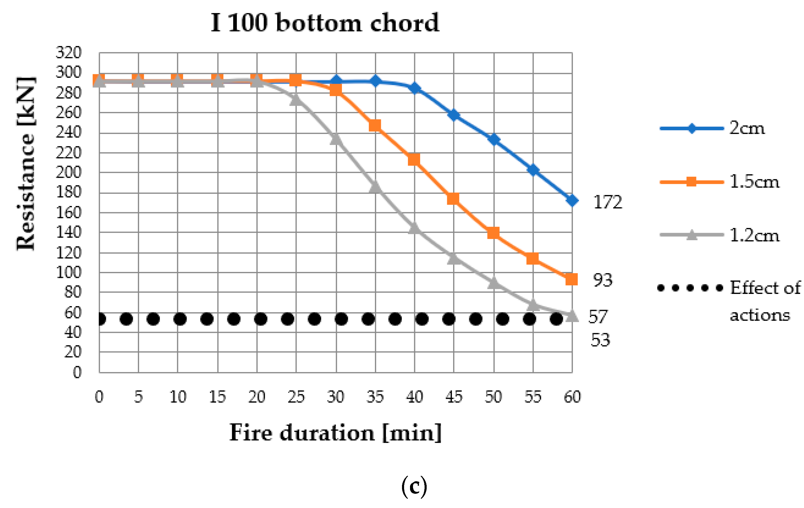
The highest section factor is found for the I100 section, used in the bottom chord. The value is equal to 349.057 m−1 for sprayed-on and contour board insulation. The value of box board insulation is reduced to 283.019 m−1. The top chord sections, namely IPE140, with box insulation show an exposure factor of 259.756 m−1 and 335.976 m−1 for other types of insulation. With respect to the bracing elements, made from square tubing RHS50x50x5, the exposure factor equals 214.204 m−1.
The temperatures of unprotected members, and the temperatures of all sections used in the experiment with different insulation types, are shown in
Figure 3.
The results presented above indicate that as the fire develops, the temperature of the members without fire-proofing insulation becomes closer to and, over time, equal to the temperature of fire gases. In such a situation, an abrupt fall in the modulus of elasticity and yield strength occurs, which results in a substantial reduction in the section resistance, leading to the exceedance of the ultimate limit state. Hence, further analysis involved only the members with fire-proofing insulation.
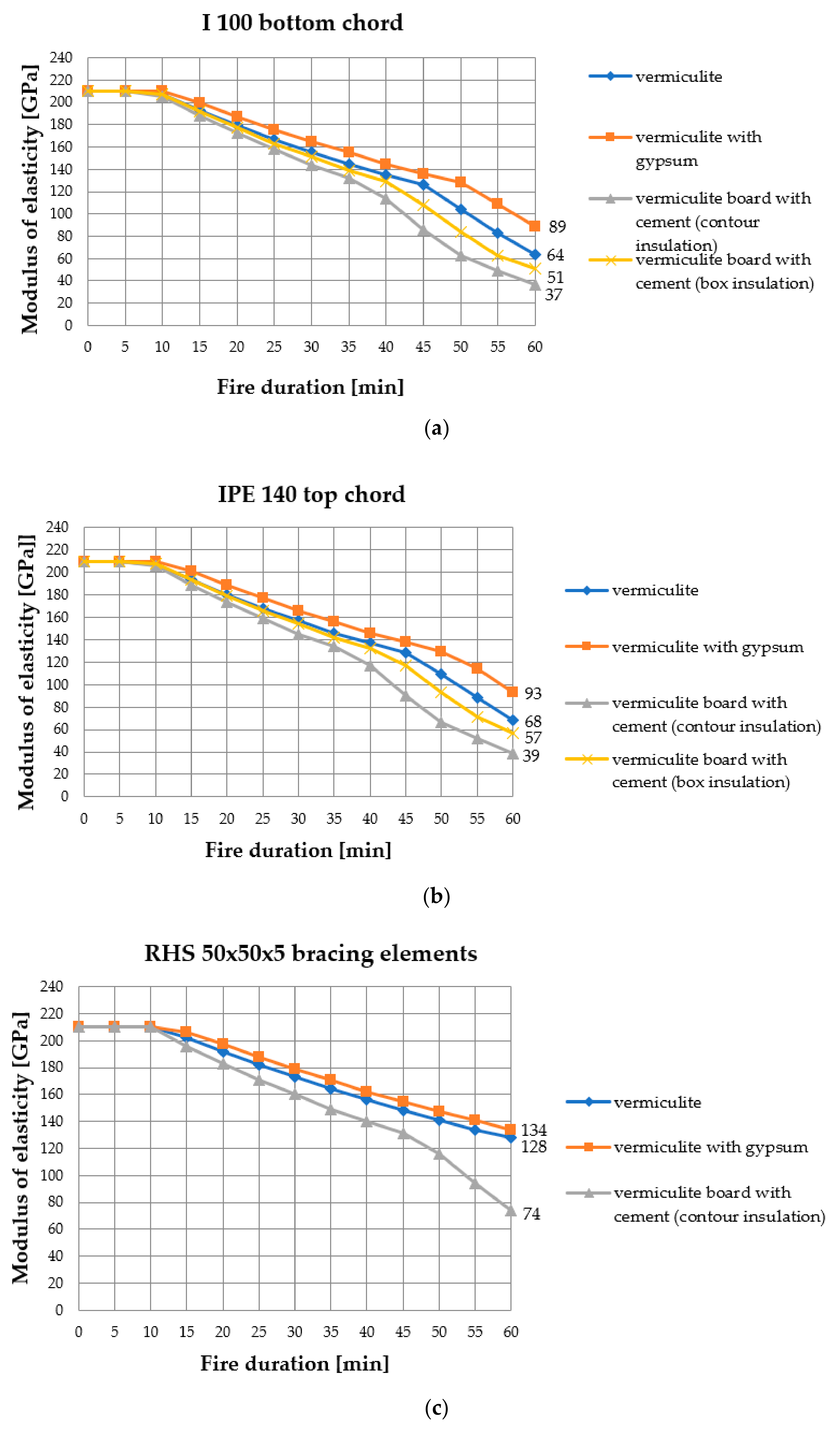
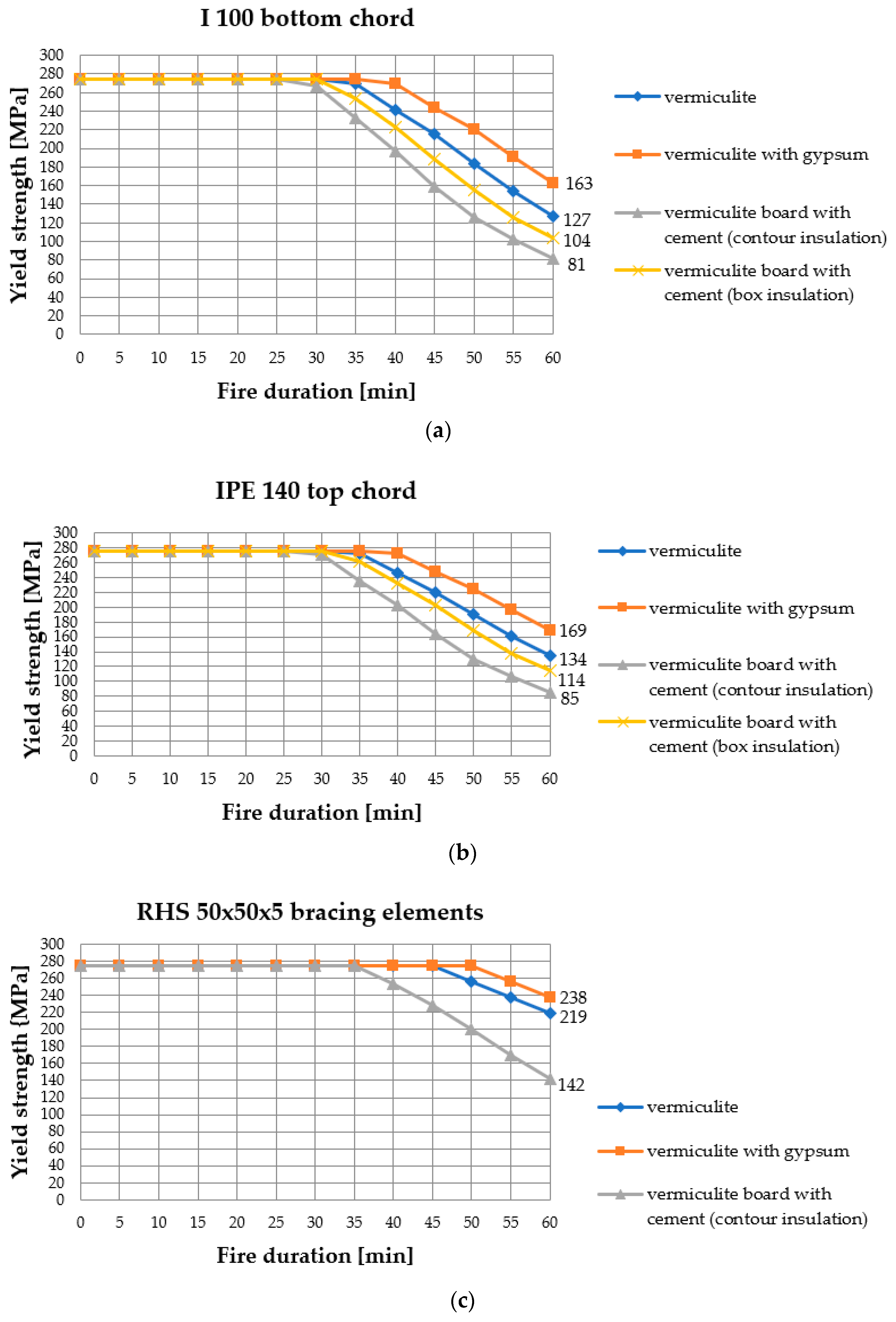
The thermal analysis was followed by the examination of the effect produced by different types of insulation on a decrease in the modulus of elasticity (
Figure 4) and yield strength (
Figure 5). The approach proposed in Eurocode [
30], namely reduction factors (
Table 1), was applied.
The truss in
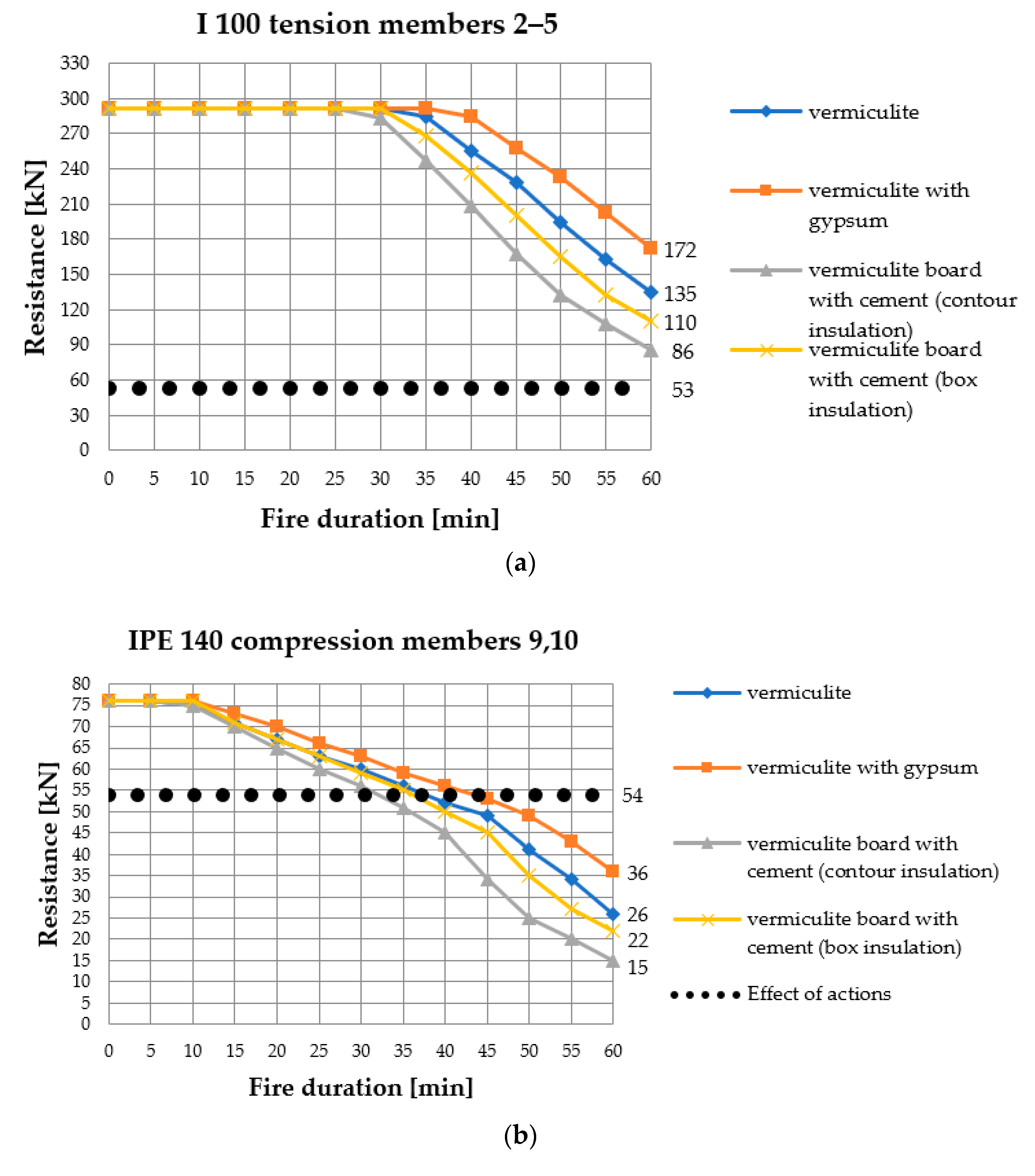
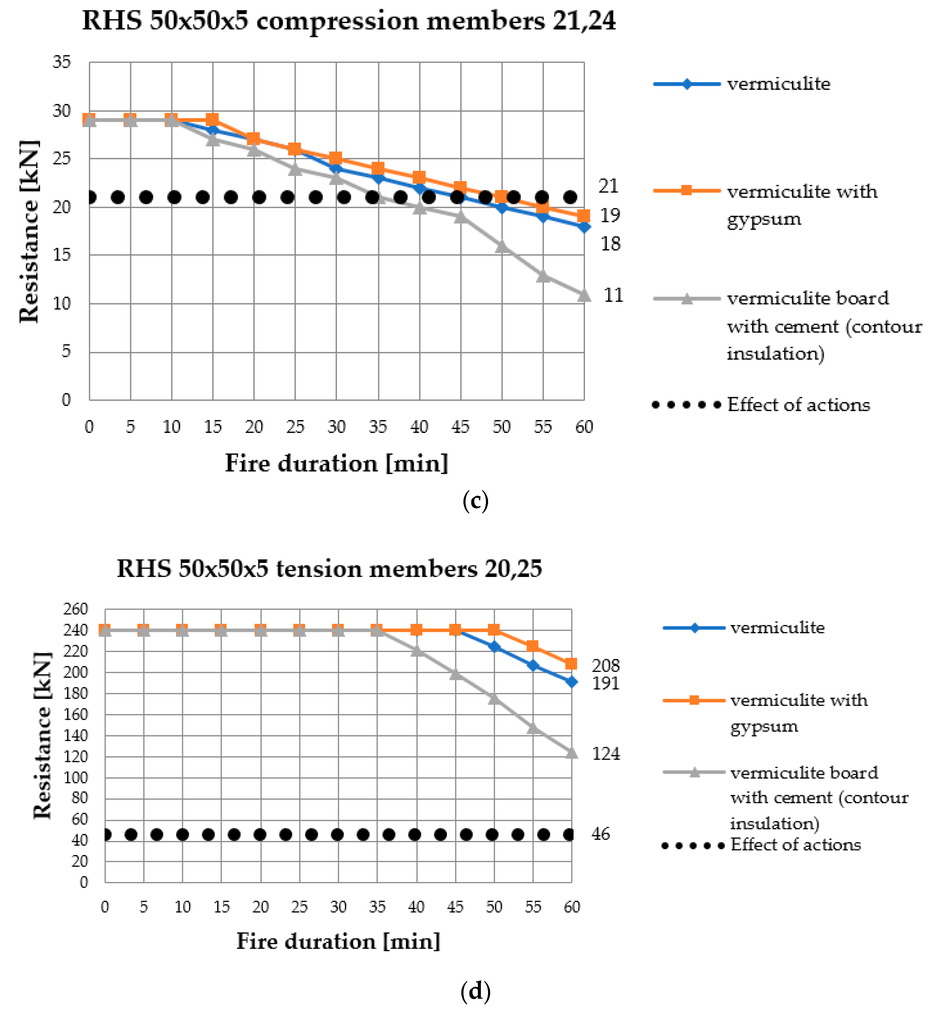
Figure 1b is statically determined. A serial reliability system is suitable for such a structure. In this case, the failure of one of the most stressed elements is equivalent to a failure of the entire structure. Therefore, the resistance analysis includes the most stressed elements of the truss. Tension members of the bottom chord from number 2 to 5 have the same resistance. The most stressed of the compressed top chord were elements 9 and 10. Next, the resistances of compressed members 21,24 and tension members 20,25 were calculated. The analysis results are shown in
Figure 6, in which the dotted line represents the effect of actions, i.e., internal forces arising in individual members due to the action of an external load.
Analysing
Figure 3,
Figure 4,
Figure 5 and
Figure 6, it is easy to notice that the best results were obtained by vermiculite with gypsum insulation. With this type of protection, steel members are heated up to the least extent value (
Figure 3), which corresponds to a slower decrease in the modulus of elasticity (
Figure 4) and yield strength (
Figure 5) and, consequently, produces a milder reduction in resistance in the successive minutes of the fire (
Figure 6). Slightly worse results were obtained using sprayed-on vermiculite insulation (
Figure 3,
Figure 4,
Figure 5 and
Figure 6). In terms of fire analysis, this means density is one of the major parameters. The higher the density, the better fire-proofing properties a material has. Another important property is thermal conductivity; conversely, the material should have the lowest possible thermal conductivity value. In this analysis, the worst results were observed when the insulation from vermiculite and cement boards was applied. The boards had the highest density of all materials under consideration, but their thermal conductivity was over 50% higher relative to the sprayed-on insulation (
Table 3). With vermiculite and cement boards, considerable improvements in results could be found using box insulation configuration instead of the contour one, which lowers the section factor. These results demonstrate that the lower the factor, the less heated up the element, which produces an advantageous effect on steel’s mechanical properties in fire. It should also be emphasised that differences in the results obtained for different types of insulation tend to grow as the fire develops. An adequate selection of fire-proofing insulation is of key importance for those members that require a high fire resistance class.
The diagrams in
Figure 6 indicate that the use of 2 cm fire insulation makes it possible to reach the fire resistance class R30 for compression and class R60 for tension members of the truss. This result means that elements of bottom chord and tension members are able to withstand 60 min of exposure to fully developed fire, whereas compression elements are able to withstand only 30 min. The fire resistance class of the whole structures is equal to the lower fire resistance class of any single element. So, with the assumed insulation, the structure reached the R30 class.
The analysis of the graphs in
Figure 6 clearly indicates a large capacity reserve in the tension elements. For instance, regarding the tension elements of the bottom chord, when 2 cm-thick vermiculite and gypsum insulation is used, the capacity of elements No. 2–5 after 60 min of fire duration is 172 kN, whereas the effect of action is 53 kN. That gives a reserve of 225%. A similar situation holds for the most stressed elements of the latticework, No. 20 and 25. After 60 min of the fire, their capacity is 208 kN while their effect of action amounts to 46 kN. Thus, the capacity reserve is 352%. Conversely, the performance of the compression elements is quite different.
Figure 6 again illustrates this result. It can be seen that the most stressed elements of the top chords, No. 9 and 10, have a capacity of 36 kN and an effect of action of 54 kN. As a result, their capacity is exceeded by 33%. For the compression elements of the latticework, No. 21 and 24, their capacity exceedance is 9.5%.
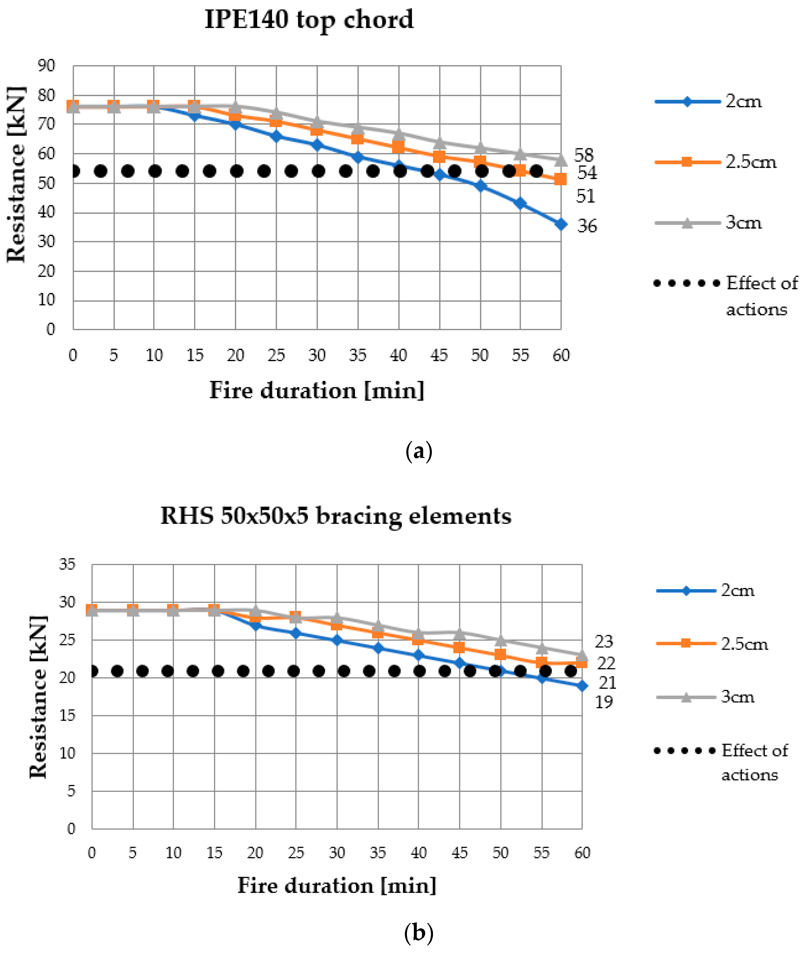
On the basis of
Figure 6, we can see that the commonly used method of constant insulation thickness is uneconomical. This paper proposes a differentiation of insulation thickness on truss elements. The best results were reached for the insulation of vermiculite with gypsum, so this material was used in the next analysis. The decrease of resistance during fire for different thicknesses of insulation is shown in
Figure 7.
According to charts in
Figure 7, the thickness of fire insulation was altered. For the top chord it was increased to 3 cm; for bracing elements it was increased to 2.5 cm. The insulation thickness of the tension elements of the bottom chord was decreased to minimum value of 1.5 cm (
Table 3) to reduce the costs of fire protection. Finally, the structure reached the R60 fire resistance class.


