Article

Fracture Resistance of Monolithic Zirconia Crowns on Four Occlusal Convergent Abutments in Implant Prosthesis

1
Division of Prosthodontics, Department of Dentistry, Kaohsiung Medical University Hospital, Kaohsiung Medical University, Kaohsiung 80708, Taiwan
2
School of Dentistry, College of Dental Medicine, Kaohsiung Medical University, Kaohsiung 80708, Taiwan
3
Division of Orthodontics, Department of Dentistry, Kaohsiung Medical University Hospital, Kaohsiung Medical University, Kaohsiung 80708, Taiwan
4
Department of Biomedical Engineering, I-Shou University, Kaohsiung 82442, Taiwan
5
Department of Materials & Optoelectronic Science, National Sun Yat-Sen University, Kaohsiung 80424, Taiwan
*
Author to whom correspondence should be addressed.
Appl. Sci. 2019, 9(13), 2585; https://doi.org/10.3390/app9132585
Submission received: 28 April 2019 / Revised: 20 June 2019 / Accepted: 21 June 2019 / Published: 26 June 2019

Abstract

:

Featured Application

Thicker and appropriately designed monolithic zirconia crown in the posterior implant area may have better fracture resistance even if the abutment needs to be milled to a convergent occlusal surface for a new insertion pathway.

Abstract

Adjusting implant abutment for crown delivery is a common practice during implant installation. The purpose of this study was to compare the fracture resistance and stress distribution of zirconia specimens on four occlusal surface areas of implant abutment. Four implant abutment designs [occlusal surface area (SA) SA100, SA75, SA50, and SA25] with 15 zirconia prostheses over the molar area per group were prepared for cyclic loading with 5 Hz, 300 N in a servo-hydraulic testing machine until fracture or automatic stoppage after 30,000 counts. The minimum occlusal thickness of all specimens was 0.5 mm. Four finite element models were simulated under vertical or oblique 10-degree loading to analyze the stress distribution and peak value of zirconia specimens. Data were statistically analyzed, and fracture patterns were observed under a scanning electron microscope. Cyclic loading tests revealed that specimen breakage had moderately strong correlation with the abutment occlusal area (r = 0.475). Specimen breakage differed significantly among the four groups (P = 0.001). The lowest von Mises stress value was measured for prosthesis with a smallest abutment occlusal surface area (SA25) and the thickest zirconia crown. Thicker zirconia specimens (SA25) had higher fracture resistance and lowest stress values under 300 N loading.

1. Introduction

Implant-supported fixed partial dental prosthesis is a popular treatment option for partially edentulous patients. The mean implant failure rate of fixed partial dentures in partially edentulous patients was reported to be 6% in both the maxilla and mandible (range: 1.9–12.5%) [1,2]. Conditions that contribute to restoration failure include cracking, chipping fracture, bulk fracture, excessive wear of the opposing tooth surface, excessive roughening of the ceramic surface, and unacceptable esthetics. Anusavice [3] defined restoration success as intact prosthesis survival with acceptable surface quality, anatomic contour, function, and esthetic. In clinical settings, delivering an implant prosthesis is challenging when the implant tilts during implantation, which may stem from anatomic limitation, unique treatment design (such as all-on-4), or other iatrogenic factors. Delivery methods of implant crowns mainly divide into the following: Cement-retained and screw-retained implant prosthesis. The implant abutment is always milled or custom-made to fit the insertion pathway.
Fixing a single implant prosthesis on a tilted implant fixture over the posterior area is often a challenging task due to limited insertion pathway, short interdental space, and difficult interproximal hygiene maintenance. After properly milling the implant abutment, one must put into consideration the ceramic materials used, prosthesis thickness, and repairing method after implant prosthesis failed in the future. The advantages of screw-retained implant prosthesis are easy retrieval, better tissue response, and capable of installing when interocclusal space is limited. On the other hand, delivering a cement-retained implant is easier than delivering a screw-retained implant. However, the clinician should evaluate the retention and resistance of the crown meticulously and clean excess cement after delivery.
Based on the method of fabrication, implant abutments can be classified into prefabricated and custom-made abutments. Prefabricated abutments are often used in the esthetic zones owing to difficulty in achieving a good emergence profile, and the margin of the abutment requires milling because it remains supragingival. The milling of prefabricated implant abutment is typically performed using high-speed handpiece and diamond dental burs [4,5]. The total occlusal convergence (TOC) [6], which is the convergence angle between two opposing axial walls, is one of the critical factors for the success of ceramic crowns. Low values of TOC [7,8], range 2° to 5°, are difficult for crown delivery and result in an increasing cement hydraulic pressure. High values of TOC [9], over 24°, are difficult to obtain proper retention of the crown in long-term follow-up. Owing to advances in software and hardware for the open computer numerical control (CNC) system development, computer-aided design (CAD) and computer-aided manufacture (CAM) have increased interoperability and dimension control when milling the implant abutment [10]. Designing abutment using software and milling metal/zirconia material have gained great popularity in clinical dentistry. These abutments have allowed the dentists to create individual emergence profile and provide an ideal structure and crown path insertion. After manual or machine milling, the morphology of the implant abutment can be adjusted, and the prosthesis is always set on an asymmetrical convergent angle of the axial surfaces which lead to different occlusal areas.
Zirconia is a crystalline form of zirconium dioxide; it has excellent mechanical properties similar to metal and with color close to natural teeth. The best properties for medical use are exhibited by zirconia stabilizing with Y2O3—also known as tetragonal zirconia polycrystal (TZP) [11]. A high flexure strength (900–1200 MPa) and compression resistance (2000 MPa) [12] render it suitable for use in clinical dentistry [13]. Monolithic zirconia crowns have gained popularity since 2010 [14,15,16], primarily for reducing the major clinical complications that resulted from the fracture of porcelain veneers and zirconia frameworks [17]. Lawn et al. [18] mentioned that failure mode, materials, flaw state, layer thickness, and cement may affect the fracture resistance of ceramic crowns. Deng et al. [19] showed that fully dense zirconia (Y-TZP) has the highest critical load (100–1000 N) at low thicknesses (0.1–1.0 mm) when comparing different ceramic specimens. Hamburger et al. [20] showed that the fracture risk of ceramic materials has a positive correlation to layer thickness. Weigl et al. [21] showed that 0.5 mm thick monolithic crowns possessed sufficient strength to endure physiological performance, regardless of the type of cementation. Lan et al. [22] showed that the mean fracture loading cycles of a 0.5-mm zirconia specimen is 8480 ± 2009. He recommended the use of an implant prosthesis of monolithic zirconia crown with a thickness of 0.8 mm during clinical practice. Additionally, Kelly [23] suggested a more relevant approach using the finite element method (FEM) to solve for stress as a function of load. Anatomically, axial loading posterior teeth with the implant prosthesis can vary from 42 to 412 N [24], and Raadsheer et al. [25] found that maximum voluntary occlusal force was 545.7 N in men and 383.6 N in women in natural dentition. On the other hand, Lan et al. [22] used 300 N to simulate the bite force of implant prosthesis of molar area. During maximum intercuspation (MICP), loading force would spread among all contacted teeth. Therefore, we anticipated that maximal voluntary occlusal force should not approach the value Raadsheer has presented.
As discussed above, the fracture resistance of monolithic zirconia specimens is primarily affected by the thickness [22], and researchers have attempted to determine the correlation between the different convergent occlusal area of implant abutment and breaking test of zirconia specimens after lead bearing. Therefore, the purpose of this study is to compare the fracture resistance and stress distribution of zirconia specimens on four different occlusal convergence implant abutments. The hypothesis is that more occlusal convergence of implant abutment would lead to less fracture resistance of monolithic zirconia crowns.

2. Materials and Methods

2.1. Specimens Preparation

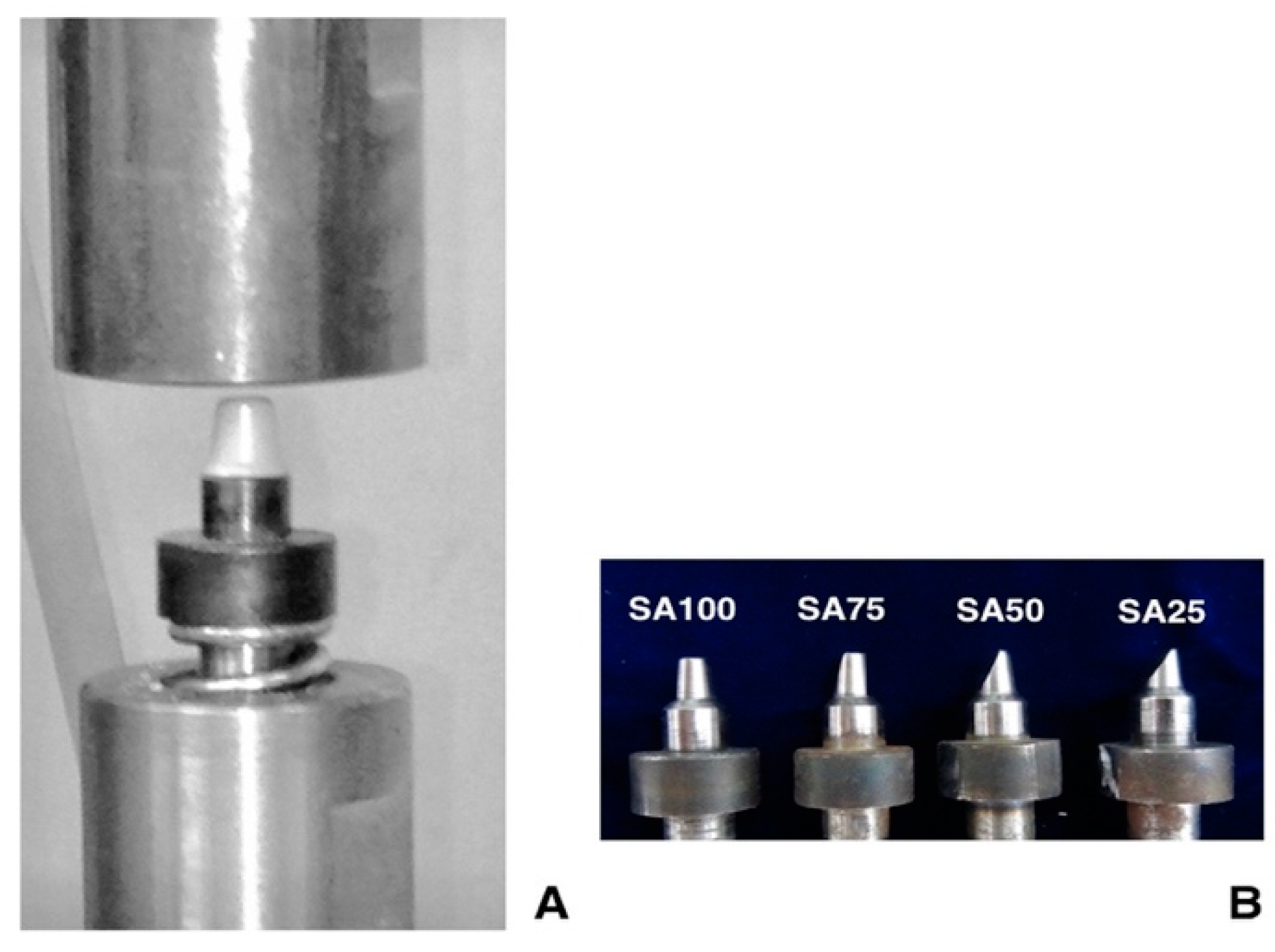
Figure 1 shows four implant abutments [occlusal surface area (SA) SA100, SA75, SA50, and SA25] in the molar area that were prepared to receive monolithic zirconia specimens. SA50 implies that the total occlusal surface contact area is half of SA100. The removed occlusal surface area (A) was calculated using the equation:
A = πr2 · θ/360 − 1/2 r2sinθ
where r is the radius of the circle; θ is the central angle measured in radians.
The specimen holder and the operating program of the test machine were adjusted to simulate the human masticatory cycle. The specimen holder had three parts: A precise adapter for the test machine, a heat-treated steel rod with a tapered tip to accommodate the specimen, and a spring to simulate cyclic occlusal contact and position control. The spring was checked before and after tests to verify the slope of strain and stress by Hooke’s law [26], as it should remain constant throughout tests. The G power analysis [27] was used to estimate the required sample size; assuming four test groups, an effect size of 0.56, the probability of an α error of 0.05, and power of 0.95. The sample size was set to have 15 per group. Overall, 60 complete zirconia specimens were designed using the computer-aided design/computer-aided manufacturing (CAD/CAM) technique to match the implant abutment design. The specimens were designed by the DentalCAD software (Exocad 2016, Exocad GmbH, Darmstadt, Germany). All specimens were milled from one commercial block of Y-TZP zirconia V (made in made in Bad Sackingen, Germany) using the same open CNC system milling machine (ARDENTA CNC MILL, CS100-5A, ARIX, Tainan, Taiwan) and were densely sintered at 1450 °C for 2 h.

2.2. Cyclic Loading Test

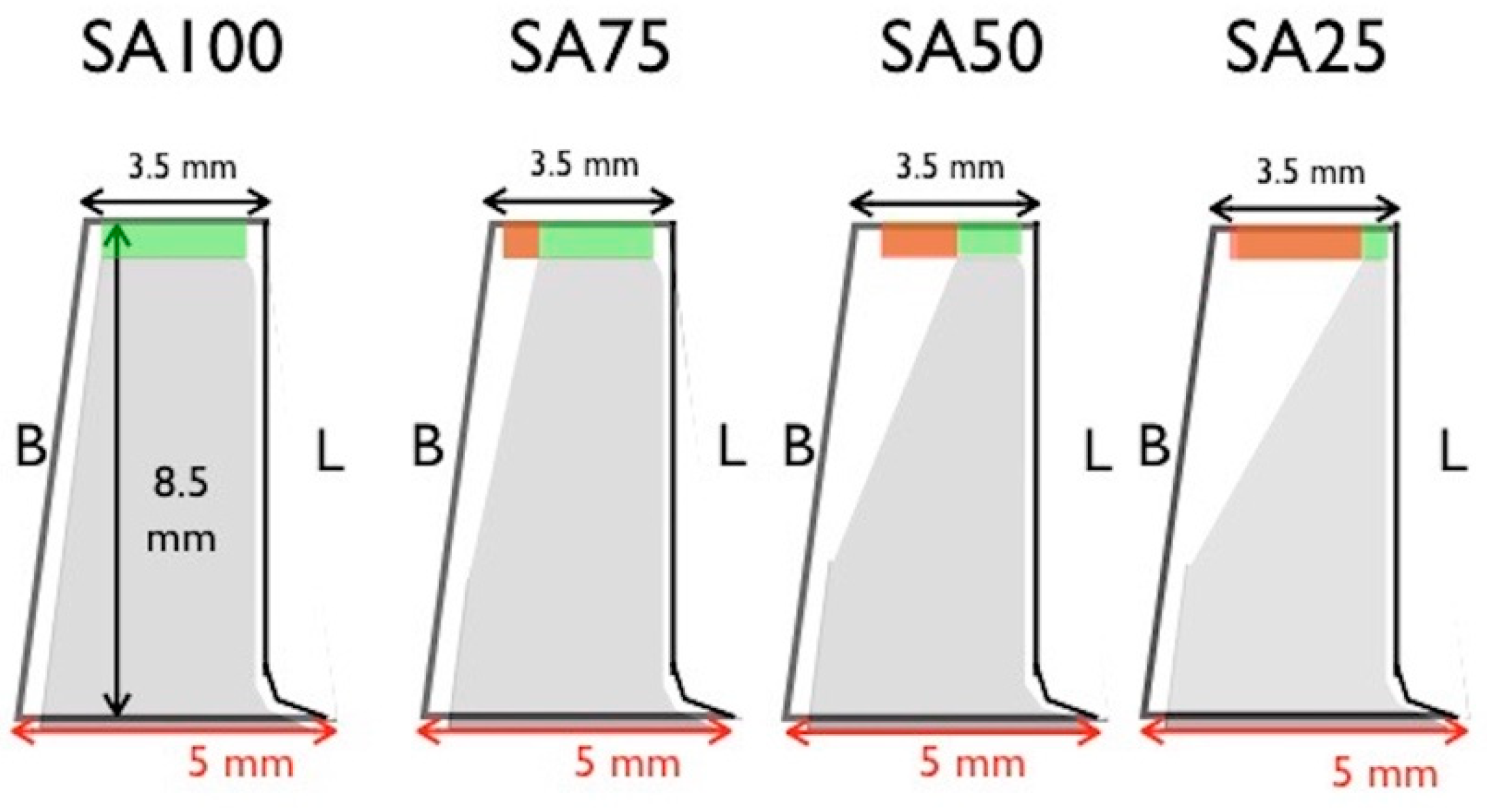
Figure 2 is the schematic representation of four implant abutment designs. The specimens were retained on the implant dies by friction and could only be removed by crown remover. The stability of the prosthesis was enhanced by the anti-rotation surface design of the dental implant abutment. The dimension of SA100 specimen was designed to fit the implant abutment with thickness of 0.5 mm over occlusal surface, diameter of 5 mm at base, and diameter of 3.5 mm at top. The reduction began 2 mm from the bottom to preserve retentive property, and tapered up to the desired occlusal surface area. Reduced volume was replaced with zirconia. Fifteen specimens in each group were tested vertically at 5 Hz and 300 N in a servo-hydraulic testing machine (Instron M8810, Instron Ltd. Norwood, MA, USA) until the specimen fractured or the test machine automatically stopped after 30,000 cyclic counts. To ensure that a consistent force was exerted on the specimen, the computer program had a 2-stage control to emulate the masticatory cycle of human jaw. The first stage, which simulated natural occlusal displacement, was position control. This stage ensured constant stroke distance between the load cell and specimen. The second stage was load control. This stage ensured a consistent force exerted by the load cell to the specimen remained constant throughout the test cycle.
The indentation stress-strain relation is well defined by the classic Hertzian theory for ideally elastic, homogeneous bulk materials with Young’s modulus E and Poisson’s ratio ν. The linear form of the Hertzian solution [28,29] is expressed as:
a = r d
p = 3F/2πa2
where a is the radius of the contact area, r is the radius of indent and d the depth, F is the loading, and P is the maximum contact pressure.

2.3. Finite Element Method

The dental implant abutment models were constructed using the CAD software (SolidWorks 2010, SolidWizard Corporation, Concord., MA, USA). Four finite element (FE) models with the different occlusal surface areas covered by zirconia specimens were constructed to simulate the posterior molar region. ANSYS was the FEM software used in this study (ANSYS Workbench 11, Canonsburg, PA, USA). The Young’s modulus and Poisson ratio of Ti-6Al-4V [30] were 110 GPa and 0.33, respectively. The Young’s modulus and Poisson ratio of zirconia [31] were 220 GPa and 0.3, respectively.
The materials used in the models were assumed to be isotropic, homogeneous, and linearly elastic. The average tetrahedral element size was 1 mm in length and the 3D FE model of SA100 model was meshed in the 115484 elements and 147842 nodes by convergence test. The 10-node tetrahedral element could provide six degrees of freedom (DOF), including three translations and three rotations on a node. Hence, total number of the DOF in the FEM was related to real nodal numbers. The boundary constrain of the bottom of the holder base would restrict the DOF of the implant-prosthesis complex of any rotational or translational movement. The mesh convergence test of element sensitivity was performed in this study before FEM. The convergence criterion was set to 5% to identify a reliable numerical result of the FEM.
The contact analysis in the contact area must be assumed that contact and target elements were paired to analyze surface interaction between two solid models under loading. Furthermore, the coefficient of friction must also be applied in the contact area. However, in this study, our main goal was to test the fracture resistance of different zirconia crown and implant abutment designs. Therefore, the sliding effect between the zirconia crown and implant abutment was considered negligible. For contact connection between the zirconia crown and implant abutment, we defined the finite element analysis (FEA) as a non-separating connection without any frictional effect. Hence, the contact analysis with frictional effect was not included in this study. Vertical loading of 300 N was applied on the occlusal surface of the specimens, and a 4-directional oblique force of 300 N at 10 degrees was applied to the marginal ridge of the specimens. The maximum von Mises (EQV) stress values were measured for specimens in different loading directions and implant prosthesis and abutment designs.

2.4. Statistical Analysis and Microstructural Observation

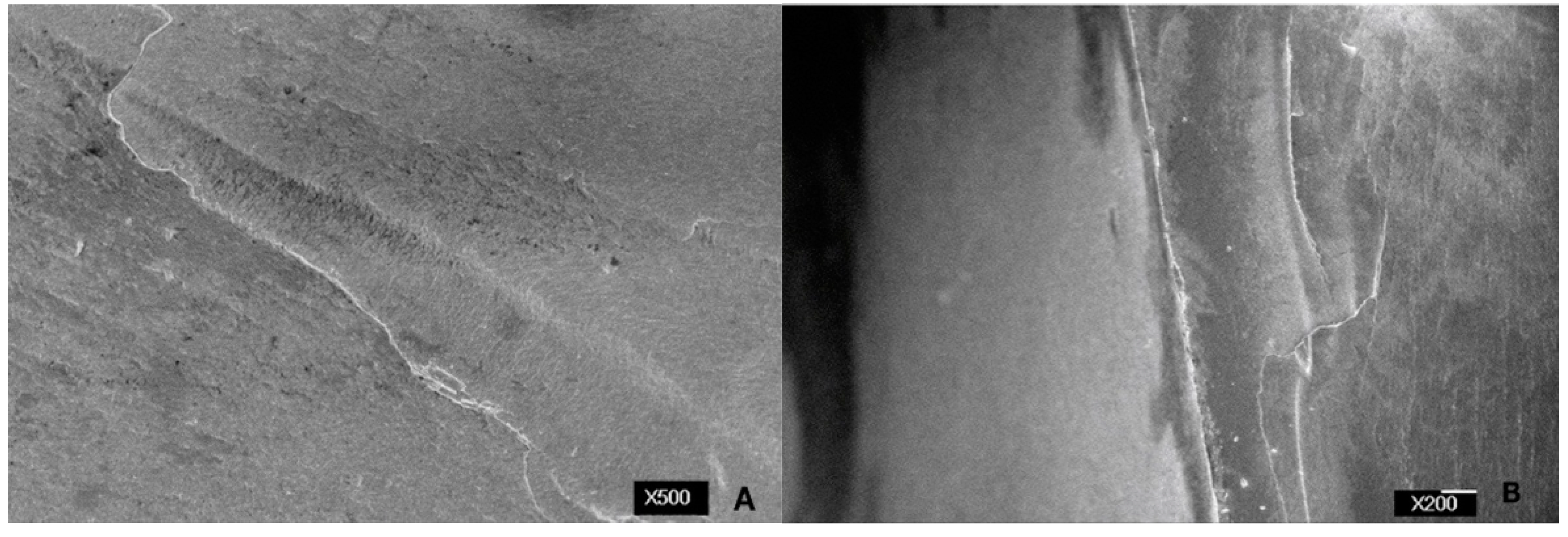
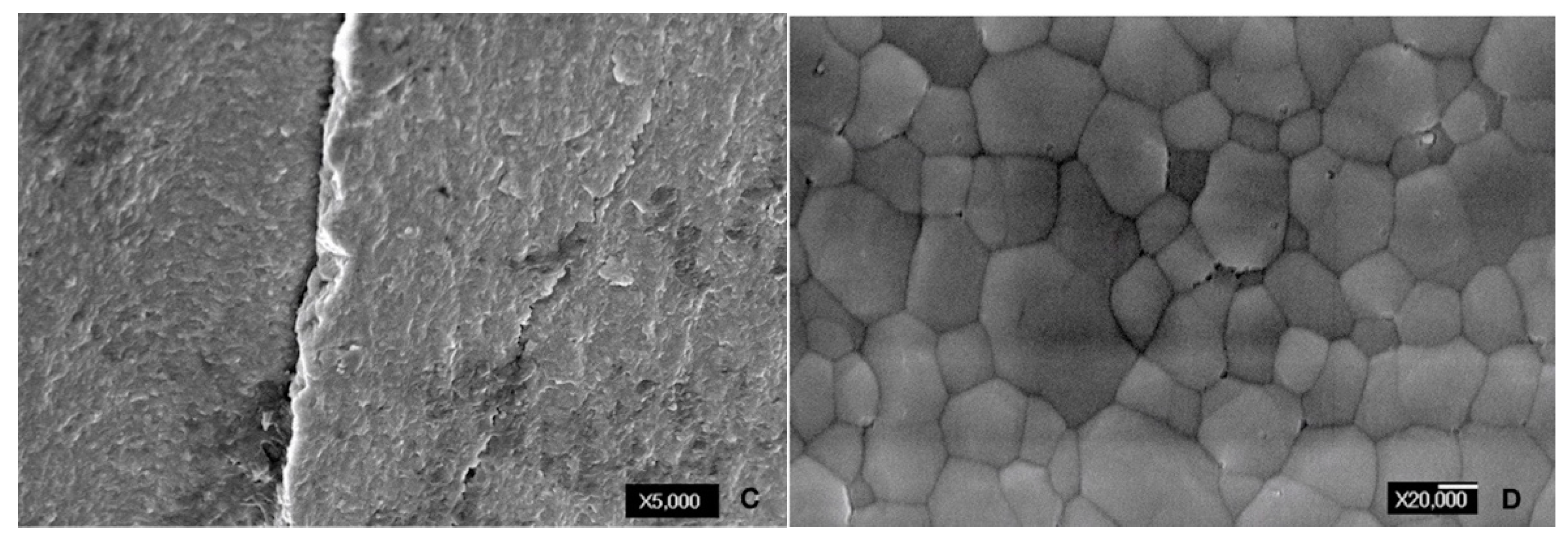
Data were normally distributed (P > 0.05) and there was no homogeneity of variance among groups of tests (P > 0.05). Data were compared using the Krukal-Wallis test, and the Spearman correlation was determined using a statistical program (SPSS Statistics for Windows, v20; IBM Corp, Armonk, NY, USA). Using scanning electron microscope imaging (JSM-6360; JEOL, Tokyo, Japan), the microscopic conditions of the specimens were examined.

3. Results

3.1. Cyclic Load Test

Table 1 showed the mean cyclic number and broken number/total number of specimens tested until fracture. The result showed 11061.6 (11/15), 12278 (6/15), 15617 (5/15), and 8000 (1/15) for the implant abutments with occlusal surface areas of SA100, SA75, SA50, and SA25, respectively.
The broken specimens of four occlusal surface areas showed specimens breaking into two to three fragments (Figure 3A–D). The cyclic number of broken specimens showed a significant difference among different groups of specimens (P = 0.001). Dunn’s honestly significant difference test indicated that the specimen breakage of SA100 was statistically significant when comparing to SA50 and SA25 (P = 0.001). Figure 4 showed that the percentage of intact specimens were 27% (SA100), 60% (SA75), 67% (SA50), and 93% (SA25), without visible fracture line found after 30,000 cycles. Specimen breakage had a moderately strong association with the implant abutment occlusal surface area (r = 0.475).

3.2. Finite Element Analysis

Figure 5 was a cross-section view of the SA25 model experiencing vertical loading of 300 N. The stress was transmitted from the specimen to the implant abutment and the maximum stress value was shown on the lingual edge of the specimens. Figure 6 and Figure 7 showed that stress was concentrated around the corner area on the occlusal axial wall of the specimens where forces were applied vertically or obliquely. The maximum EQV was higher under oblique loading compared to vertical loading. Figure 8 compared the maximum EQV value of four implant abutment designs under vertical and oblique 10-degree 300 N loading. The results showed that the peak EQV of SA25 had the lowest value compared to the other three types. Oblique lingual loading had the lowest peak EQV out of all oblique loading directions. The percentage of fracture specimens among the four groups was positively associated with the results of FEA (r = 0.391).

3.3. Microstructure of Zirconia Block After Cyclic Loading Test

Figure 9 showed the microstructure of the fractured zirconia segment after loading when viewed with scanning electron microscope (SEM). The SEM images in Figure 9A showed beach marks, which indicated the progressive fatigue failure of the zirconia specimen. Figure 9B,C revealed an apparent fracture line visible alongside the beach marks when a brittle failure of the material occurred. Figure 9D showed full densification and sufficient sintering of the zirconia and presence of some small pores at grain and grain boundaries.

4. Discussion

Lan et al. [
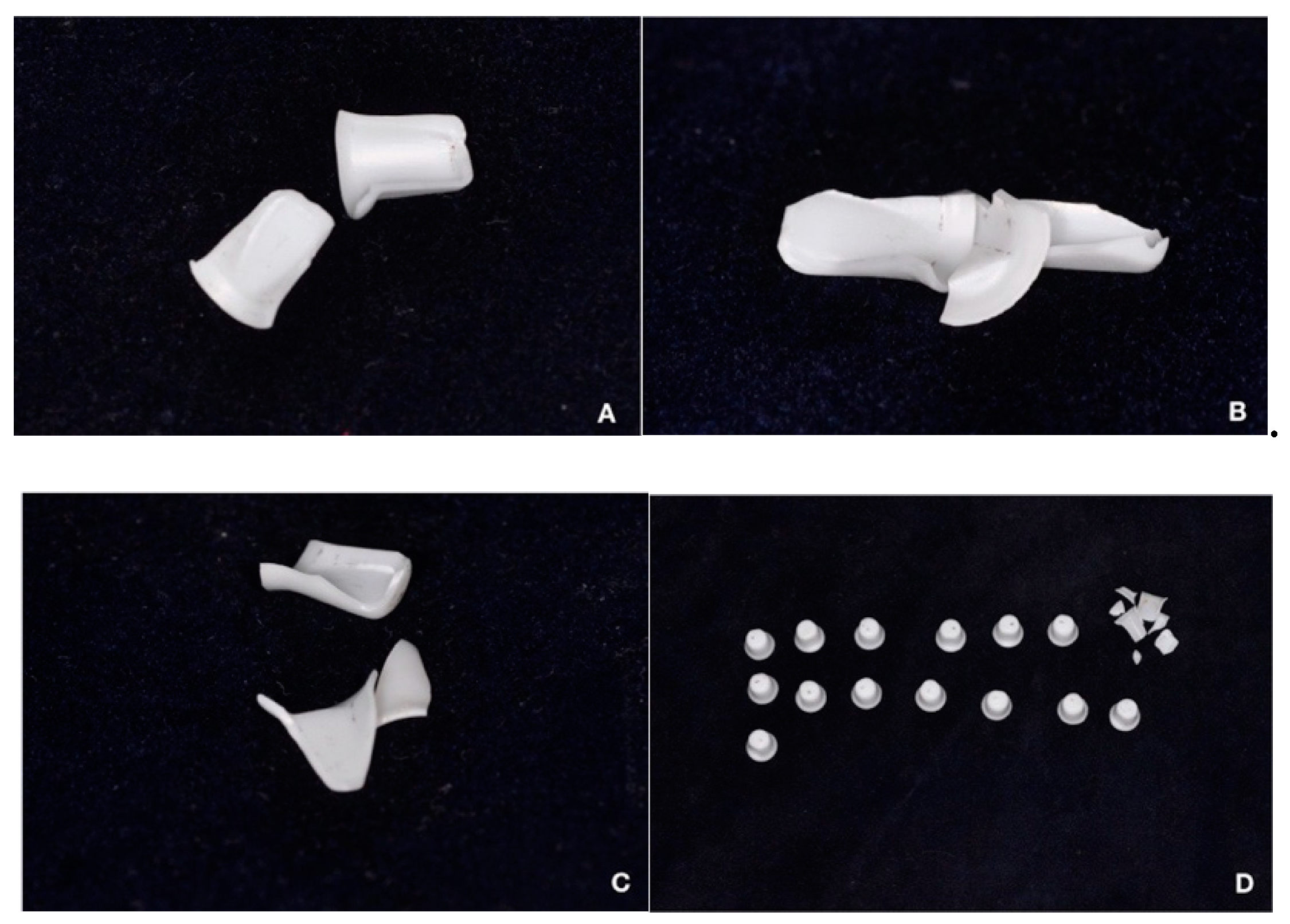
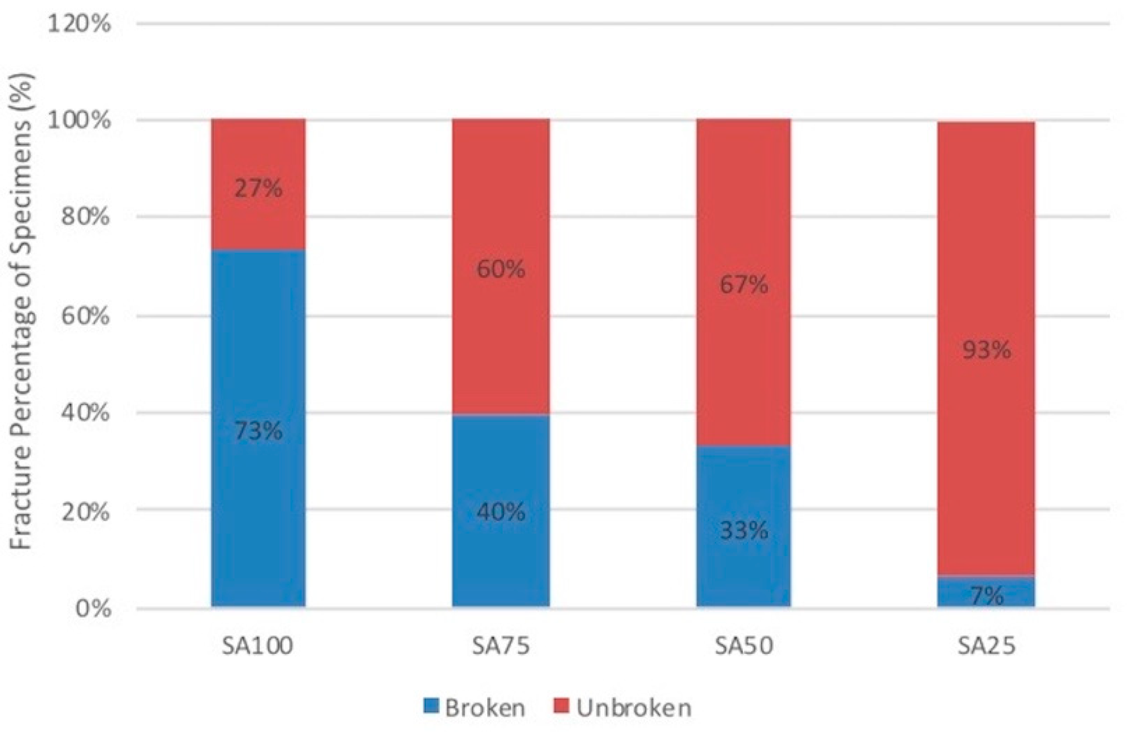
22] found that the fracture resistance of zirconia specimens have positive correlation with prosthesis thickness, and the mean cyclic number of broken specimens on 0.5 mm thickness was 8480 ± 2009. This study demonstrated breakage in 11 of 15 specimens (73%) and a similar cyclic number of broken specimens for 0.5 mm (SA100) zirconia specimens (Table 1). In addition, the breakage percentage of SA75 specimens (6/15) showed no statistical significance (P > 0.05) compared to SA50 specimens (5/15). On the other hand, only one SA25 zirconia specimen (1/15) broke during 300 N vertical loading. The results supported the speculation that the implant abutment occlusal surface area affects the fracture resistance of the zirconia crown, although only a moderately strong correlation was found (
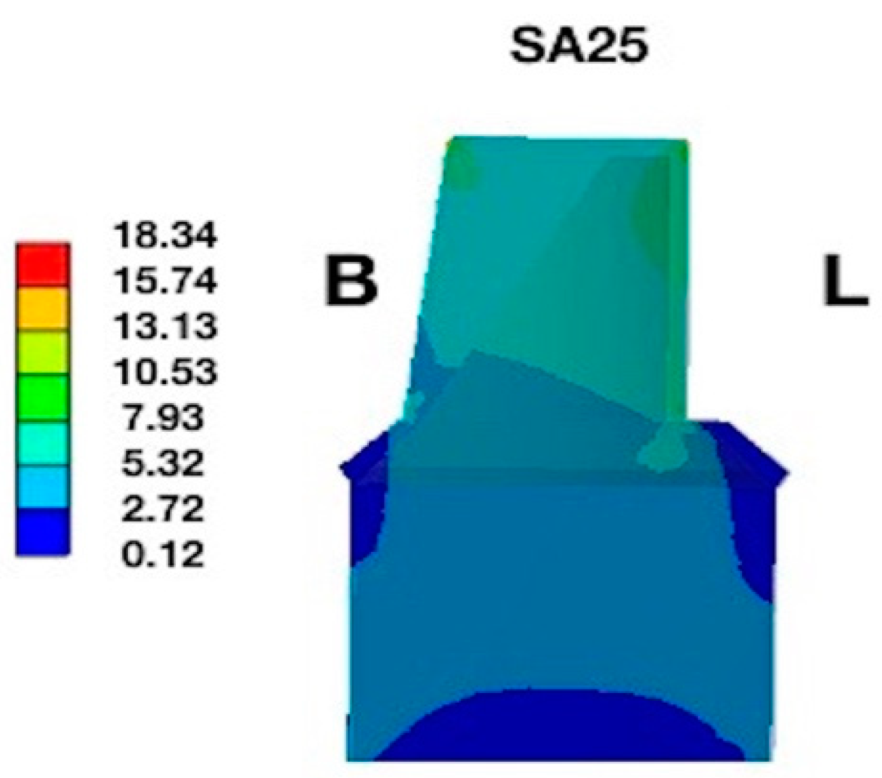
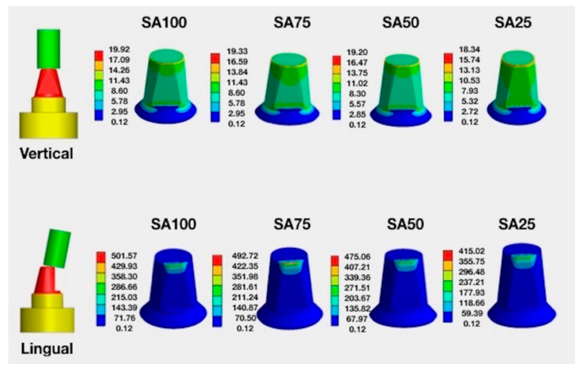
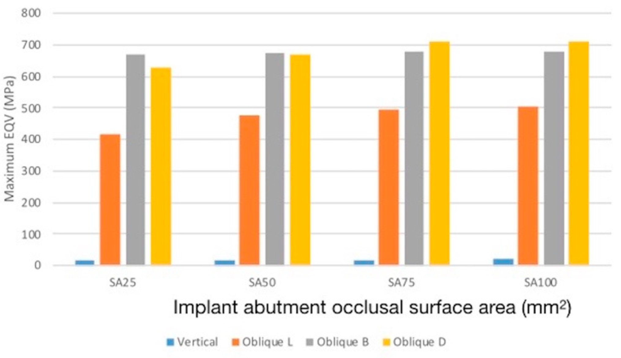
r = 0.475). The FEM showed the lowest peak stress value for SA25 specimen in all loading types, hence, we speculated that the implant abutment occlusal area has an inverse proportion to fracture resistance of the zirconia specimens (Figure 1 and 
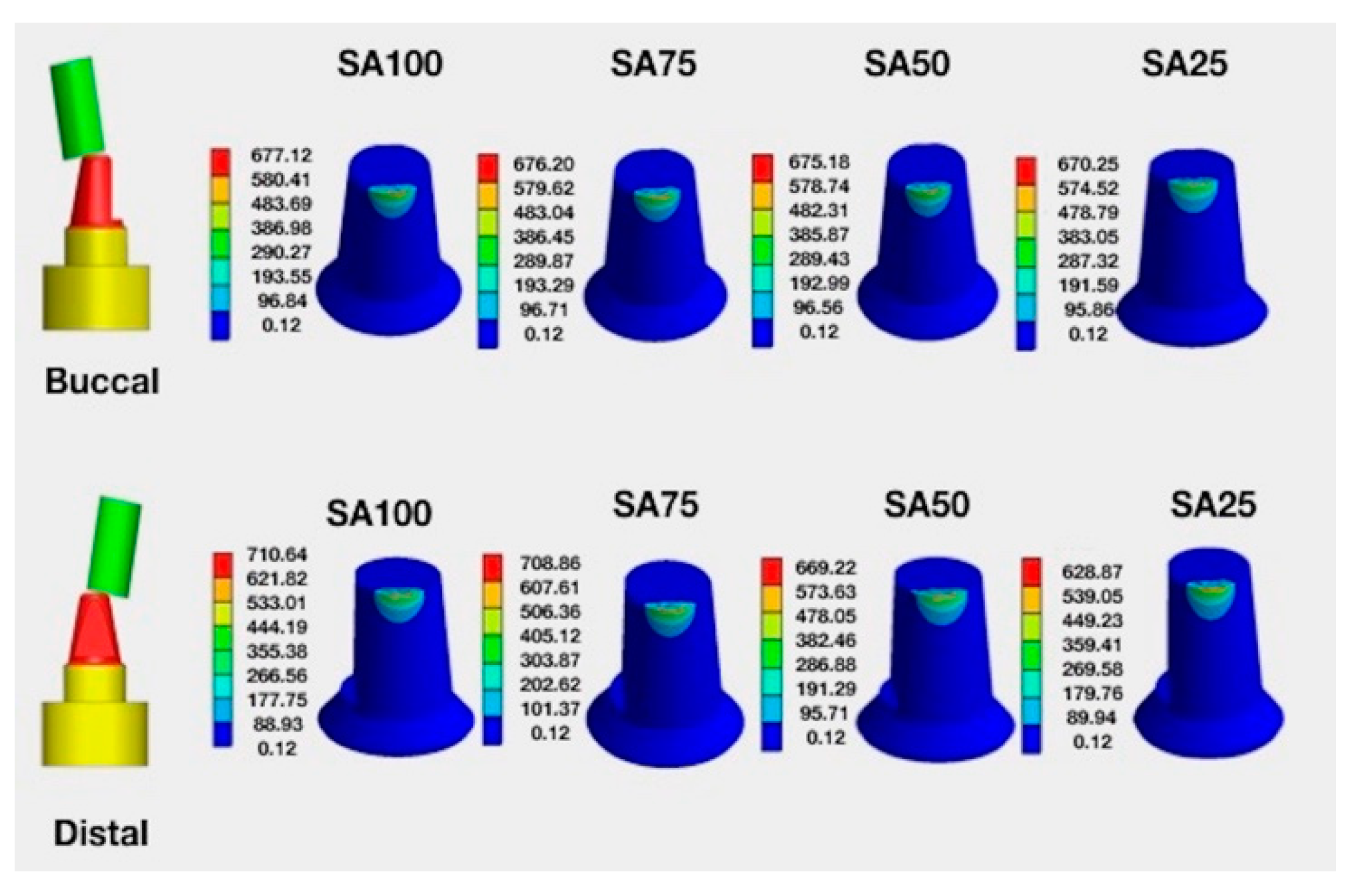
Figure 2). Under oblique loading, the peak value of the crown from the lingual side was lower than that from the buccal and distal side. This difference was attributed to the contact area of the prosthesis because the radius of the contact area from the lingual side was greater than other surfaces (Figure 5 bottom row). Moreover, the radius of the contact area negatively affecting the stress under constant loading is clarified by the Hertzian theory [28,29]. On the other hand, the oblique buccal loading and oblique distal loading showed similar peak stress, which may be attributed to the same contact area between the indenter and zirconia crown (Figure 6 top and bottom row).
Cyclic loadings could cause an accumulation of deformation and decrease the load resistance of the tested materials. Static loadings were loads with a very low rate of change to maximum stresses on specimens. Studart et al. [32] showed the cyclic fatigue behavior of zirconia at loads between 50 and 200 N and indicated that zirconia can tolerate the severe cyclic loading in the molar area. On the other hand, static FEM analysis was shown the maximum stress value and stress distribution from an applied load 250 N on the specimens. For brittle materials, Choi and Salem [33] mentioned the prediction of cyclic fatigue lifetime from static lifetime by using the ratio of static to cyclic fatigue life. These results demonstrated the similar failure trend between static and cyclic fatigue for brittle materials, and the fracture of brittle materials would be induced immediately when the maximum stress was higher than the flexural strength. In addition, in this present study, the cyclic experimental tests showed the positive correlation between the percentage of broken specimens over total specimens with the peak stress value of FEA corresponding to four types of abutment designs (r = 0.391). Moreover, both cyclic experimental tests and static FEM analysis were shown the same results that the SA25 specimens had the lowest stress values and higher fracture resistance under 300 N loading. The results hence rejected the hypothesis described in the introduction. Alammari et al. [34] reported that an increase of TOC (from 12 to 20 degree) did not affect marginal and internal fit but resulted in higher load to fracture values of ceramic crowns. A similar finding was reported by Corazza et al. [35], who compared the influence of 6°, 12°, and 20° TOC on the fracture load of yttria partially stabilized zirconia veneered with feldspathic porcelain. The 20° TOC had the best outcome. On the other hand, it could be reasonably speculated that the SA25 specimen allowed for greater implant body tilting. Asymmetric abutment milling with different occlusal convergence was inevitable in clinical practice and also needs to put in consideration of proper crown morphology to avoid food deposition, which relied heavily on accurate standard abutment milling and CAD/CAM custom abutment design.
Milling typically increased the sharp angle and surface roughness. The sharp angle without a fitting contact surface with ceramic could easily increase the stress concentration between zirconia and the implant abutment. Therefore, using zirconia to match the abutment occlusal surface can increase the fracture resistance and ensure a proper fitting contact surface; however, if the surface is not finished or polished properly to decrease the improper contact surface, stress would concentrate on the sharp edges between the zirconia and abutment. The breakage of one SA25 zirconia specimen after 8000 cycles under 300 N loading was attributed to the tiny sharp contact point between zirconia and the abutment despite a meticulous inspection before testing.
Implant abutment milling or adjustment was a frequent practice in clinical dentistry. The success of implant restoration and its long-term survival depended on several factors. First, a well-designed treatment plan would put implant installation and restoration into consideration before the operation. Second, the dentists need to confirm whether the implant requires tilting using the abutment design based on the biomechanical and biomaterial aspects. Third, the zirconia crown used should be fully densified and sufficiently sintered for strength and longevity. Fourth, accurate interdental space calculation, meticulous execution of the procedure, and routine follow-up are required to achieve excellent results.

5. Conclusions

The fracture resistance of four implant abutment occlusal convergent areas (SA100, SA75, SA50, and SA25) of the zirconia sintered at low temperatures for dental use was studied using a servo-hydraulic testing machine, FE models, and SEM. Fracture resistance was estimated based on whether or not the specimen broke, and the results were as follows: Breakage was observed in 11 of the 15 specimens with the occlusal surface area of SA100, six of 15 specimens with the occlusal surface area of SA75, five of 15 specimens with the occlusal surface area of SA50, and one of 15 specimens with the occlusal surface area of SA25. The FE model showed that SA25 specimens had the lowest peak EQV value in different loading directions. Thicker zirconia specimens (SA25) had higher fracture resistance and lowest stress values under 300 N loading.

Author Contributions

Conceptualization, T.-H.L. and C.-Y.P.; Data curation, C.-Y.P. and P.-H.L.; Formal analysis, T.-H.L. and P.-H.L.; Investigation, T.-H.L., C.-Y.P., P.-H.L. and M.M.C.C.; Software, C.-Y.P. and P.-H.L.; Supervision, T.-H.L.; Writing—original draft, T.-H.L.; Writing—review and editing, T.-H.L., C.-Y.P., P.-H.L. and M.M.C.C.

Funding

The authors gratefully acknowledge the support of NSYSU-KMU JOINT RESEARCH PROJECT (NSYSUKMUP014, NSYSUKMU103-P003) and partial support of Southern Taiwan Science Park Bureau, Ministry of Science and Technology (CZ-01-01-05-105).

Conflicts of Interest

The authors declare no conflict of interest.

References

  1. Misch, C.E.; Goodacre, C.J.; Finley, J.M.; Misch, C.M.; Marinbach, M.; Dabrowsky, T.; English, C.E.; Kois, J.C.; Cronin, R.J., Jr. Consensus conference panel report: Crown-height space guidelines for implant dentistry—Part 1. Implant Dent. 2005, 14, 312–321. [Google Scholar] [CrossRef] [PubMed]
  2. Misch, C.E.; Goodacre, C.J.; Finley, J.M.; Misch, C.M.; Marinbach, M.; Dabrowsky, T.; English, C.E.; Kois, J.C.; Cronin, R.J., Jr. Consensus conference panel report: Crown-height space guidelines for implant dentistry—Part 2. Implant Dent. 2006, 15, 113–121. [Google Scholar] [CrossRef] [PubMed]
  3. Anusavice, K.J. Standardizing failure, success, and survival decisions in clinical studies of ceramic and metal–ceramic fixed dental prostheses. Dent. Mater. 2012, 28, 102–111. [Google Scholar] [CrossRef] [PubMed]
  4. Siegel, S.C.; Fraunhofer, J.A. Dental cutting with diamond burs: Heavy-handed or light-touch? J. Prosthodont. 1999, 8, 3–9. [Google Scholar] [CrossRef] [PubMed]
  5. Siegel, S.C.; von Fraunhofer, J.A. Cutting efficiency of three diamond bur grit sizes. J. Am. Dent. Assoc. 2000, 131, 1706–1710. [Google Scholar] [CrossRef]
  6. Prosthodontics, T. The glossary of prosthodontic terms ninth edition (GPT-9). J. Prosthet. Dent. 2017, 117, e25. [Google Scholar]
  7. Beuer, F.; Edehoff, D.; Gernet, W.; Naumann, M. Effect of preparation angles on the precision of zirconia crown copings fabricated by CAD/CAM system. Dent. Mater. J. 2008, 27, 814–820. [Google Scholar] [CrossRef]
  8. Hmaidouch, R.; Neumann, P.; Mueller, W. Influence of preparation form, luting space setting and cement type on the marginal and internal fit of CAD/CAM crown copings. Int. J. Comput. Dent. 2011, 14, 219–226. [Google Scholar]
  9. Shillingburg, H.T.; Sather, D.A.; Wilson, E.L.; Cain, J.; Mitchell, D.; Blanco, L.; Kessler, J. Fundamentals of Fixed Prosthodontics, 4th ed.; Quintessence Publishing Company: Chicago, IL, USA, 2007; pp. 299–308. [Google Scholar]
  10. Zhou, L.; Yuan, J.; Gao, P.; Ren, Y. A new architecture of open CNC system based on compiling mode. Int. J. Adv. Manuf. Technol. 2014, 73, 1597–1603. [Google Scholar] [CrossRef]
  11. Gupta, T.; Bechtold, J.; Kuznicki, R.; Cadoff, L.; Rossing, B. Stabilization of tetragonal phase in polycrystalline zirconia. J. Mater. Sci. 1977, 12, 2421–2426. [Google Scholar] [CrossRef]
  12. Piconi, C.; Maccauro, G. Zirconia as a ceramic biomaterial. Biomaterials 1999, 20, 1–25. [Google Scholar] [CrossRef]
  13. Manicone, P.F.; Iommetti, P.R.; Raffaelli, L. An overview of zirconia ceramics: Basic properties and clinical applications. J. Dent. 2007, 35, 819–826. [Google Scholar] [CrossRef] [PubMed]
  14. Rojas-Vizcaya, F. Full zirconia fixed detachable implant-retained restorations manufactured from monolithic zirconia: Clinical report after two years in service. J. Prosthodont. 2011, 20, 570–576. [Google Scholar] [CrossRef] [PubMed]
  15. Beuer, F.; Stimmelmayr, M.; Gueth, J.-F.; Edelhoff, D.; Naumann, M. In vitro performance of full-contour zirconia single crowns. Dent. Mater. 2012, 28, 449–456. [Google Scholar] [CrossRef]
  16. Park, J.-H.; Park, S.; Lee, K.; Yun, K.-D.; Lim, H.-P. Antagonist wear of three CAD/CAM anatomic contour zirconia ceramics. J. Prosth. Dent. 2014, 111, 20–29. [Google Scholar] [CrossRef] [PubMed]
  17. Schmitter, M.; Mueller, D.; Rues, S. Chipping behaviour of all-ceramic crowns with zirconia framework and CAD/CAM manufactured veneer. J. Dent. 2012, 40, 154–162. [Google Scholar] [CrossRef]
  18. Lawn, B.R.; Deng, Y.; Thompson, V.P. Use of contact testing in the characterization and design of all-ceramic crownlike layer structures: A review. J. Prosth. Dent. 2001, 86, 495–510. [Google Scholar] [CrossRef]
  19. Deng, Y.; Lawn, B.R.; Lloyd, I.K. Characterization of damage modes in dental ceramic bilayer structures. J. Biomed. Mater. Res. 2002, 63, 137–145. [Google Scholar] [CrossRef]
  20. Hamburger, J.; Opdam, N.; Bronkhorst, E.; Huysmans, M. Indirect restorations for severe tooth wear: Fracture risk and layer thickness. J. Dent. 2014, 42, 413–418. [Google Scholar] [CrossRef]
  21. Weigl, P.; Sander, A.; Wu, Y.; Felber, R.; Lauer, H.-C.; Rosentritt, M. In-vitro performance and fracture strength of thin monolithic zirconia crowns. J. Adv. Prosthodont. 2018, 10, 79–84. [Google Scholar] [CrossRef]
  22. Lan, T.-H.; Liu, P.-H.; Chou, M.M.; Lee, H.-E. Fracture resistance of monolithic zirconia crowns with different occlusal thicknesses in implant prostheses. J. Prosthet. Dent. 2016, 115, 76–83. [Google Scholar] [PubMed]
  23. Kelly, J.R. Clinically relevant approach to failure testing of all-ceramic restorations. J. Prosthet. Dent. 1999, 81, 652–661. [Google Scholar] [CrossRef]
  24. Stanford, C.M.; Brand, R.A. Toward an understanding of implant occlusion and strain adaptive bone modeling and remodeling. J. Prosthet. Dent. 1999, 81, 553–561. [Google Scholar] [CrossRef]
  25. Raadsheer, M.; Van Eijden, T.; Van Ginkel, F.; Prahl-Andersen, B. Contribution of jaw muscle size and craniofacial morphology to human bite force magnitude. J. Dent. Res. 1999, 78, 31–42. [Google Scholar] [CrossRef] [PubMed]
  26. Serna, J.D.; Joshi, A. Studying springs in series using a single spring. Phys. Educ. 2011, 46, 33. [Google Scholar] [CrossRef]
  27. Prajapati, B.; Dunne, M.; Armstrong, R. Sample size estimation and statistical power analyses. Optom. Today 2010, 16, 10–18. [Google Scholar]
  28. Timoshenko, S.; Goodier, J. Theory of Elasticity; McGraw-Hill: New York, NY, USA, 1951; pp. 372–377. [Google Scholar]
  29. Lawn, B.R. Indentation of ceramics with spheres: A century after Hertz. J. Am. Ceram. Soc. 1998, 81, 1977–1994. [Google Scholar] [CrossRef]
  30. Collings, E. The Physical Metallurgy of Titanium Alloys; ASM American Society for Metals: Metals Park, OH, USA, 1984; pp. 201–209. [Google Scholar]
  31. Green, D.J.; Hannink, R.H.; Swain, M.V. Transformation Toughening of Ceramics; CRC Press: Boca Raton, FL, USA, 1989; pp. 126–138. [Google Scholar]
  32. Studart, A.R.; Filser, F.; Kocher, P.; Gauckler, L.J. Fatigue of zirconia under cyclic loading in water and its implications for the design of dental bridges. Dent. Mater. 2007, 23, 106–114. [Google Scholar] [CrossRef]
  33. Choi, S.R.; Salem, J.A. Cyclic fatigue of brittle materials with an indentation-induced flaw system. Mater. Sci. Eng. A 1996, 208, 126–130. [Google Scholar] [CrossRef] [Green Version]
  34. Alammari, M.R.; Abdelnabi, M.H.; Swelem, A.A. Effect of total occlusal convergence on fit and fracture resistance of zirconia-reinforced lithium silicate crowns. Clin. Cosmet. Investig. Dent. 2019, 11, 1–8. [Google Scholar] [CrossRef]
  35. Corazza, P.H.; Feitosa, S.A.; Borges, A.L.S.; Della Bona, A. Influence of convergence angle of tooth preparation on the fracture resistance of Y-TZP-based all-ceramic restorations. Dent. Mater. 2013, 29, 339–347. [Google Scholar] [CrossRef] [PubMed]
Figure 1. (A) Zirconia specimen and holder with spring to simulate human tissue by the servo-hydraulic testing machine; (B) four implant-abutment convergent occlusal surface areas. From left to right, SA100, SA75, SA50, and SA25. SA stands for the occlusal surface area, SA100 is the standard implant abutment, SA75 means 75% of occlusal surface area relative to SA100, and so on.
Applsci 09 02585 g001
Figure 2. Schematic representation of the dimension of zirconia specimens on four implant abutments. B means buccal, L means lingual; Green color represents the occlusal surface area connecting the zirconia specimen and implant abutment. Brown color represents the implant abutment occlusal surface area reduction replaced with zirconia material.
Applsci 09 02585 g002
Figure 3. Specimens on four implant abutment designs after testing. A, the SA100 specimen was broken around the top and axial wall corner with apparently broken line. B, the SA75 specimen was broken into three segments. C, the SA50 specimen with fractured segments. D, one zirconia specimen on the SA25 abutment design was broken into multiple segments, and the remaining specimens’s morphology remained intact.
Applsci 09 02585 g003
Figure 4. Histogram of results shows the percentage of broken and unbroken specimens corresponding to four types of abutment designs SA100, SA75, SA50, SA25.
Applsci 09 02585 g004
Figure 5. A cross-section of the finite element (FE) model with specimen set on the implant abutment. Using SA25 as an example, stress distribution of the whole model was shown. The maximum stress value was located on the occluso-lingual axial wall of the specimens when vertical forces were applied.
Applsci 09 02585 g005
Figure 6. Distribution of stress in zirconia specimens. (Top) The vertical load of 300 N from lingual (L) view. (Bottom) Oblique 10-degree load of 300 N on the lingual marginal ridge. From the left to right are loading models: SA100, SA75, SA50, and SA25.
Applsci 09 02585 g006
Figure 7. Distribution of stress in zirconia specimens. (Top) Oblique 10-degree load of 300 N on the buccal marginal ridge. (Bottom) Oblique 10-degree load of 300 N on the buccal marginal ridge. From the left to right are loading models: SA100, SA75, SA50, and SA25.
Applsci 09 02585 g007
Figure 8. Comparison of maximum von Mises (EQVs) in zirconia specimens on four implant abutment designs (SA25, SA50, SA75, and SA100) under vertical (300 N), oblique L, oblique B, and oblique D directions. Lowest value occurred in the zirconia specimen with the implant occlusal surface of SA25. Oblique L means oblique 10-degree 300 N loading applied on a lingual marginal ridge of zirconia specimen. L means lingual. B means buccal. D means distal.
Applsci 09 02585 g008
Figure 9. Scanning electron microscopic images showing fracture condition of broken segments. (A,B), beach marks show fracture segments from the specimen on SA25 (original magnification ×500) and SA50 (original magnification ×200). (C), apparent cracks observed on SA50 fracture segments (original magnification ×5000). (D), intact surface of zirconia specimens (original magnification ×20,000).
Applsci 09 02585 g009aApplsci 09 02585 g009b
Table 1. Results of zirconia specimens on four occlusal surface areas of implant abutment after cycling test under vertical 300 N loading.
Abutment Occlusal Surface Area (%)Total Cycles
Mean ± SD
Broken Specimens/
Total Specimens
SA10011,061.6 ± 4602.6 a11/15
SA7512,278 ± 4139.3 abc6/15
SA5015,617 ± 3508.4 bc5/15
SA258000 bc 1/15
P value *0.001<0.01
Different superscript letters in the column represented statistical significance between groups (P < 0.05; post hoc Dunn test). Total cycles indicated total number of cycles ran before specimens broke under 300 N loading or 30,000 cycles if specimens remained intact. SD: Standard deviation. a, b, c are notations depicting different class variations.
*Krukal-Wallis test (K independent samples).
Spearman’s correlation coefficients (r = 0.475) in association with different abutment designs and occlusal surface areas to fracture resistance of zirconia crown.

