Article

Cutting Force and Cutting Quality during Tapered Milling of Glass Magnesium Board

1
College of Materials Science and Engineering, Nanjing Forestry University, Nanjing 210037, China
2
Department of Wood and Forest Sciences, Laval University, Quebec, G1V 0A6, Canada
*
Author to whom correspondence should be addressed.
Appl. Sci. 2019, 9(12), 2533; https://doi.org/10.3390/app9122533
Submission received: 14 May 2019 / Revised: 7 June 2019 / Accepted: 13 June 2019 / Published: 21 June 2019

Abstract

:
In this paper, the effects of tool geometry and cutting parameters on cutting force and quality were investigated during the tapered milling of glass magnesium (MGO) board with diamond cutters. The results were as follows: firstly, both the cutting force and roughness of the machined surface were positively correlated with the taper angle of the cutters and the cutting depth, but negatively related to the spindle speed. Then, the cutting depth had the largest influence on the cutting force and surface roughness, followed by the taper angle and spindle speed. Thirdly, the taper angle had a significant influence on the cutting force, but not on the surface roughness. The contribution of the spindle speed to both the cutting force and the surface roughness were significant, while the cutting depth had an insignificant effect on the cutting force and the surface roughness. Finally, the optimal cutting condition for the tapered milling of glass magnesium board was found to be a taper angle of 15°, a spindle speed of 5000 rpm (cutting speed of 36.63 m/s), and a cutting depth of 0.5 mm, which are proposed for industrial production in order to achieve greater cutting quality and economic benefit.

1. Introduction

Glass magnesium (MGO) board is a new kind of engineering material. It is mainly made of magnesium oxide, magnesium chloride, and alkali-resistant glass fiber [1]. Glass MGO board has been used in a wide range of applications, such as packaging, flooring, and decoration, because of its fireproof, environmentally friendly, and durable properties [2,3].
Glass MGO board is a difficult-to-cut material due to its high hardness, which easily increases the wear rate of cutters. In practical production, common cutter materials, such as high-speed steel [4], tungsten carbide [5], and ceramic [6], cannot meet the requirements of glass MGO board machining. Considering the circumstances, diamond cutters appear to be the best choice to deal with this problem [7]. Diamond cutters have many outstanding advantages, including high hardness [8], low friction coefficient [9], high modulus of elasticity [10], and a low thermal expansion coefficient [11]; thereby, they have been widely used in the practical machining of glass MGO board.
Based on relevant studies, cutting force and cutting quality are important research objects in material processing theories [12] as they affect the tool design, product quality, and the cost of machine power directly [13]. Meanwhile, studies have shown that cutting force and cutting quality are affected by many factors including cutting speed, cutting depth, tool geometry, and so on [14,15]. Cutting force was investigated by Fountas et al. [16] during the turning of glass fiber reinforced polyamide material. They found that the feed rate had a more profound effect on the cutting force than the cutting speed, and the cutting force increased with the increase of feed rate but decreased with increased cutting speed. In related studies on cutting force, Gunay et al. [17] explored the cutting force during the steel AISI 1040 turning process, and their results showed that the cutting force decreased with the increase of the rake angles of the cutters. In a study on the quality of machined surfaces, Fu et al. [18] determined that the cutting parameters, including the cutting speed, feed rate, and cutting depth, had a great influence on the roughness of the machined surface when milling aluminum alloy. The trend of surface roughness during finishing turning by cemented carbide cutters with different tool angles was researched by Sung et al. [19], who found that the surface roughness was sensitive to tool angles, which was negatively related to the wedge angle.
Tapered milling is a cutting method where the cutting edge forms a tapered surface at a special angle dependent on the rotation of the spindle. Compared with traditional cylindrical milling, tapered milling has better cutting stability and higher cutting efficiency, and has thus been applied in various materials processing. However, there has been little research conducted on the performance of tapered milling, especially in the machining of glass MGO board.
Thus, the present work examines the performance of tapered milling during glass MGO board machining with diamond cutters, and the main attention is given to the effects of the tool angle, spindle speed, and cutting depth on the cutting force and cutting quality. Meanwhile, the optimal cutting conditions were obtained by optimizing the tool angle and cutting parameters, so as to offer scientific theoretical guidance for industrial glass MGO board machining.

2. Materials and Methods

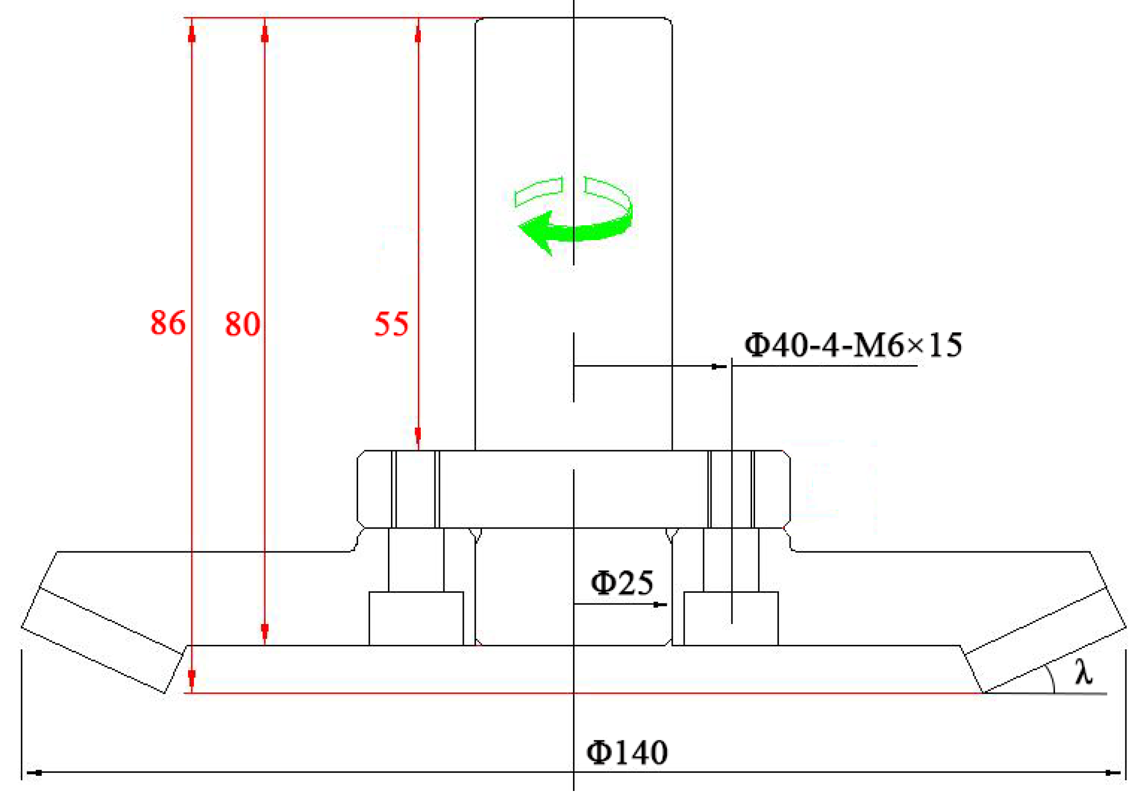
In this work, up-milling was carried out, which was performed in a machining center (MGK01, Nanxing Machinery Co., Ltd., Guangzhou, China) at a constant feed rate of 15 m/min. Glass MGO board was adopted as the machining object, and its mechanical properties are listed in Table 1. The polycrystalline cemented diamond (PCD) cutters used were made from diamond micro-powder sintered with a metal binder, and their main chemical components were carbon, cobalt, and tungsten carbide. As shown in Figure 1 and Table 2, all PCD cutters had the same material properties: a constant tool radius of 140 mm and a constant tooth number of six, but different taper angles, λ.
Orthogonal experimental design was used in this work, which is a design method of multiple factors at multiple levels [20] that can be used to study the influence of various factors (Table 3) on cutting force and cutting quality based on the orthogonal Latin squares table L9 (34) [21]. The specific experimental design is shown in Table 4. During each combination of cutting parameters, the cutting force and cutting quality were acquired and averaged from three measurements.
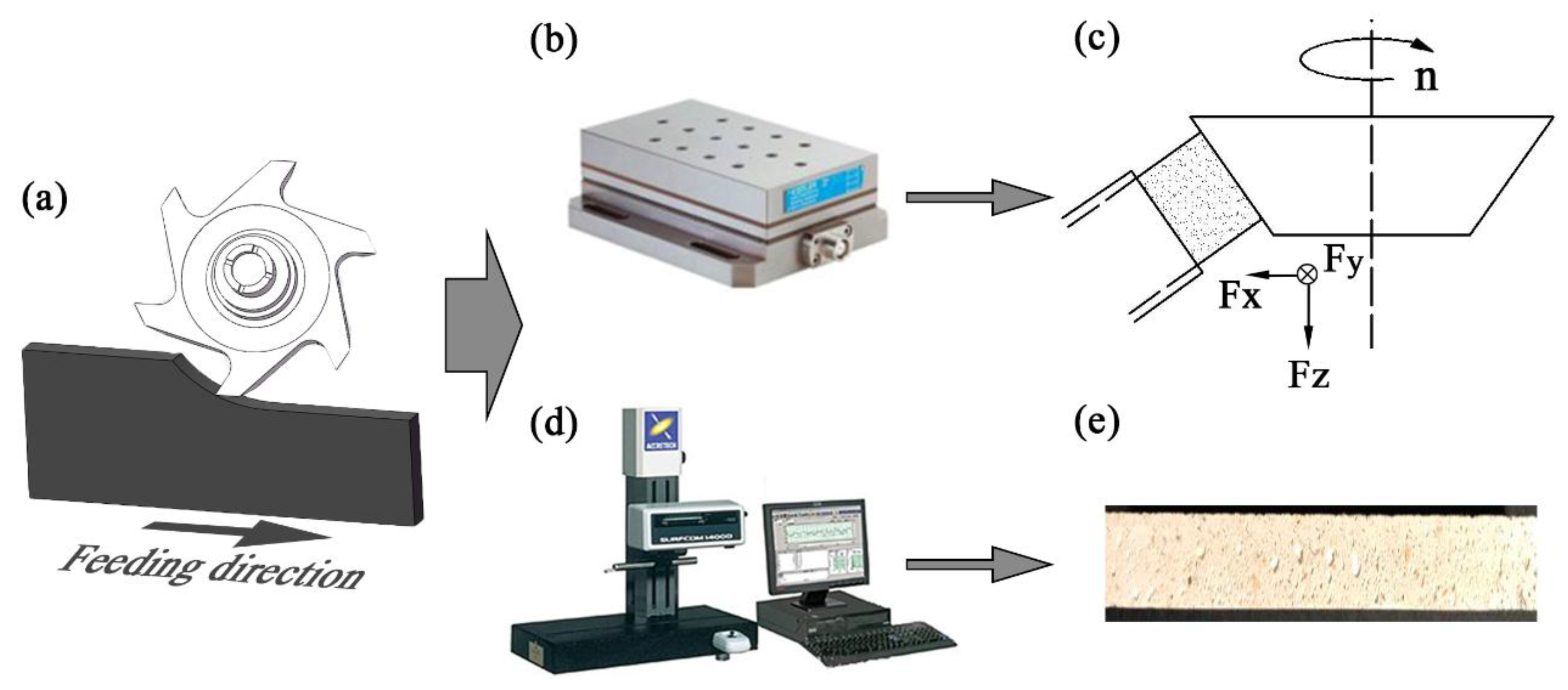
As shown in Figure 2a–c, the cutting force was measured by use of a Kistler three-component dynamometer and then calculated by using Dynoware specialized data processing software, where Fx is defined as the component force perpendicular to the feeding direction, Fy is the component force parallel to the feeding direction, and Fz stands for the component force parallel to the tool axis. In order to more intuitively investigate how various factors affect cutting force, resultant force, FR was used as an evaluation index of force, and obtained by Equation (1).
F R = F x 2 + F y 2 + F z 2
Surface roughness, Ra, was adopted to evaluate the cutting quality of the finished surface. Ra was measured by the surface profiler, and calculated by ACCTee software (Figure 2a,d,e).

3. Results and Discussion

3.1. Research on Cutting Force Based on Range Analysis

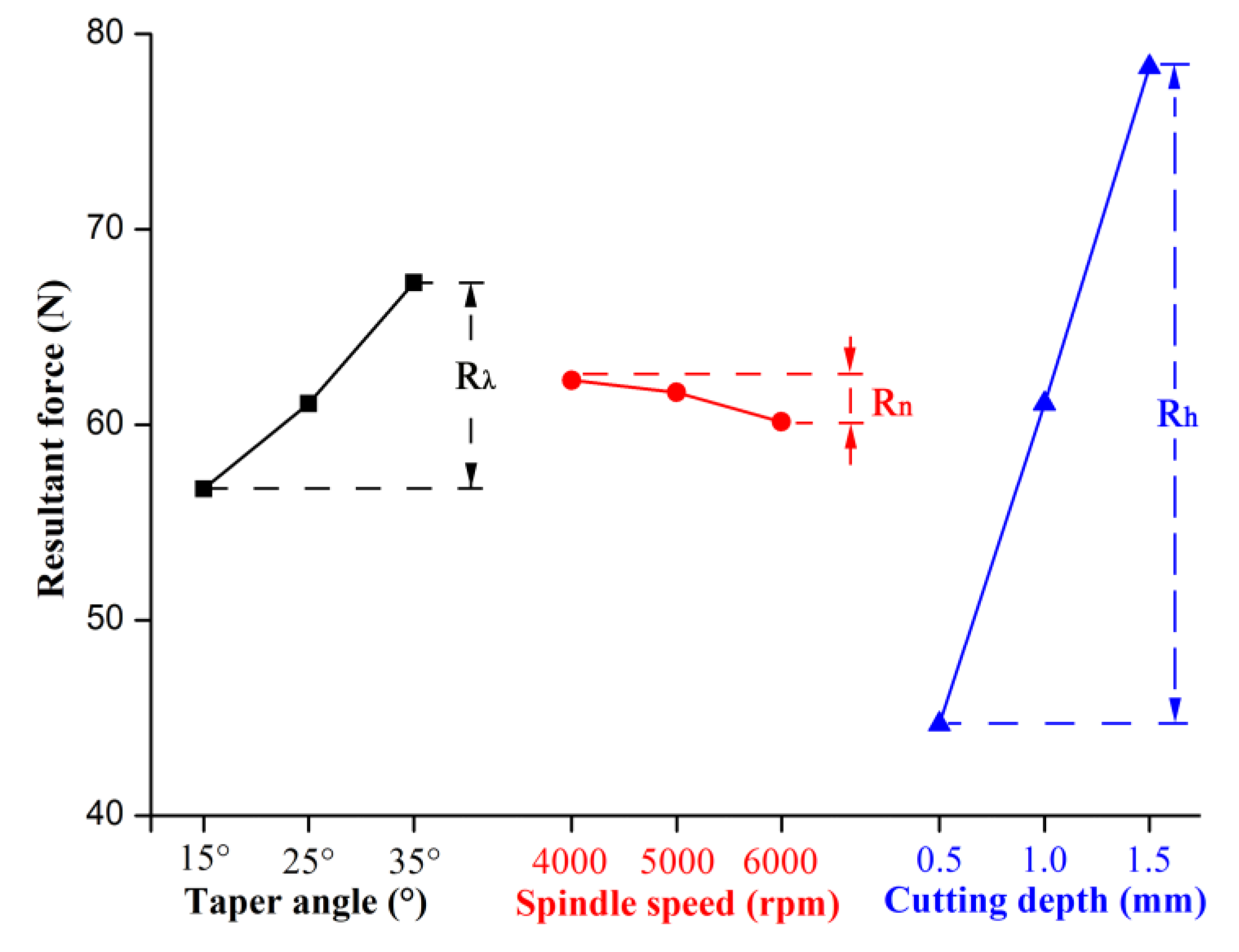
Table 4 shows the results of the resultant force via range analysis. The larger R values indicate a greater contribution of the factor on the results [20,21]. In this work, the solution shows Rh = 33.637 > Rλ = 11.563 > Rn = 2.123. Therefore, factor h (cutting depth) had the greatest influence on the cutting force, followed by factor λ (taper angle), and the factor n (spindle speed) had the least influence on the cutting force. In addition, taking the cutting force as the evaluation index, according to the value of Ki, the optimal combination of the three factors with the lowest cutting force could be selected. It can be concluded that the combination λ1n3h1 was the optimal cutting parameter, in which the taper angle was 15°, the spindle speed was 6000 rpm (43.96 m/s cutting speed, Equation (2)), and the cutting depth was 0.5 mm.
The effects of the taper angle and cutting parameters on the cutting force are displayed in Figure 3. It was found that the cutting force was enhanced with the increase of the taper angle, decreased slightly with the increase of the spindle speed, and increased with the increase of the cutting depth.
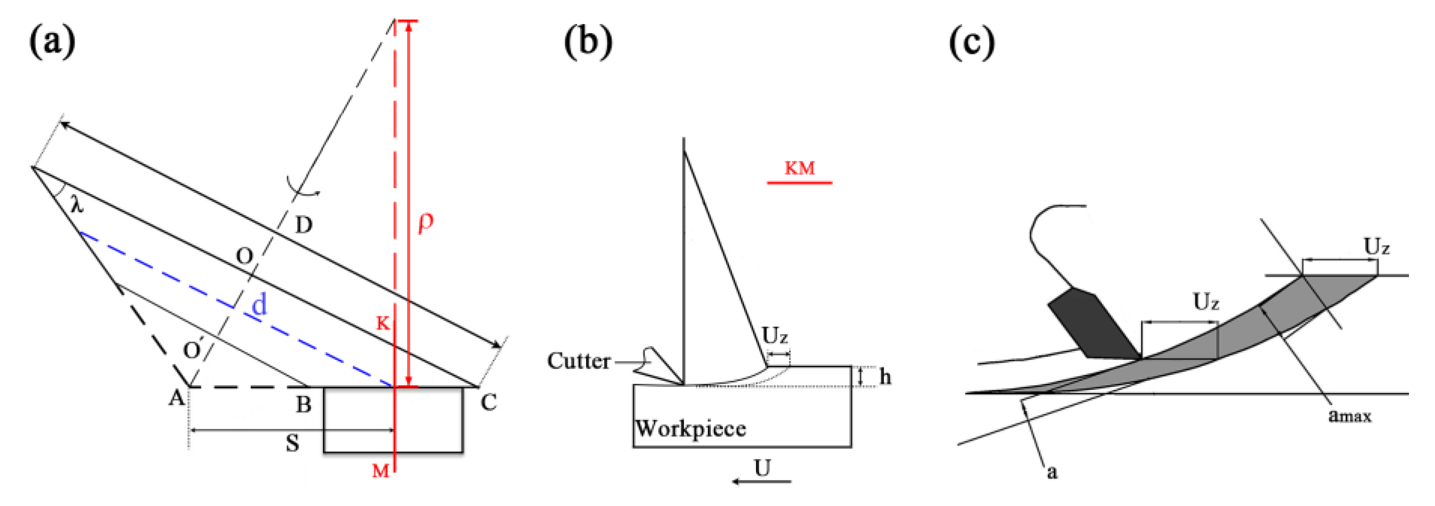
During the tapered milling, shown in Figure 4a,b, the cutting edge BC was rotated around the OO’ axis to form a tapered surface. By cutting the tapered surface with a plane (KM) perpendicular to the machined surface, the gyration radius, diameter of a point on the cutting edge, and cutting speed can be expressed as Equations (2)–(4), respectively.
ρ = S tan ( 90 ° λ )
d = S cos λ
V c = π d n 6 × 10 4
where ρ (mm) is the cutting radius of gyration at any point on the cutting edge BC, S (mm) is defined as the distance from the apex of the cone to the intercepted point, λ (°) is the taper angle, d (mm) is the diameter of a point on the cutting edge BC, and Vc (m/s) is the cutting speed of a point on the cutting edge BC.
An illustrative sketch of feed per tooth and chip thickness is displayed in Figure 4c. During cutting, the unwanted material above the cutting layer was removed by the rake angle and formed into chips. The chip volume, namely, removal quantity, was directly determined by feed per tooth and cutting thickness, as expressed by Equations (5) and (6) [15].
U Z = 1000 U n z
where Uz (mm) is the feed per tooth, U is the feed rate with a constant of 15 m/min, n (rpm) is the spindle speed, and z is the number of teeth, which was a constant of six in this work.
a a v = 1 2 a m a x = U z h D
where aav (mm) is the average cutting thickness, amax (mm) is the maximum cutting thickness, h (mm) is the cutting depth, and D is the tool radius with a constant of 140 mm.
According to above analysis, the increased taper angle led to a decreased gyration radius and increased cutting speed. The glass MGO board used was an inhomogeneous composite material, having many hard particles. When the cutting edge with a higher speed bit into the glass MGO board, the greater impact force would act on the cutter from the hard particles. Therefore, the cutting force showed a growing trend with the increase of the taper angle of the cutters. Meanwhile, the feed per tooth and average cutting thickness increased with decreasing the spindle speed and increasing the cutting depth. Thus, the cutting quantity per time during milling decreased with the increase of spindle speed, and increased with increasing cutting depth. A larger cutting quantity, indicating higher resistance, was generated during the machining process; therefore, the cutting force decreased with an increase in spindle speed, but increased with an increased cutting depth.

3.2. Research on Cutting Force Based on ANOVA (Analysis of Variance)

ANOVA and F tests were carried out to prove the significance of each factor. As listed in Table 5, the ANOVA analysis was adopted for a significance level of α = 0.05, namely, 95% confidence level. By comparing the F value of each factor with F0.05 = 19.00, if the F value of a factor was higher than the value of F0.05, namely, 19.00, the contribution of that factor was significant, otherwise it was insignificant [20,21]. In this work, the contributions of the taper angle (F0.05 = 19.00 < Fλ = 60.726) and cutting depth (F0.05 = 19.00 < Fh = 513.136) to the cutting force were significant, while the contribution of the spindle speed was insignificant (Fn = 2.162 < F0.05 = 19.00).

3.3. Range Analysis of Surface Roughness

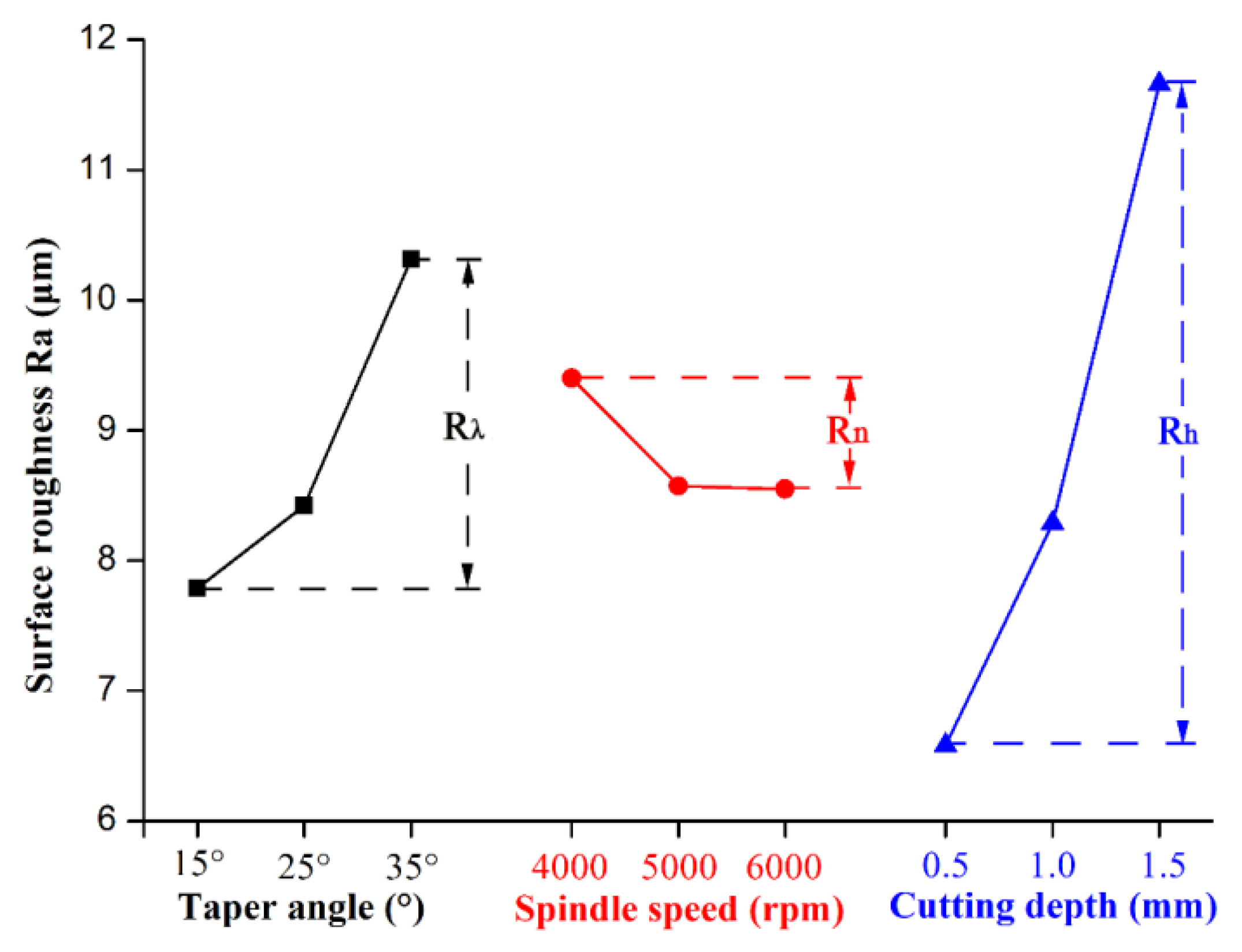
Results of the range analysis of the surface roughness are presented in Table 6. By comparing the R value of each factor, it was found that the Rh value was the largest, and the value of Rn was the smallest (Rh = 5.080 > Rλ = 2.527 > Rn = 0.853). Thus, this result indicates that the cutting depth had the greatest influence on the surface roughness, followed by the taper angle and the spindle speed. Meanwhile, taking the surface roughness as the evaluation index, according to the value of Ki, the optimal combination of the three factors with the lowest value of surface roughness could be selected. Hence, the combination of λ1n3h1 was adopted as the optimal cutting parameter, in which the taper angle was 15°, spindle speed was 6000 rpm (43.96 m/s cutting speed), and the cutting depth was 0.5 mm.
Figure 5 shows the influence of the cutting parameters on the surface roughness, which indicates that the surface roughness increased as the taper angle increased. According to Equation (2) and Figure 4a,b, with increasing the taper angle, the radius of gyration became smaller. The chip could not easily be removed from the workpiece by the cutter. Therefore, the surface roughness increased with an increasing taper angle. Similar to the results of Guo et al. [6] and Zhu et al. [22], the surface roughness decreased with the increase of spindle speed and increased with an increased cutting depth (Figure 5). As expressed in Equations (5) and (6), the increasing spindle speed and decreasing cutting depth reduced the feed per tooth and the cutting thickness during the milling process, directly lowering the resistance acting on the cutter and improving the cutting stability. Thus, the cutting quality was improved by increasing the spindle speed and decreasing the cutting depth.

3.4. Research on Surface Roughness Based on ANOVA

Table 7 lists the ANOVA results of the surface roughness in terms of a significance level of α = 0.05, namely a 95% confidence level. Based on judging the F value of each factor with F0.05 = 19.00, it was found that the contributions of the taper angle (Fλ = 9.941 < F0.05 = 19.00) and spindle speed (Fn = 1.358 < F0.05 = 19.00) to the surface roughness were insignificant, while only the cutting depth (F0.05 = 19.00 < Fh = 38.408) had a significant effect on the surface roughness.

3.5. Optimization and Verification

According to the range analysis and the ANOVA of the cutting force and surface roughness (Table 4, Table 5, Table 6 and Table 7), the optimum cutting combination was λ1n3h1, and cutting speed had an insignificant contribution to both the cutting force and surface roughness. In this case, considering the economic benefit, the spindle speed should be lower but still within an appropriate range, because a lower spindle speed reduces the energy consumption of the machine and causes more severe tool wear. Therefore, the optimal cutting parameters are assumed to be λ1n2h1, in which the taper angle is 15°, the spindle speed is 5000 rpm (36.63 m/s cutting speed), and the cutting depth is 0.5 mm. However, this combination of parameters was not previously performed in the orthogonal test. In order to verify the feasibility of this combination, a verification test was carried out and then compared with a control group, where the lowest cutting force and surface roughness were measured by orthogonal testing.
As shown in Table 8, when the taper angle was 15°, the spindle speed was 5000 rpm (36.63 m/s cutting speed), and the cutting depth was 0.5 mm, the cutting force and surface roughness were 36.67 N and 5.94 μm, respectively, which are all slightly less than the results of 39.43 N and 6.00 μm acquired by the combination of λ1n 1h1. In other words, the optimal cutting parameters assumed are matched and valid. Therefore, during the tapered milling of glass GMO board, the optimum cutting condition is 15° taper angle, 5000 rpm spindle speed (36.63 m/s cutting speed), and 0.5 mm cutting depth, which is proposed for actual machining in order to achieve a smoother machined surface and greater economic benefit.
4. Conclusions

In this work, tapered milling was conducted to machine glass MGO board via an orthogonal test design. The results show that the cutting force and surface roughness increase with the increase of the taper angle, and decrease slightly with increasing spindle speed, and furthermore are enhanced with increased cutting depth. Therefore, the cutting depth has the largest influence on the cutting force and surface roughness, followed by the taper angle and spindle speed. According to the ANOVA, the taper angle has a significant influence on the cutting force, but not on the surface roughness, while the spindle speed has an insignificant effect on both the cutting force and surface roughness. The contribution of the cutting depth to both the cutting force and surface roughness is significant. Finally, based on experimental optimization, the optimal cutting conditions were found to be 15° taper angle, 5000 rpm spindle speed (36.63 m/s cutting speed), and 0.5 mm cutting depth, which are proposed for the actual machining of glass MGO board to improve the quality of the machined surface and for economic benefit.

Author Contributions

Conceptualization, P.C.; methodology, Z.Z., C.F., C.Z.; software, X.G.; validation, P.C., X.G. and Z.Z.; formal analysis, X.W.; investigation, Z.Z. and X.W; resources, P.C. and X.G.; data curation, Z.Z.; writing—original draft preparation, P.C.; writing—review and editing, X.W.; visualization, Z.Z.; supervision, P.C.; project administration, X.G.; funding acquisition, X.G.

Funding

This research was funded by the National Natural Science Foundation of China, grant number 31500480, and the Doctorate Fellowship Foundation of Nanjing Forestry University.

Acknowledgments

The authors are grateful to Leuco Precision Tooling Co. Ltd. for supplying the diamond cutting tools used in this work.

Conflicts of Interest

The authors declare no conflict of interest.

References

  1. Manalo, A. Structural Behaviour of A Prefabricated Composite Wall System Made From Rigid Polyurethane Foam and Magnesium Oxide Board. Constr. Build. Mater. 2013, 41, 642–653. [Google Scholar] [CrossRef]
  2. Cao, Y.M.; Huang, L.Z.; Li, T.X.; Wang, X. Application of Modifier in Glass Fiber Magnesite Board. New Build. Mater. 2003, 8, 9–12. [Google Scholar] [CrossRef]
  3. Wang, Q.; Zhao, C.J.; Chen, G.Y.; Li, Y.; Wang, Y. Glass-Magnesium Composite Insulation Grid Roof Slab. New Build. Mater. 2005, 10, 25–27. [Google Scholar] [CrossRef]
  4. Park, J.W.; Huo, C.L.; Lee, S. Composition, Microstructure, Hardness, and Wear Properties of High-Speed Steel Rolls. Metall. Mater. Trans. A 1999, 30, 399–409. [Google Scholar] [CrossRef]
  5. Ramasamy, G.; Ratnasingam, J. A Review of Cemented Tungsten Carbide Tool Wear during Wood Cutting Processes. J. Appl. Sci. 2010, 10, 2799–2804. [Google Scholar] [CrossRef] [Green Version]
  6. Guo, X.L.; Zhu, Z.L.; Ekevad, M.; Xu, B.; Cao, P.X. The Cutting Performance of Al2O3 and Si3N4 Ceramic Cutting Tools in the Milling Plywood. Adv. Appl. Ceram. 2017, 117, 16–22. [Google Scholar] [CrossRef]
  7. Przestacki, D.; Jankowiak, M. Surface Roughness Analysis after Laser Assisted Machining of Hard to Cut Materials. J. Phys. Conf. Ser. 2014, 483, 012019. [Google Scholar] [CrossRef]
  8. Cao, P.X.; Zhu, Z.L.; Buck, D.; Guo, X.L.; Wang, X.D. Effect of Rake Angle on Cutting Performance during Machining of Stone-Plastic Composite Material with Polycrystalline Diamond Cutters. J. Mech. Sci. Technol. 2019, 33, 351–356. [Google Scholar] [CrossRef]
  9. Bolatashvili, N.D.; Mgaloblishvili, K.D.; Dadunashvili, G.G. Theoretical and Experimental Study of the Wear Factor for a Diamond Stone-Cutting Tool. Meas. Tech. 2009, 52, 292–295. [Google Scholar] [CrossRef]
  10. Uddin, M.S.; Seah, K.H.W.; Rahman, M.; Li, X.P.; Liu, K. Performance of Single Crystal Diamond Tools in Ductile Mode Cutting of Silicon. J. Mater. Process. Technol. 2007, 185, 24–30. [Google Scholar] [CrossRef]
  11. Pramanik, A.; Soon, N.; Rahman, M.; Li, X.; Sawa, M.; Meada, Y. Cutting Performance of Diamond Tools during Ultra–Precision Turning of Electroless Nickel Plated Die Materials. J. Mater. Process. Technol. 2003, 140, 308–313. [Google Scholar] [CrossRef]
  12. Reddy, S.K.; Rao, V. Experimental Investigation to Study The Effect of Solid Lubricants on Cutting Forces and Surface Quality in End Milling. Int. J. Mach. Tool. Manuf. 2006, 46, 189–198. [Google Scholar] [CrossRef]
  13. Li, W.; Zhang, Z.; Peng, X.; Li, B. The Influences of Circular Saws with Sawteeth of Mic-Zero-Degree Radial Clearance Angles on Surface Roughness in Wood Rip Sawing. Ann. For. Sci. 2017, 74, 37. [Google Scholar] [CrossRef]
  14. Li, R.R.; Xu, W.; Wang, X.D.; Wang, C.G. Modeling and Predicting of the Color Changes of Wood Surface during CO2 Laser Modification. J. Clean. Prod. 2018, 183, 818–823. [Google Scholar] [CrossRef]
  15. Zhu, Z.L.; Guo, X.L.; Ekevad, M.; Cao, P.X.; Na, B.; Zhu, N.F. The Effects of Cutting Parameters and Tool Geometry on Cutting Forces and Tool Wear in Milling High-Density Fiberboard with Ceramic Cutting Tools. Int. J. Adv. Manuf. Technol. 2017, 91, 4033–4041. [Google Scholar] [CrossRef]
  16. Fountas, N.A.; Ntziantzias, I.; Kechagias, J.; Aggelos, K.; João, P.D.; Nikolaos, M.V. Prediction of Cutting Forces during Turning PA66 GF-30 Glass Fiber Reinforced Polyamide by Soft Computing Techniques. Mater. Sci. Forum. 2013, 766, 37–58. [Google Scholar] [CrossRef]
  17. Gunay, M.; Seker, U.; Sur, G. Design and Construction of a Dynamometer to Evaluate the Influence of Cutting Tool Rake Angle on Cutting Forces. Mater. Des. 2006, 27, 1097–1101. [Google Scholar] [CrossRef]
  18. Fu, X.L.; Pan, Y.Z.; Yi, W.; Ai, X. Research on Predictive Model Surface Roughness in High Speed Milling for Aluminum Alloy 7050-T7451. Int. Conf. Comput. IEEE. Comput. Soc. 2010, 2, 186–189. [Google Scholar] [CrossRef]
  19. Sung, A.N.; Ratnam, M.M.; Loh, W.P. Effect of Wedge Angle on Surface Roughness in Finish Turning: Analytical and Experimental Study. Int. J. Adv. Manuf. Technol. 2014, 74, 139–150. [Google Scholar] [CrossRef]
  20. Colbourn, C.J.; Dinitz, J.H. Mutually Orthogonal Latin Squares: A Brief Survey of Constructions. J. Stat. Plan. Inference 2001, 95, 9–48. [Google Scholar] [CrossRef]
  21. Dukes, P.J.; Ling, A.C.H. A Three-Factor Product Construction for Mutually Orthogonal Latin Squares. J. Comb. Des. 2015, 23, 229–232. [Google Scholar] [CrossRef]
  22. Zhu, Z.L.; Buck, D.; Guo, X.L.; Cao, P.X.; Ekevad, M. Machinability of Stone-Plastic Materials during Diamond Planing. Appl. Sci.-Basel 2019, 9, 1373. [Google Scholar] [CrossRef]
Figure 1. Tapered cutter used in this work (mm).
Applsci 09 02533 g001
Figure 2. Schematic diagram of the cutting experiment: (a) tapered cutting, (b) dynamometer, (c) cutting force diagram, (d) surface profiler, (e) machined surface.
Applsci 09 02533 g002
Figure 3. Trends of cutting force under different cutting conditions.
Applsci 09 02533 g003
Figure 4. Motion analysis of the tapered milling: (a) taper milling, (b) cross-section KM of taper milling, (c) feed per tooth and chip thickness.
Applsci 09 02533 g004
Figure 5. Cutting parameters and surface roughness trend chart.
Applsci 09 02533 g005
Table 1. Material properties of glass magnesium (MGO) board.
WorkpieceDensityRupture StrengthImpact StrengthThermal Conductivity
Glass MGO1.12 g/cm324 MPa4.8 KJ0.64 W/m·K
Table 2. Tool angle and properties of polycrystalline cemented diamond (PCD) cutters.
PCD CuttersTool GeometriesMaterial Properties
Taper AngleRake AngleClearance AngleModulus of ElasticityThermal ConductivityHardness
115°10°800 GPa560 W·m−1·K−18000 HV
225°10°
335°10°
Table 3. Cutting parameters.
Levels Factors
Taper Angle (λ)Spindle Speed (n)Cutting Depth (h)
115°4000 rpm0.5 mm
225°5000 rpm1.0 mm
335°6000 rpm1.5 mm
Table 4. Range analysis of resultant force (FR).
Test NumberTaper Angle (λ)Spindle Speed (n)Cutting Depth (h)Resultant Force (FR)
115°4000 rpm0.5 mm39.43 N
215°5000 rpm1.0 mm55.41 N
315°6000 rpm1.5 mm72.31 N
425°4000 rpm1.0 mm62.60 N
525°5000 rpm1.5 mm77.83 N
625°6000 rpm0.5 mm42.87 N
735°4000 rpm1.5 mm84.81 N
835°5000 rpm0.5 mm51.74 N
935°6000 rpm1.0 mm65.29 N
K155.71762.28044.680
K261.10061.66061.100
K367.28060.15778.317
R11.5632.12333.637
Ki in the table represents the average value of the No. (i) of level data of each factor, and R represents the difference between the maximum value and the minimum value of each factor Ki, namely, the range of Ki.
Table 5. ANOVA results of resultant force (FR).
FactorsSum of squaresDegrees of freedomFProminence
Taper angle (λ)200.883260.726Significant
Spindle speed (n)7.15322.162Insignificant
Cutting depth (h)1697.4552513.136Significant
Error3.312
Total1908.8018
Table 6. Range analysis of surface roughness (Ra).
Testing NumberTaper angle (λ)Spindle Speed (n)Cutting Depth (h)Surface Roughness (Ra)
115°4000 rpm0.5 mm6.00 μm
215°5000 rpm1.0 mm7.42 μm
315°6000 rpm1.5 mm9.95 μm
425°4000 rpm1. mm8.06 μm
525°5000 rpm1.5 mm10.88 μm
625°6000 rpm0.5 mm6.32 μm
735°4000 rpm1.5 mm14.15 μm
835°5000 rpm0.5 mm7.42 μm
935°6000 rpm1.0 mm9.38 μm
K17.7909.4036.580
K28.4208.5738.287
K310.3178.55011.660
R2.5270.8535.080
Table 7. Analysis result of surface roughness (Ra).
FactorsSum of squaresDegrees of freedomFProminence
Taper angle (λ)10.37829.941Insignificant
Spindle speed (n)1.41821.358Insignificant
Cutting depth (h)40.098238.408Significant
Error1.042
Total52.9348
Table 8. Verification testing for resultant force (FR) and surface roughness (Ra).
TestingTaper Angle (λ)Spindle Speed (n)Cutting Depth (h)Resultant Force (FR)Surface Roughness (Ra)
Control group15°40000.539.43 N6.00 μm
Verified group15°50000.536.67 N5.94 μm