Article

Improved Control of Forest Microgrids with Hybrid Complementary Energy Storage

School of Technology, Beijing Forestry University, Beijing 100083, China
*
Author to whom correspondence should be addressed.
Appl. Sci. 2019, 9(12), 2523; https://doi.org/10.3390/app9122523
Submission received: 6 June 2019 / Revised: 18 June 2019 / Accepted: 19 June 2019 / Published: 20 June 2019
(This article belongs to the Special Issue DC & Hybrid Micro-Grids)

Abstract

:

Featured Application

The improved control method using complementary energy storage units can enhance the transient stability and operation reliability of microgrids in forests, providing theoretical support for the construction of forest microgrids.

Abstract

In order to improve the power quality and the fault ride-through capability of islanded forest microgrids, a hybrid complementary energy storage control method is proposed. In this method, mode-based sectional coordinated control is adopted as the basic control scheme, whereas control of the hybrid energy storage, which includes the battery, the supercapacitor, and the wind turbine, utilizes the improved strategy. According to the characteristics of the energy storage units, adaptive control of batteries and supercapacitors are adopted to smooth the low-frequency power fluctuation in the long-term and to suppress the high-frequency component separately, in which predictive control of the converters is utilized to achieve rapid regulation. Furthermore, as a third energy storage unit, the wind power unit was investigated, utilizing the large rotating kinetic energy of the wind turbine to temporally suppress huge power disturbance and avoid load shedding. To verify the effectiveness of the proposed coordination control with hybrid complementary energy storage, simulations of the islanded DC microgrid in forest area were conducted in MATLAB/Simulink, with the results showing that, by utilizing the improved control method, the transient operation characteristics of the system were effectively enhanced.

1. Introduction

With the increasing efforts of forestry encouragement and protection policy, the forest area and corresponding stock volume in China have achieved double growth. The carbon sink capacity of the forest has been greatly enhanced, and its ecological barrier function is stable, with good momentum for growth [1]. However, the gradual expansion of forest area has presented a major challenge to the power supply and distribution systems in forest areas. Capacity expansion of forest power networks always covers large areas with long transmission lines, which leads to huge construction investment and high loss in the power line. In addition, the maintenance area of the forestry power grid is expanded, and the corresponding human, material, and financial resources invested in operation and maintenance are increased. Therefore, the management pressure of power companies has risen remarkably [2,3,4].
As a low-cost utilization method of renewable energy, the microgrid, which is based on renewable energy, has the advantages of small initial investment, reliable power supply, small transmission loss, and flexible operation. It is a useful supplement to the utility grid, and helps to promote sustainable development of energy [5]. The microgrid can not only operate in grid-connected mode, but also in islanded mode, which makes it suitable for niche applications such as power supplies in isolated forest locations [6]. By effectively utilizing the abundant wind energy, biomass energy, and other natural energy locally, clean and efficient power can be provided for the loads in forests, such as monitoring and alarm systems, wood processing machinery, or electrical equipment on watchtowers. Therefore, the problems of power construction, operation, and management in remote forest areas can be solved.
Being different from islanded microgrids constructed in environments such as islands, microgrids in forests have their own ecological particularity. A large amount of residue from forest clearing, logging, and wood processing cannot usually be cleaned up and transported in time, which is a hidden hazard that may trigger forest fires [7]. Scientists in the United Kingdom and Sweden have proposed using the surplus produced by cleaning and afforesting to generate economic benefits, so as to promote the restoration of the forest ecosystem. American scientists have also paid great attention to wood power generation, and invested plenty of money on related research [8,9]. Using forestry residues for power generation can not only dispose of forest waste nearby, saving transportation costs and avoiding fires, but can also provide natural and environmentally friendly energy support for power loads in remote forest areas.
The forest microgrid in this paper, which is composed of a biomass power generation unit, wind power unit, and energy storage units, adopts a DC bus to improve stability and reliability during operation. In addition, in a DC microgrid there are no such problems as frequency deviation, reactive current circulation, and power angle stability, which are normally encountered in AC systems. The distributed generators and energy storage units in islanded DC microgrids are connected to the DC bus through power electronic converters, with asynchronous motors providing rotational kinetic energy as a natural inertial support. Therefore, the forest microgrid is an intrinsic small inertial system. In the case of large power disturbance, a sudden change of DC voltage will pose a threat to the voltage-sensitive load, leading to load shedding. In addition, fast variation of DC voltage caused by random fluctuations of distributed energy will also affect the quality of the output power. Therefore, it is of practical significance to investigate advanced control schemes of DC microgrids, in order to improve the transient response and ensure its safe and stable operation.
Scholars have proposed various control schemes of energy storage devices to suppress the power fluctuations of microgrids [10,11,12,13,14,15,16,17,18,19]. In Reference [10], a synergistic operation between converters of battery energy storage and a photovoltaic generator to assist management of microgrids is presented and in Reference [11], current-controlled bidirectional DC/DC converters were applied to connect each lithium ion battery bank as well. Although the control methods of converters in the above literature can ensure the basic stability of corresponding systems, time delay is inevitable, in which traditional proportional integral adjustment or corresponding improved forms based on deviation of the controlled variables are utilized. An experimental investigation of an energy storage unit which incorporates electric energy storage in the form of hybrid capacitors and hydraulic energy storage in the form of pressure vessels in a photovoltaic powered seawater reverse osmosis desalination system was proposed by Karavas, whereas there was only innovation in the energy storage form [12]. In Reference [13], a wireless droop control method for distributed energy storage units in AC microgrids is presented, which employs the SoC-based droop control method locally to prolong the service life of the energy storage, and in Reference [14], the energy storage was scheduled to work in a grid supportive manner, with a grid adaptive power management strategy being formulated to generate current references for energy storage systems and microgrid-connected converters. Both methods emphasize different priorities on various control targets, with indifference to improving control speed to enhance transient stability, which is critical in islanded microgrids. In References [15,16,17], optimal controls for microgrids with hybrid energy storage system were carried out using model predictive control (MPC), which allowed maximization of the economic benefits of the microgrids, minimizing the degradation causes of storage systems, or fulfilling other, different system constraints. The focuses of these papers are economical schedules in the upper control level, having nothing to do with improvement of the response speed or the transient characteristics of microgrids. A hierarchical control of a hybrid energy storage system, composed of both centralized and distributed control, was proposed in [18], and a method consisting of a virtual resistance droop controller and a virtual capacitance droop controller for energy storages with complementary characteristics was proposed in [19]. Although more accurate current references for DC converters were generated, the control speed of converters did not improve, which weakened the effectiveness of the control strategy. In References [20,21], the authors used a two-level control scheme to control the charge/discharge power of the storage unit, in which the reference in the first level was obtained through a robust optimal power management system. Moreover, the research on inertial control of the energy storage system was limited to adding a supercapacitor into the microgrid to improve the equivalent inertia, whereas the effect of disturbance suppression was not obvious [22,23,24].
In this paper, a coordination control strategy of hybrid complementary energy storage in a forest microgrid is proposed, to improve its transient operation stability and the fault ride-through capability. The battery, the supercapacitor, and the wind turbine energy storage unit constitute the hybrid energy storage system, all of which undertake different tasks in maintaining power balance under various operation modes. To better ensure the control speed and efficiency of the battery and the supercapacitor under power fluctuation conditions, the adaptive droop coefficients and predictive converter control method are firstly proposed. In the following, an inertia enhancement control strategy of the wind turbine, utilizing its rotating kinetic energy, was investigated to improve its fault ride-through capacity in urgent conditions, such as load shedding. In addition, overall control of the hybrid complementary energy storage system was studied based on the fundamental DC voltage sectional control to coordinate various energy storage units.
This paper is organized as follows. Section 2 presents the basic operation mode and coordination control of DC microgrid. Section 3 describes the hybrid complementary energy storage system, while the overall control of the forest microgrid is discussed in Section 4. Simulations are presented in Section 5.

2. Operation Mode and Coordination Control of Microgrid in Forest Area

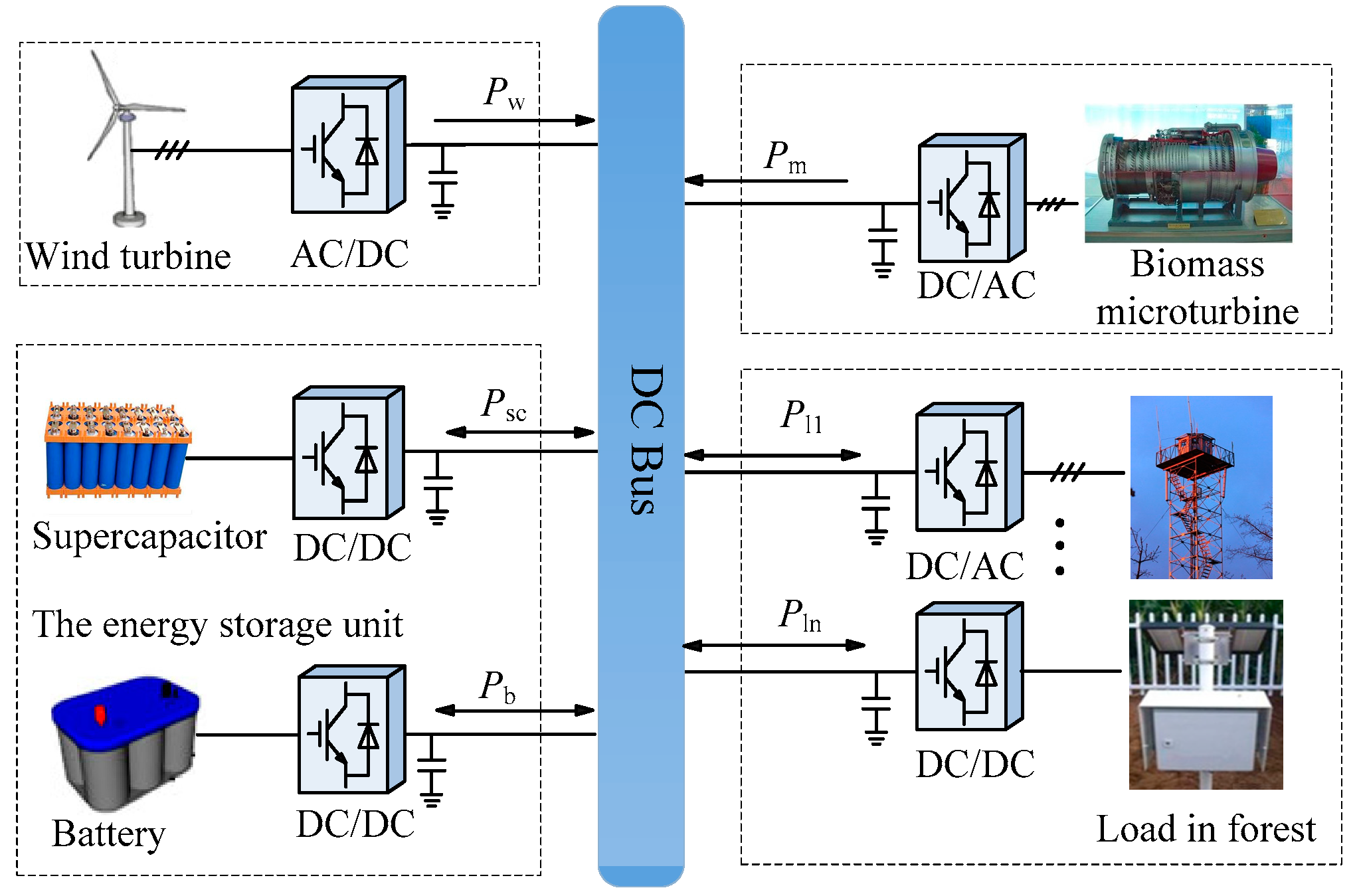
2.1. Structure of the Forest Microgrid

The forest microgrid adopts a DC bus due to the advantages of flexible control, low line loss, and high conversion efficiency, which determine it to be a more ideal connection pattern than its AC counterpart. Therefore, it is conducive to the flexible access of renewable energy and the realization of intelligent power supply in remote forest areas.
In this paper, the forest microgrid, which is composed of the biomass power unit, the wind power unit, and energy storage units, adopts multiple energy sources in complementary forms. As the microgrid is designed for remote forest areas, which are hard to access by the utility grid, it operates in islanded (off-grid) mode. Moreover, radiation topology is adopted by the system with simple structure and low construction cost, as is shown in Figure 1.
When the system operates normally, the wind power unit provides green energy to support the microgrid. The biomass power generation unit generally operates in hot standby mode, while the supercapacitor, which cooperates with the biomass unit or batteries, is utilized to eliminate fast power disturbance of the system, based on its characteristic of fast charging and discharging. In addition, the battery energy storage system is an emergency power supply unit, which can realize bidirectional power flow through the DC/DC converter. According to the operation characteristics of each unit, the operation mode of the forest DC microgrid can be divided into the following four parts.

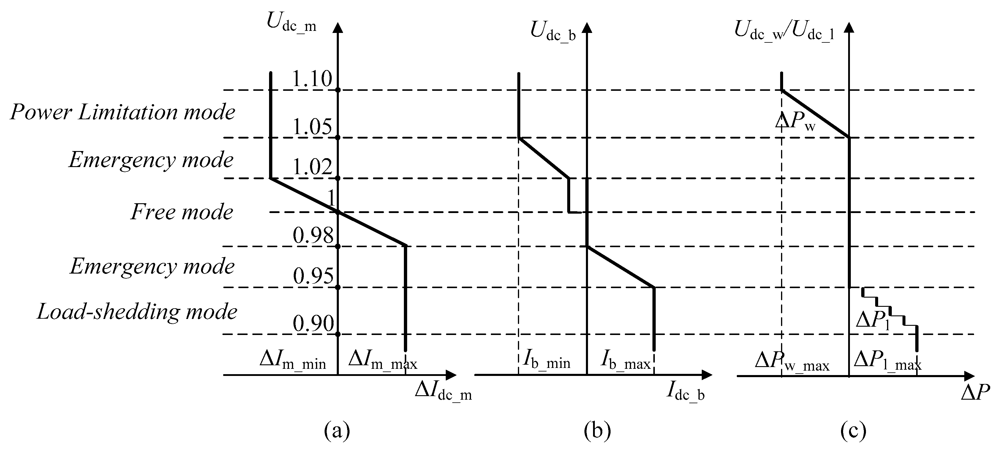
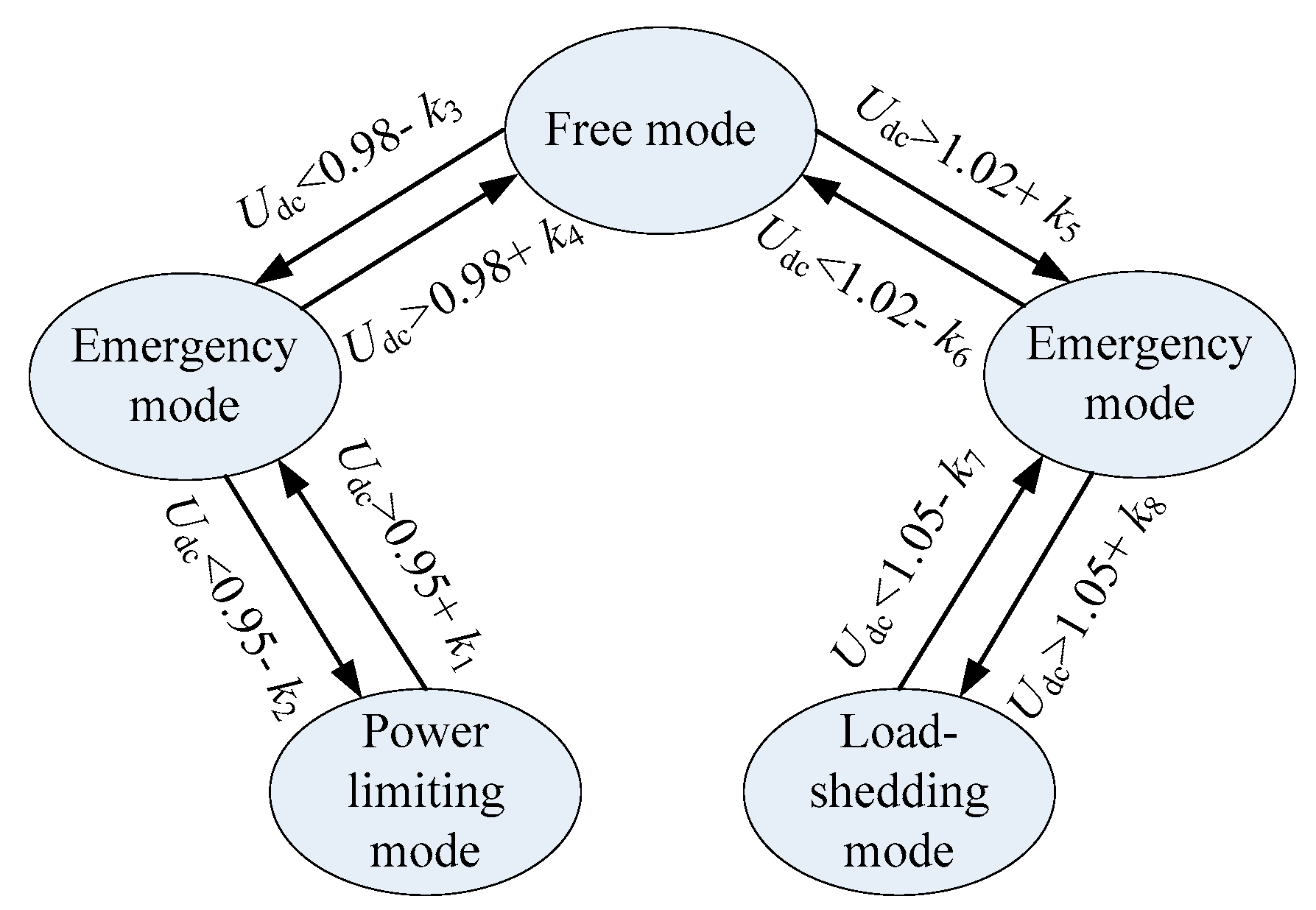
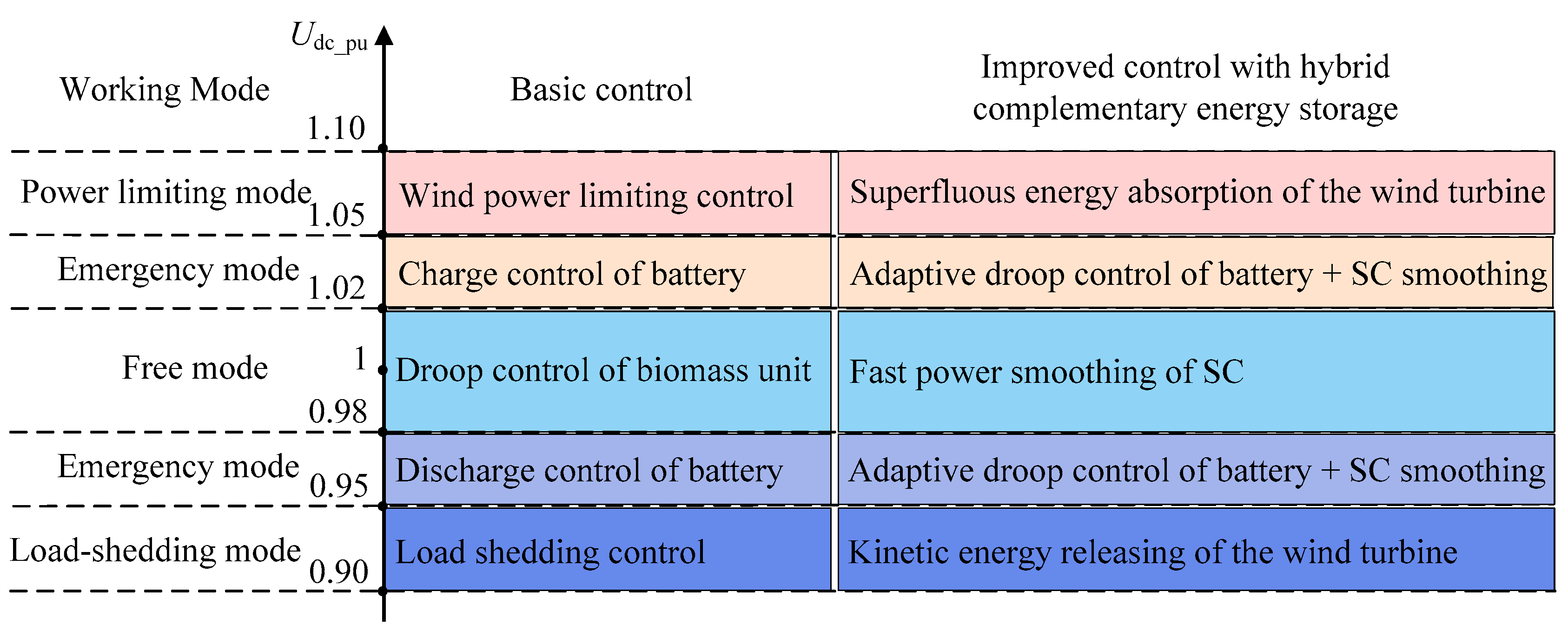
2.2. Operation Mode of the Forest Microgrid

2.2.1. Free Mode

Being different from a grid-connected microgrid, the forest microgrid is isolated from the utility grid and is an energy self-sufficient system. In free mode, the system operates normally under small power disturbance, with DC voltage of the microgrid being in the interval of [0.98, 1.02] pu (per-unit value). The wind turbine unit carries out maximum power point tracking, while the biomass power generation unit takes in charge of suppressing the power disturbance by regulating its output power. Furthermore, the supercapacitor performs high frequency power smoothing and the battery is charged with a small constant current when the voltage is above its rated value.

2.2.2. Emergency Mode

When the wind is relatively weak or the output of the biomass power generation unit is limited, the DC voltage of the microgrid will drop below 0.98 pu. Under these circumstances, the energy storage system discharges to supplement the power gap. When the output of the wind power generation system is so high that the DC voltage rises above 1.02 pu, the biomass power generation unit withdraws automatically. In this case, if the system power is still excessive, the battery can be charged only when its state of charge is below the upper limit.

2.2.3. Power Limiting Mode

When the wind power is greater than the aggregate demand of the load and the energy storage systems, maintaining maximum power point tracking of wind power unit will lead to a sharp rise in DC bus voltage to above 1.05 pu. Therefore, inertia control of the wind turbine will be conducted, which temporarily stores the excess power in the form of kinetic energy of the wind turbine. If the working condition continues, power-limiting control of the wind power unit should be carried out to maintain stability of the system.

2.2.4. Load-Shedding Mode

When the power deficiency lasts and the load demand is still unable to be met, even if the energy storage is depleted, the wind turbine releases its kinetic energy to temporarily extend the operation time of the load. Under long working conditions of low power input, the load needs to be shed according to priority.

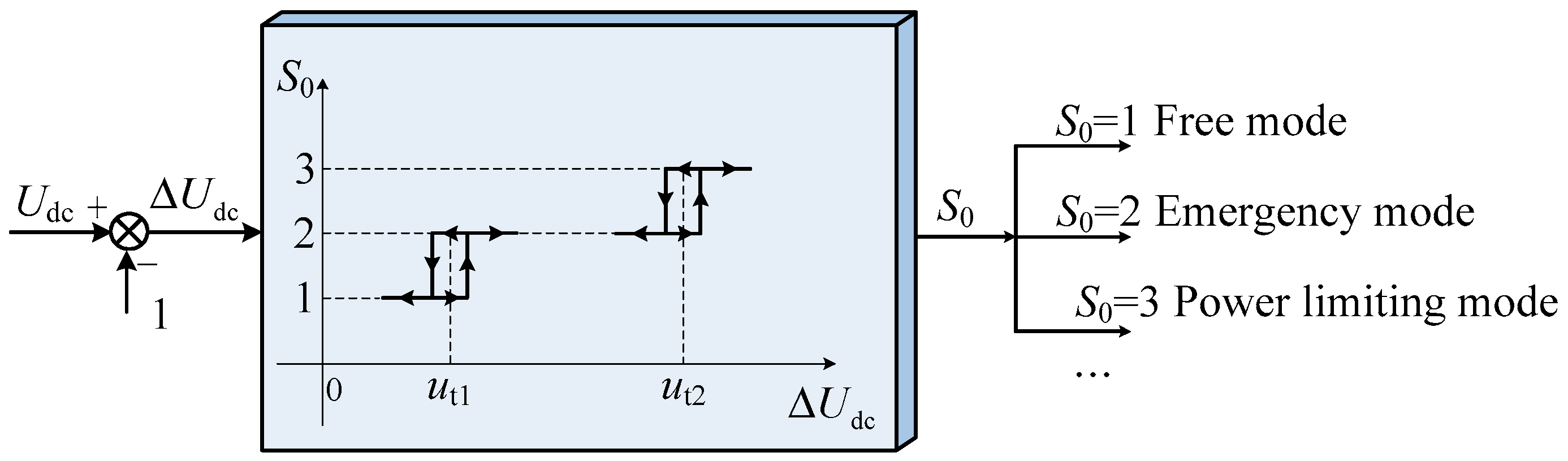
2.3. Coordination Control

With no frequency and reactive power in the DC microgrid, the DC voltage fluctuation is mainly caused by the uncertainty of system input power [25]. As the DC bus voltage reflects the internal power state of the microgrid and is a sign of system stability, power–voltage regulation is the core of stability control, as well as energy management. This paper utilizes DC bus voltage as the basis for operation mode, switching of each unit to effectively simplify system control.
In this method, the various units of the system are divided into a slack terminal, which is responsible for adjusting power, and power terminals, with constant output in different working modes, as is shown in Figure 2. They are not static, and switch with the change of the operating state of the system. The corresponding switching diagram of control mode is shown in Figure 3. For example, under free mode and emergency mode, the primary power regulating units of the system are the biomass power generation unit and the energy storage unit, respectively. In power limiting mode, the corresponding power control unit is the wind power system.
In addition, the supercapacitor functions under the condition of rapid power fluctuation in free mode and emergency mode, while kinetic energy regulation of the wind turbine acts under large power disturbances in power limiting mode as well as load shedding mode.
In the DC microgrid, as the voltage value at the DC bus of each unit makes very little difference, the working mode of each unit can be determined only by detecting the DC voltage at the outlet of each converter. Consequently, there is no need to establish a complex communication system by utilizing an operation mode-based sectional coordinated control strategy. With the characteristic of plug and play, the coordinated control method has the advantage of simplicity and reliability. In addition, it boasts the feature of self-adaption besides coordination of different units. Due to the fact that the operation mode of the system is divided based on DC voltage, and under each mode power regulation is conducted by the most suitable controllable unit, the stability of the islanded system can be ensured.

3. Hybrid Complementary Energy Storage System

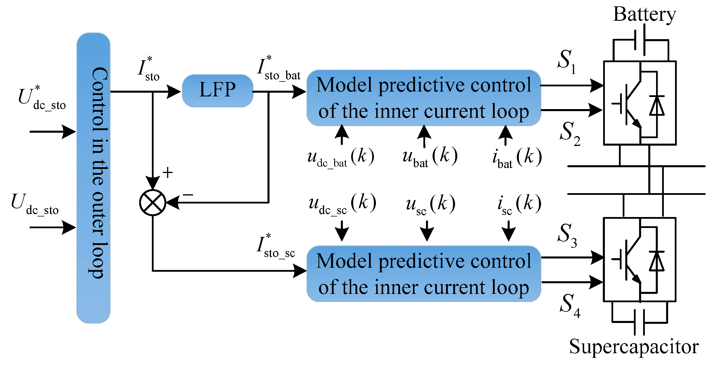
3.1. The Necessity of the Hybrid Complementary Energy Storage

The DC microgrid based on power electronic converters is a system with small inertia, which presents large fluctuation when being subjected to power disturbance. Although microgrids are normally equipped with an energy storage device to ensure stability of the system, when confronted with temporary high power fluctuations, the control system may fail to respond in time due to control delay. In this condition, load shedding or system protection will be caused. By coordinating the three kinds of energy storage units proposed in the DC forest area microgrid, adopting the appropriate energy storage unit to suppress system disturbances under different operation modes or disturbance conditions, the response characteristics of the system can be improved. Accordingly, as the transient stability of the system is enhanced, large fluctuations of DC voltage can be restrained.
As batteries have the advantage of high energy density, they are suitable for long term energy storage to compensate for power gaps when system input is limited in emergency mode. However, their charge–discharge efficiency is low, which is not recommended for frequent action to suppress power fluctuations. Contrarily, supercapacitors have the merits of high power density and long cycle life, as well as high charge and discharge efficiency [26]. Therefore, they are appropriate for suppressing the power fluctuations with high frequency and small amplitude that are typical in free mode and emergency mode, to assist the biomass unit in power regulation. In addition, by exploiting the large rotating kinetic energy of wind turbine, large disturbances of the system can be suppressed, which can effectively improve the fault ride-through capability of the microgrid and avoid load shedding.

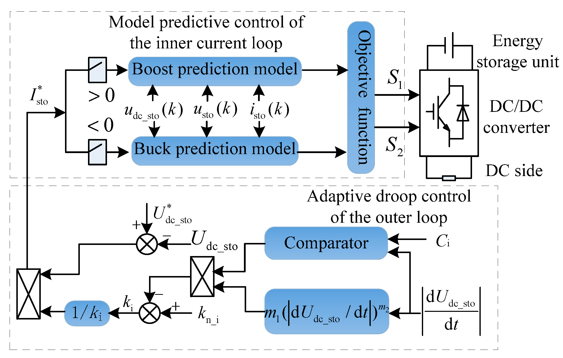
3.2. Improvement in Traditional Control of Batteries and Supercapacitors

The reference current absorbed or released by the energy storage system is divided into a low frequency part and a high frequency part through the low pass filter (LPF). As batteries boast high energy density and large energy storage, they are used as long-term devices for power balance by absorbing or releasing low frequency power, while supercapacitors are utilized for suppressing high frequency disturbances.
The power disturbances that lead the system to emergency mode always give rise to large change rates of DC voltage (dUdc/dt). Therefore, dUdc/dt can be utilized to adaptively modify the droop coefficient of the energy storage converter. When it exceeds the preset threshold C, the droop coefficient ki varies adaptively to improve the response speed, as shown in Equation (1).
k i = { k n _ i m 1 ( | d U dc d t | ) m 2 , for | d U dc d t | C k n _ i , for | d U dc d t | < C ,
where kn_i is the droop coefficient of the converter in the original control method. Constants m1 and m2 are based on the rated capacity of microgrid converter and the maximum allowable deviation of DC voltage. m1 is determined by the following Equations.
m 1 = k n _ i k i _ min ( | d U dc d t | max ) m 2 ,
k i _ min = Δ U dci Δ I i _ max ,
where ki_min is the minimum droop gain, the selection of which is to prevent the output power of the converter from exceeding its maximum limit. ΔUdci is the variation of DC voltage corresponding to the maximum current limit (ΔIi_max) of the convertor, and is intended for setting the allowable voltage variation corresponding to a specific converter.
The value of m1 depends on the output capacity of the converter represented by the maximum voltage change rate |dUdc/dt|max and ki_min. The power support capability of the energy storage converter increases in the same direction with m1. A small m1 may result in transient overshoot of DC voltage, while a large one may cause power oscillation of the system. Therefore, it is critical to select an appropriate m1. Similarly, a smaller m2 corresponds to smaller droop coefficient of the converter, which implies more power available at the instant of disturbance, providing reliable energy support for the system.
The generation procedure of the reference value of the energy storage converter with an adaptive droop coefficient is shown in Figure 4. When the system operates steadily, the change rate of DC voltage is less than the set threshold Ci. Therefore, the output of the comparator is 0, and the converter operates with the original droop coefficient. When the system is disturbed rapidly with large amplitudes, which leads the system to emergency mode, the change rate of DC voltage may exceed the set threshold. Under this circumstance, the output of the comparator is 1 and the dynamic droop coefficient of the converter is adopted, which smooths the DC voltage.

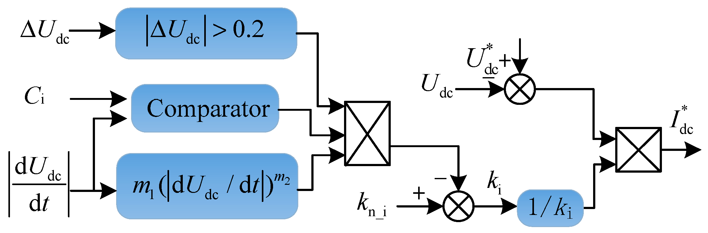
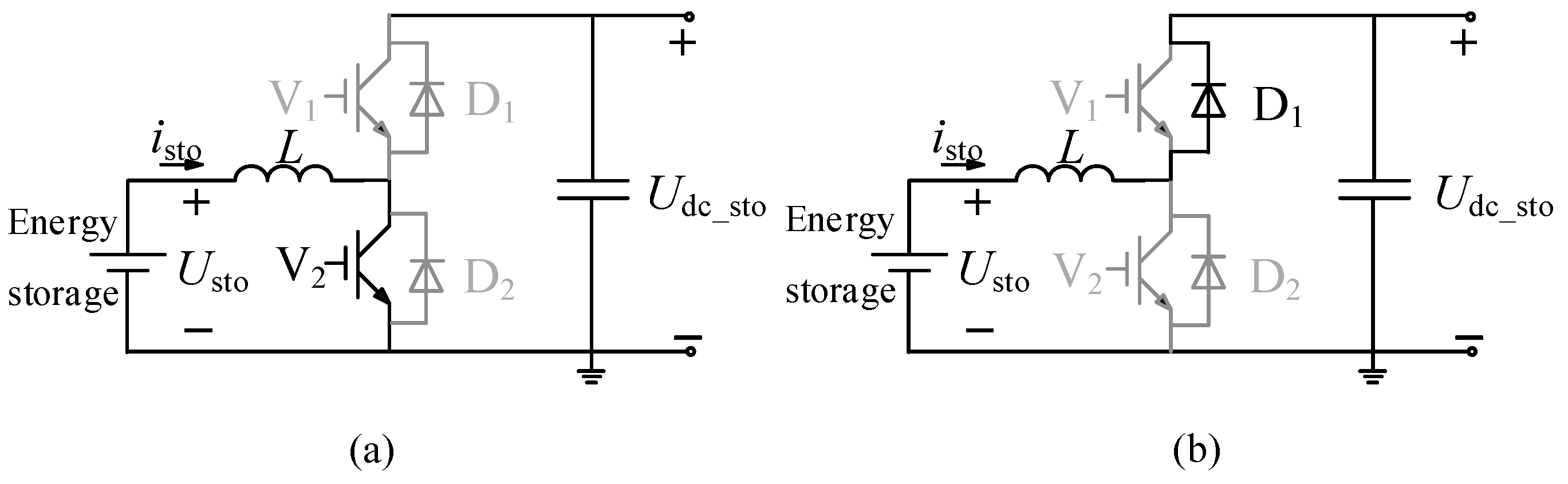
3.3. Predictive Converter Control Method

Achieving fast smoothing of the system power requires fast converter control, whereas adopting the routine method based on real time value of DC/DC converters may weaken the effect of the self-adaptive droop control due to the lag regulation of current. Therefore, a predictive control method is proposed for the hybrid energy storage system to improve corresponding regulation speed. The converters of the supercapacitor and battery adopt the same Buck/Boost topology, as shown in Figure 5, with the switches V1 and V2 operating complementarily [27]. When the DC voltage in the microgrid is lower than the switching threshold, the energy storage unit discharges, in which condition the converter works in Boost mode. Contrarily, when there is power surplus and the energy storage unit needs to be charged, the converter switches to Buck mode.
The converter of the energy storage system usually adopts a double closed-loop control structure, with the outer-loop being voltage control and the inner loop current control. Being different from the commonly used PI control method, the predictive control method based on converter model collects the current state variables of the system and calculates the predictive current value at the next moment through the predictive model. The switching action of the converter is then chosen by minimizing the deviation between the predicted current value and the reference one [28]. This method adopts active predictive control instead of passive feedback regulation, which effectively avoids the time lag in traditional PI-based current regulation within the inner loop. Therefore, the predictive method is suitable for the occasion of voltage regulation, which requires high control speed.

3.3.1. Current Prediction Model of Converter

In Boost mode, V2 and the anti-parallel freewheeling diode D1 are in working state. During the turn-on stage of switch V2 (Sc2 = 1), the energy storage unit charges the inductor L through V2, as shown in Figure 5a. Equation (4) can be obtained from its equivalent circuit, which is further discretized to obtain the predicted current value at the k + 1th moment, shown in Equation (5).
L d I sto / d t = U sto ,
i sto ( k + 1 ) = T s u sto ( k ) / L + i sto ( k ) ,
where usto(k) denotes the voltage detected at both ends of the energy storage unit (the battery or the supercapacitor) at the kth moment; isto(k) represents the current of the energy storage unit, which flowing through inductance L at the kth moment and Ts is the sampling period.
During the switching off stage of V2 (SC2 = 0), the electromagnetic energy stored in inductance L is released to the DC side through the anti-parallel freewheeling diode D1. The following formula can be obtained from the circuit shown in Figure 5b.
L d I sto / d t = U sto U dc _ sto .
Equation (6) is discretized and the predicted current is as follows.
i sto ( k + 1 ) = T s [ u sto ( k ) u dc _ sto ( k ) ] / L + i sto ( k ) ,
where udc_sto(k) denotes the DC side voltage of the converter at the kth moment.
Similarly, when the bidirectional DC/DC converter operates in Buck mode, its prediction model of current is established as follows.
{ i sto ( k + 1 ) = T s [ u sto ( k ) + u dc _ sto ( k ) ] / L + i sto ( k ) , ( S C 1 = 1 ) i sto ( k + 1 ) = T s u sto ( k ) / L + i sto ( k ) , ( S C 1 = 0 ) ,
where SC1 = 1 represents the conducting state of switch V1.

3.3.2. Objective Function of the Converter Predictive Control

In order to realize fast regulation of the inner loop current of the converter, predictive control should aim for fast tracking of the reference current generated from the outer loop, as shown in Equation (9).
J = | i sto ( k + 1 ) I sto * | .
On the basis of collecting the state information of the system at the current moment, the predicted values of the converter inductor current under different switching states can be calculated though the prediction model. The switch state with the smallest deviation between the predicted current and corresponding reference value is then selected as the system output to control the converter. As a result, fast current tracking can be achieved through active predictive control.
By combining the model predictive method of current inner loop with the adaptive droop control in the outer loop of the energy storage control system, fast power regulation of energy storage units under various working modes can be achieved, which stabilizes the DC voltage. The general control chart of the predictive method with adaptive droop control in the outer loop for different energy storage units is presented in Figure 6.
As mentioned before, the supercapacitor is appropriate for suppressing high frequency power fluctuations with small amplitude, which are hard for the biomass thermal unit or the battery to stabilize. On the contrary, the battery, which has large amount of stored energy and high energy density, is always utilized as a long-term power balance device to absorb or release power with low frequency. The reference current absorbed or released by the energy storage system is divided into two parts, namely, the low-frequency part and the high-frequency one, through the low pass filter LPF. The corresponding control block diagram of the hybrid energy storage system is shown in Figure 7.

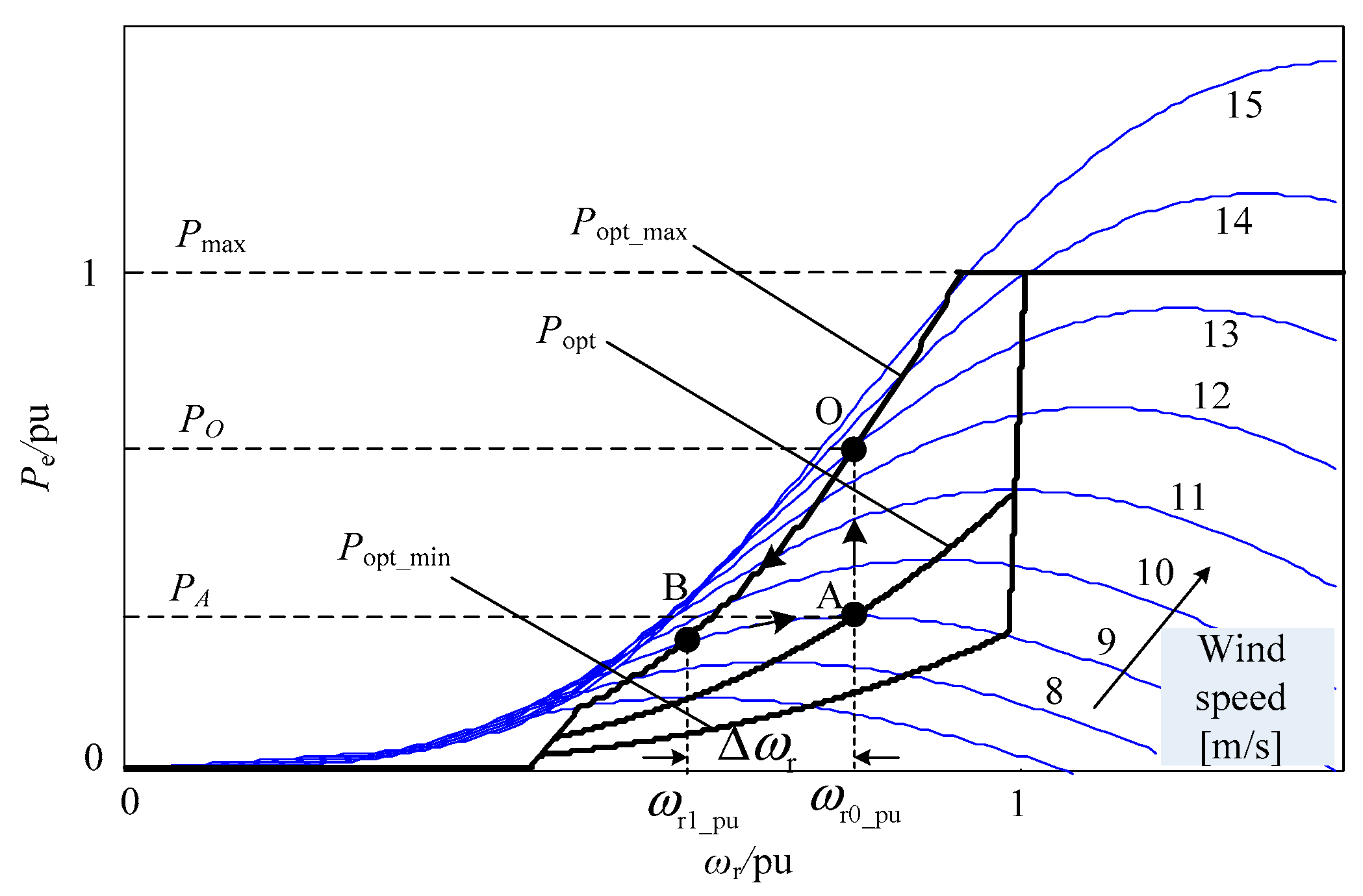
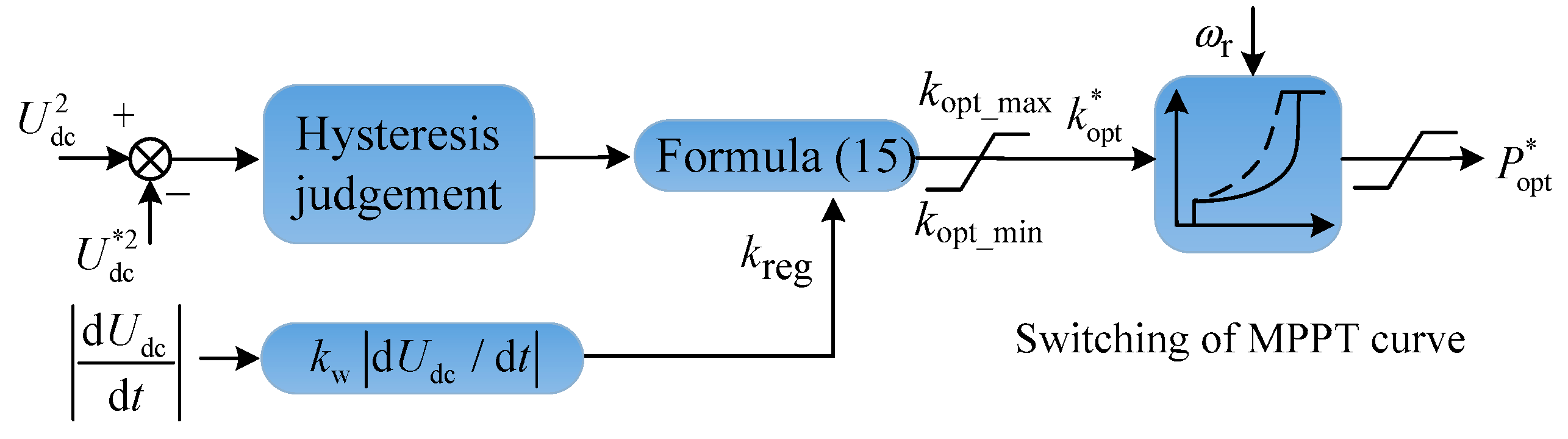
3.4. Control of the Energy Stored in the Wind Turbine

In the wind power generation system, the wind turbine can store or release rotational kinetic energy through the change of its rotational speed, which makes it “the third energy storage unit” in the microgrid. However, in a converter-based microgrid, the direct connection between the disturbance in DC side and the change of rotational kinetic energy in the wind power system is isolated by the turbine-side converter. Generally, the wind power unit operates in maximum power point tracking (MPPT) mode, in which the output electric power is independent of the change of DC voltage. Therefore, auxiliary control is needed to establish the correlation between the kinetic energy of the wind turbine and the DC voltage, so that the mechanical rotation system can provide power support for the microgrid under conditions of significant change in DC voltage, to enhance its capability of fault ride-through.
When disturbance of DC bus voltage occurs, the charge or discharge power of the DC side capacitor in parallel with the wind power converter is calculated as follows.
Δ P dc = C w U dc d U dc d t ,
where Cw is the DC side capacitor of the wind power system converter.
The variation of the output power caused by the change of the generator speed in the wind power unit is shown in Equation (11).
Δ P e = d E k d t = J ω r d ω r p 2 d t ,
where ΔPe is the power variation of the wind power unit, Ek is the rotating kinetic energy of the generator, J is the rotating inertia of the synchronous generator, ωr is the angular speed of the synchronous generator, and p is the number of pole pairs of the generator. As the wind turbine and the permanent magnet generator are directly coupled, the generator speed is equal to that of the wind turbine.
As the mechanical energy of the wind turbine is much larger than the energy stored in the capacitor, variation of the wind turbine speed is much smaller than that of the DC voltage when bearing the same amount of power disturbance. To quickly restrain the fluctuation of DC voltage with urgency, it is necessary to transform the power unbalance on the DC side into the change of rotational kinetic energy of the wind turbine through a control method. Therefore, fluctuation of DC bus voltage can be assumed by the wind turbine. The following equation is available by combining Equations (2) and (3).
J ω r d ω r p 2 d t = C w U dc d U dc d t .
The relationship between the variation of the wind turbine speed and the change of DC voltage under the same power disturbance is obtained by integrating and normalizing both sides of Equation (12) simultaneously. It is assumed that the voltage is kept at its rated value Udc_N before occurrence of the disturbance.
ω r 1 _ pu 2 ω r 0 _ pu 2 = 1 2 C w U dc _ N 2 1 2 p 2 J ω r _ N 2 ( U dc _ pu 2 1 ) = k r e g ( U dc _ pu 2 1 ) ,
where ωr0_pu and ωr1_pu are the per-unit values of the angular speed of the generator before and after disturbance, respectively; Udc_pu is the per-unit value of DC voltage after disturbance; ωr_N is the rated speed of the generator. kreg is defined as the speed regulation coefficient, and varying degrees of regulation of the DC voltage can be achieved by setting different values of kreg to ensure smooth transition of the microgrid during major disturbances.
Figure 8 is the switching principle of the improved MPPT curve with speed response of the wind turbine when disturbance occurs in the DC voltage of the microgrid. As shown in this figure, Popt is the maximum power point tracking curve, which determines the output of wind power unit under normal conditions. In addition, the curves Popt_max and Popt_min are the upper and lower limits of the output power, respectively. Usually, the microgrid is stable and the wind power unit operates at point A, with the proportional coefficient of MPPT curve being kopt0. When a steep fall of the DC voltage occurs due to a sudden power vacancy, a large amount of energy is needed to reduce the change rate of DC voltage so that load shedding can be avoided. At this time, the curve switches to Popt_max and the operating point moves from A to O, with the proportional coefficient rising to kopt_max. The wind turbine, which connects directly to the generator, slows down due to the fact that the output electromagnetic power is larger than the mechanical power captured by the wind turbine, and the operation point decreases to B along Popt_max. With the recovery of DC voltage, the proportional coefficient decreases gradually from kopt_max to kopt0, with the power tracking curve cutting back to Popt slowly and smoothly. Therefore, the wind turbine recovers and operates again at point A. Similarly, the switching process of the operation points can be analyzed when DC bus voltage surges.
Point A and point B in Figure 8 correspond to the rotational speed ωr0_pu and ωr1_pu, respectively. When the range of speed regulation is not wide, the output power of point A and point B is approximately equal, as shown in Equation (14).
k opt ω r 1 _ pu 3 = k opt 0 ω r 0 _ pu 3 ,
where kopt is the proportion coefficient of power tracking curve after adopting the improved speed control. kopt can be obtained by introducing Equation (13) into Equation (14).
k opt = ω r 0 _ pu 3 [ ω r 0 _ pu 2 + k reg ( U dc _ pu 2 1 ) ] 3 / 2 k opt 0 .
In order to adjust the inertia response of the wind power unit according to the change rate of DC voltage in microgrid, the speed regulation coefficient kreg is modified by the change rate signal to be kreg = kw |dUdc/dt|, where, kw is a constant. By utilizing the proportional coefficient kopt calculated in Equation (15) instead of the fixed proportional coefficient kopt0, adaptive speed response of the wind power system can be achieved to quickly adjust the output power by using the energy stored in wind turbines. The block diagram of the improved control strategy for the wind power system is shown in Figure 9, where kopt_min and kopt_max are the limit values of the proportional coefficient.

4. Overall Control of the Forest Microgrid

The basic control and the improved control with hybrid complementary energy storage of the microgrid in different working modes are summarized in Figure 10. In free mode, the supercapacitor is supplementary to the main control of the biomass unit to smooth the DC voltage and enhance the power quality. In emergency mode, the battery and the supercapacitor take in charge of stabilizing high frequency and low frequency disturbances, respectively. In addition, as a special energy storage unit, the wind turbine can absorb superfluous energy when the DC voltage is higher than the upper limited value, and release its huge kinetic energy when the voltage decreases to the lower threshold to fill the power gap and avoid load shedding.
As the control of the microgrid is based on the variation of DC voltage, operation mode of the system is primarily determined through the voltage hysteresis, as shown in Figure 11, where, ut1 and ut2 are the threshold voltages at mode switching points, which are selected to be 0.02 and 0.05, respectively, in this paper. Variables S0 = 1, 2, and 3 indicate that the system is operating in free mode, emergency mode, and power limiting mode respectively. Moreover, voltage hysteresis control is adopted to avoid frequent switching of operation modes of the converters.
The overall control structure of the islanded DC microgrid in forest area is presented in Figure 12, in which hybrid complementary energy storage is appreciated for power quality improvement and fault ride-through enhancement. S, S1, S2, and S3 are the switches of the convertors for transferring among different operating modes.

5. Simulation Analysis

5.1. Main Settings of the Simulations

In order to verify the effectiveness of the proposed sectional coordination control with hybrid complementary energy storage, a simulation model of the islanded DC microgrid in forest area was established in MATLAB/Simulink and simulations were conducted. The structure of the system is shown in Figure 1, in which the forest biomass power unit, the wind energy unit, and the energy storage units are connected to DC bus through electronic converters. The main parameters of the system are listed in Table 1. In the following, the effects of basic coordination control and improved control methods at both steady and transient states are presented and analyzed.

5.2. Simulation Analysis with Fault in the Biomass Unit

At the beginning of the simulation, the islanded forest microgrid operated steadily, with the wind power generation system, the hybrid energy storage system, and the biomass power unit providing stable power output to the DC side. At the 6th second of the simulation, the output of the biomass unit was reduced instantaneously due to a fault of the micro-gas turbine, which led to a large power gap in the DC microgrid. In Figure 13a, simulation results of dashed lines and solid lines are obtained when the basic method of sectional coordinated control and the improved method of hybrid complementary energy storage control based on the prediction model were adopted, respectively. It can be seen from the figures that when the basic method was utilized, the DC voltage dropped rapidly to about 0.93 pu, due to the sudden decline of the system power. According to the control principle of the converters in the DC microgrid, the system will switch to load-shedding mode and the load will be shed according to priority until the voltage restores. However, when the hybrid complementary energy storage control method based on converter prediction model was employed, once the system switched to emergency mode, the hybrid complementary energy storage unit started immediately. Under the fast predictive control of the converter, instantaneous power compensation was provided to relax the downtrend of DC voltage. At this time, the change of DC voltage did not exceed the mode switching threshold, which avoided load shedding and improved the capability of fault ride-through.
In order to compare the control speed of the predictive control method of converter with traditional PI control in the inner loop, the converter control with PI regulator in the inner loop of the hybrid energy storage was simulated and analyzed, as shown in the solid lines in Figure 13b. The dotted lines in the figure still indicate the simulation results with the basic coordinated control being used alone. At the instant of DC voltage drop, the output power of the hybrid energy storage system increased instantaneously, with adaptive modification of the adjustment coefficient in the outer loop of the control. However, the output power of the system could not meet the power requirement and presented unsatisfactory dynamic characteristics, due to the using of PI control which was essentially hysteretic in the inner loop. As a result, the DC voltage was still below the mode switching threshold, which made it difficult to achieve substantial improvement of power quality and reliability.

5.3. Simulation Analysis with Fluctuating Loads

The islanded microgrid in forest is generally vulnerable to stochastic fluctuating loads, such as electrical machinery with characteristic of frequent start-up and shut-down, especially when the micro-gas turbine of the biomass unit has encountered fault or energy exhaustion. The following simulation presents the above extreme condition, with corresponding figures shown in Figure 14. In Figure 14a, the dashed lines and solid lines represent the simulation results when the basic method of sectional coordinated control and the improved method of hybrid complementary energy storage control based on prediction model were adopted, respectively. As is shown in the figures, when the basic method was utilized, although the energy storage system responded quickly, the fluctuation of DC voltage was large and the lowest point of voltage was below 0.95 pu. When the improved method was adopted, the hybrid energy storage system could rapidly increase the output power according to the voltage change rate, so as to provide rapid power support for the system. At the same time, the wind power system released its rotational kinetic energy and provided an intermittent energy supply to smooth the power peak. With the joint efforts of the battery, the capacitor, and the wind turbine, the lowest point of DC voltage was raised to about 0.97 pu, and the quality of the DC power supply was greatly improved.
When the hybrid energy control (with only battery and supercapacitor) based on traditional PI regulation was adopted, as shown in the solid lines in Figure 14b, the output power of the hybrid energy storage unit increased slightly compared with the basic control, and the corresponding fluctuation amplitude of DC voltage was between the value using the basic control and the one utilizing the proposed method.

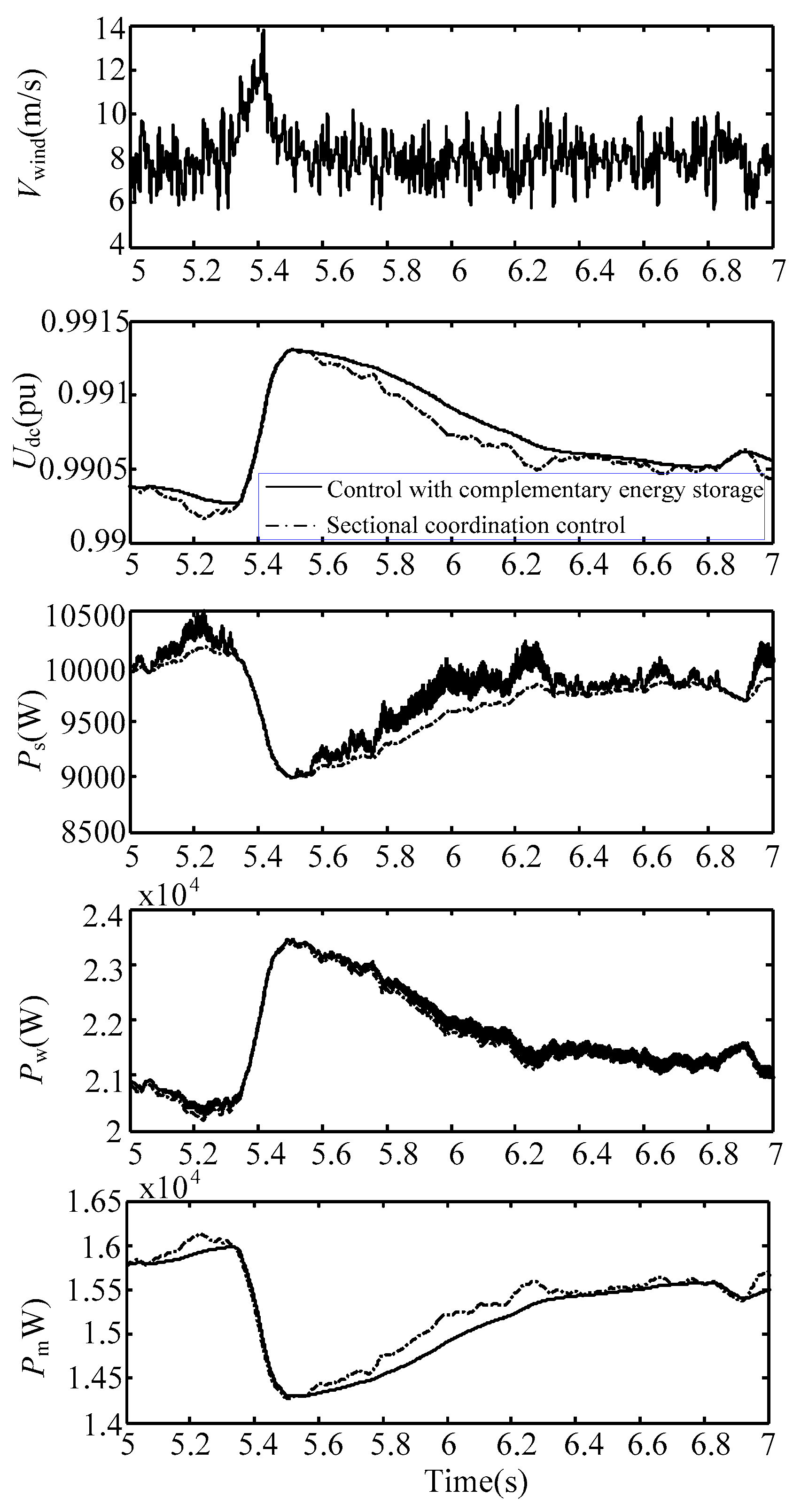
5.4. Simulation Analysis with Simulated Natural Wind Speed Similar to the Actual One

To simulate the actual wind speed, the superposition of basic wind, gust wind, and random wind was adopted as wind time series. The basic wind is a constant value, which was 7.5 m/s in this simulation. The gust wind vz and the random wind vn were obtained through the following Equation.
v z = 0.5 V zmax [ 1 cos 2 π ( t T I ) T g ] ,
v n = V nmax unifrnd ( 1 , 1 ) cos [ 2 π + unifrnd ( 0 , 2 π ) ] ,
where Vzmax and Vnmax represent the maxima of the gust wind and the random wind, respectively; TI and Tg are the start time and the cycle of the gust wind, respectively; and unifrnd (a, b) is a function that generates uniformly distributed random numbers with a and b as upper and lower bounds.
As is shown in Figure 15, the output of wind power presented fluctuating characteristics. When basic coordination control was adopted, DC voltage was disturbed by the fluctuating power. Although the voltage could still be maintained above 0.98 pu, fluctuating voltage will adversely affect voltage-sensitive loads in forest areas, such as parameter detection devices, and reduce the quality of output power. When the hybrid energy storage method proposed in this paper was adopted, under fast predictive control of converter, the wind turbine unit and the energy storage systems provided corresponding power support for the system according to the change rate of DC voltage, with additional power output suppressing the random fluctuation. The proposed method ensured the stability of system power and improved the quality of the DC voltage.

6. Conclusions

A hybrid complementary energy storage control method in forest DC microgrid is proposed, in which wind turbine energy storage, the battery, and the supercapacitor coordinate under different working conditions. Firstly, according to the characteristics of batteries and supercapacitors, batteries are adopted as a long-term energy reserve to bear the low-frequency fluctuation, while supercapacitors are used to suppress the corresponding high-frequency component. In addition, predictive control of the converters is adopted to reduce control delay and ensure the effectiveness of the energy storage converters. Furthermore, the inertia enhancement control strategy of the wind turbine system was studied by utilizing the large rotating kinetic energy of wind turbines to suppress power disturbance in a timely way and improve the fault ride-through capacity.
Through simulations of the DC microgrid in forest area conducted in MATLAB/Simulink, conclusions can be drawn that by utilizing the hybrid complementary energy storage, fast power smoothing can be achieved so that power quality is improved compared with methods using traditional PI control or fixed droop control. In addition, fault ride-through capability was effectively enhanced compared with microgrid with single energy storage by inertia control of the wind power unit that utilizes the kinetic energy in wind turbine.

Author Contributions

M.Y. proposed the algorithm; M.Y. and J.Z. conceived and designed the experiments; M.Y. and J.Z. performed the experiments; M.Y. and H.L. wrote the paper.

Funding

Project supported by funding for fundamental research business expenses of central universities (Grant No. BLX201716).

Conflicts of Interest

The authors declare no conflict of interest.

Nomenclature

ibat(k)Current of the battery at the kth moment
isc(k)Current of the supercapacitor at the kth moment
PwPower generated by the wind turbine.
PscPower of the supercapacitor.
PbPower of the battery.
PmPower generated by the biomass unit.
PliPower consumed by load i.
P*optReference power of the wind power system
UdcDC voltage of the main DC bus
Udc_mDC voltage at the outlet of the biomass unit
Udc_wDC voltage at the outlet of the wind power unit
Udc_bDC voltage at the outlet of the battery unit
Udc_lDC voltage at the outlet of load
Udc_stoDC voltage at the outlet of energy storage unit
U*dc_stoReference value of the DC voltage at the outlet of energy storage unit
ubat(k)Voltage of the battery at the kth moment
udc_bat(k)DC side voltage of the battery converter at the kth moment
usc(k)Voltage of the supercapacitor at the kth moment
udc_sc(k)DC side voltage of the supercapacitor converter at the kth moment

References

  1. Jodi, S.B.; Van, B.; Schwab, T.K.; Volker, C.R. The relative effectiveness of protected areas, a logging ban, and sacred areas for old-growth forest protection in southwest China. Biol. Conserv. 2015, 181, 1–8. [Google Scholar]
  2. González, J.; Arnau, R.R.J.; Rius, C.A. Optimal sizing of a hybrid grid-connected photovoltaic–wind–biomass power system. Appl. Energy 2015, 154, 752–762. [Google Scholar] [CrossRef]
  3. Teixeira, R.T.; Santos, A.R.D.; Marcatti, G.E. Forest biomass power plant installation scenarios. Biomass. Bioenerg. 2018, 108, 35–47. [Google Scholar] [CrossRef]
  4. Soliño, M.; Prada, A.; Vázquez, M.X. Green electricity externalities: forest biomass in an Atlantic European Region. Biomass. Bioenerg. 2009, 33, 407–414. [Google Scholar] [CrossRef]
  5. Martin, C.; Rocco, H.; Brandon, S. Climate change and power security: power load prediction for rural electrical microgrids using long short term memory and artificial neural networks. Appl. Sci. 2018, 8, 749. [Google Scholar]
  6. Schonberger, J.; Duke, R.; Round, S.D. DC-bus signaling: a distributed control strategy for a hybrid renewable nanogrid. IEEE Trans. Ind. Electron. 2006, 53, 1453–1460. [Google Scholar] [CrossRef]
  7. Peng, W.; Feng, C.; Che, A. Bi-Objective scheduling of fire engines for fighting forest fires: new optimization approaches. IEEE Trans. Intell. Transp. Syst. 2017, 99, 1–12. [Google Scholar]
  8. Park, H.; Turner, N.; Higgs, E. Exploring the potential of food forestry to assist in ecological restoration in North America and beyond. Restor. Ecol. 2017, 26, 284–293. [Google Scholar] [CrossRef]
  9. Kowalczyk, I. Barriers to the expansion of electrical cogeneration by the wood products industry in the United States. J. Sustain. Forest. 2013, 32, 159–174. [Google Scholar] [CrossRef]
  10. Busarello, T.D.C.; Paredes, H.K.M.; Pomilio, J.A. Synergistic operation between battery energy storage and photovoltaic generator systems to assist management of microgrids. IET. Gener. Transm. Dis. 2018, 12, 2944–2951. [Google Scholar] [CrossRef] [Green Version]
  11. Tan, M.; Cintuglu, M.H.; Mohammed, O.A. Control of a hybrid AC/DC microgrid involving energy storage and pulsed loads. IEEE Trans. Ind. Appl. 2017, 53, 567–575. [Google Scholar]
  12. Karavas, C.S.; Arvanitis, K.G.; Kyriakarakos, G. A novel autonomous PV powered desalination system based on a DC microgrid concept incorporating short-term energy storage. Sol. Energy 2018, 159, 947–961. [Google Scholar] [CrossRef]
  13. Sun, X.; Hao, Y.; Wu, Q. A multifunctional and wireless droop control for distributed energy storage units in islanded AC microgrid applications. IEEE Trans. Power. Electr. 2017, 32, 736–751. [Google Scholar] [CrossRef]
  14. Korada, N.; Mishra, M.K. Grid adaptive power management strategy for an integrated microgrid with hybrid energy storage. IEEE Trans. Ind. Electron. 2017, 64, 2884–2892. [Google Scholar] [CrossRef]
  15. Garcia-Torres, F.; Bordons, C. Optimal economical schedule of hydrogen-based microgrids with hybrid storage using model predictive control. IEEE Trans. Ind. Electron. 2015, 62, 5195–5207. [Google Scholar] [CrossRef]
  16. Garcia-Torres, F.; Bordons, C.; Ridao, M.A. Optimal economic schedule for a network of microgrids with hybrid energy storage system using distributed model predictive control. IEEE Trans. Ind. Electron. 2019, 66, 1919–1929. [Google Scholar] [CrossRef]
  17. Garcia-Torres, F.; Valverde, L.; Bordons, C. Optimal load sharing of hydrogen-based microgrids with hybrid storage using model-predictive control. IEEE Trans. Ind. Electron. 2016, 63, 4919–4928. [Google Scholar] [CrossRef]
  18. Xiao, J.; Peng, W.; Setyawan, L. Hierarchical control of hybrid energy storage system in DC microgrids. IEEE Trans. Ind. Electron. 2015, 62, 4915–4924. [Google Scholar] [CrossRef]
  19. Xu, Q.; Hu, X.; Peng, W. A decentralized dynamic power sharing strategy for hybrid energy Storage system in autonomous DC microgrid. IEEE Trans. Ind. Electron. 2017, 64, 5930–5941. [Google Scholar] [CrossRef]
  20. Hosseinzadeh, M.; Salmasi, F.R. Robust optimal power management system for a hybrid AC/DC micro-grid. IEEE Trans. Sustain. Energ. 2015, 6, 675–687. [Google Scholar] [CrossRef]
  21. Hosseinzadeh, M.; Salmasi, F.R. Fault-tolerant supervisory controller for a hybrid AC/DC micro-grid. IEEE Trans. Smart Grid 2018, 9, 2809–2823. [Google Scholar] [CrossRef]
  22. Chang, X.; Li, Y.; Xuan, L. An active damping method based on a supercapacitor energy storage system to overcome the destabilizing effect of instantaneous constant power loads in DC microgrids. IEEE Trans. Energy Conver. 2017, 32, 36–47. [Google Scholar] [CrossRef]
  23. Zhang, Y.; Yun, W.L. Energy management strategy for supercapacitor in droop-controlled DC microgrid using virtual impedance. IEEE Trans. Power. Electr. 2017, 32, 2704–2716. [Google Scholar] [CrossRef]
  24. Awad, E.A.; Badran, E.A.; Youssef, F.H. Mitigation of switching overvoltages in microgrids based on SVC and supercapacitor. IET. Gener. Transm. Dis. 2017, 12, 355–362. [Google Scholar] [CrossRef]
  25. Lu, X.; Sun, K.; Guerrero, J.M. Stability enhancement based on virtual impedance for DC microgrids with constant power loads. IEEE Trans. Smart Grid 2017, 6, 2770–2783. [Google Scholar] [CrossRef]
  26. Bui, T.; Kim, C.H.; Kim, K.H.; Sang, B.R. A modular cell balancer based on multi-winding transformer and switched-capacitor circuits for a series-connected battery string in electric vehicles. Appl. Sci. 2018, 8, 1278. [Google Scholar] [CrossRef]
  27. Worku, M.Y.; Abido, M.A.; Iravani, R. Power fluctuation minimization in grid connected photovoltaic using supercapacitor energy storage system. J. Renew. Sustain. Energy 2016, 8, 013501. [Google Scholar] [CrossRef]
  28. Kim, S.K.; Chang, R.P.; Kim, J.S. A stabilizing model predictive controller for voltage regulation of a DC/DC boost converter. IEEE Trans. Control Syst. Technol. 2014, 22, 2016–2023. [Google Scholar] [CrossRef]
Figure 1. System structure of DC microgrid with wind turbine, energy storage, and biomass energy.
Applsci 09 02523 g001
Figure 2. Basic principle of operation mode-based sectional coordinated control strategy for DC microgrid in forest: (a) Biomass power generation unit; (b) Energy storage unit; (c) Wind power unit/Load.
Applsci 09 02523 g002
Figure 3. State switching diagram of system control mode. ki (i = 1…8): the hysteresis bandwidth in different modes.
Applsci 09 02523 g003
Figure 4. Principle diagram of self-adaptive inertia droop control.
Applsci 09 02523 g004
Figure 5. Topology and working mode of bi-directional DC/DC converter in Boost mode: (a) Conduction period of V2; (b) Shutdown period of V2.
Applsci 09 02523 g005
Figure 6. Predictive control model of an energy storage system adopting adaptive droop control in the outer loop.
Applsci 09 02523 g006
Figure 7. Control block diagram of the hybrid energy storage system.
Applsci 09 02523 g007
Figure 8. Switching principle of improved MPPT curve.
Applsci 09 02523 g008
Figure 9. Principle diagram of self-adaptive speed control of wind power system.
Applsci 09 02523 g009
Figure 10. Comparison diagram of the basic control and the improved control of hybrid complementary energy storage.
Applsci 09 02523 g010
Figure 11. Operation mode judgment through voltage hysteresis.
Applsci 09 02523 g011
Figure 12. Overall control of the islanded DC microgrid in a forest area.
Applsci 09 02523 g012
Figure 13. Performance of each unit in the DC microgrid under fault condition in the biomass unit: (a) The solid lines were obtained by using the improved method of hybrid complementary energy storage based on prediction and the dotted lines were obtained utilizing the basic coordinated control; (b) The solid lines were obtained by using the improved method based on PI control and the dotted lines were obtained utilizing the basic coordinated control.
Applsci 09 02523 g013
Figure 14. Performance of each unit in the DC microgrid with fluctuating load: (a) The solid lines were obtained by using the improved method of hybrid complementary energy storage based on prediction and the dotted lines were obtained utilizing the basic coordinated control; (b) The solid lines were obtained by using the improved method based on PI control and the dotted lines were obtained utilizing the basic coordinated control.
Applsci 09 02523 g014
Figure 15. Performance of each unit in DC microgrid with simulated natural wind speed.
Applsci 09 02523 g015
Table 1. System parameters.
VariableSymbolValue
Rated power of micro-gas turbine systemPmN65 kW
Rated voltage of micro-gas turbineUmN400 V
Rated voltage of batteryUbN180 V
Rated capacity of batteryPbN100 A h
Rated capacity of battery converterPb_DCN40 kW
Rated capacity of supercapacitor converterPSCN40 kW
Rated speed of the wind turbineωN75 r/min
Number of wind turbineNw2
Rated capacity of the wind turbinePwN50 kW
Rated voltage of DC busUdcN400 V
Sampling periodTs50 μs

