Driving Mechanisms, Motion, and Mechanics of Screw Drive In-Pipe Robots: A Review


Abstract
1. Introduction
- Climbs vertical pipelines with ease
- Is easily sealed off
- Does not damage the inner wall, as it does not drag its body
- Has flexible movement
- Does not block the fluid flow inside the pipe
- Can adapt to changes in inner pipe diameter
- Has wider contact area than other robot types, which may dissipate contact force to generate propulsive force
- Is generally difficult to back-drive (e.g., screw locomotion robots) due to its angled wheels or tracks and is thus effective in high-flow networks
2. Mechanisms and Driving Principle
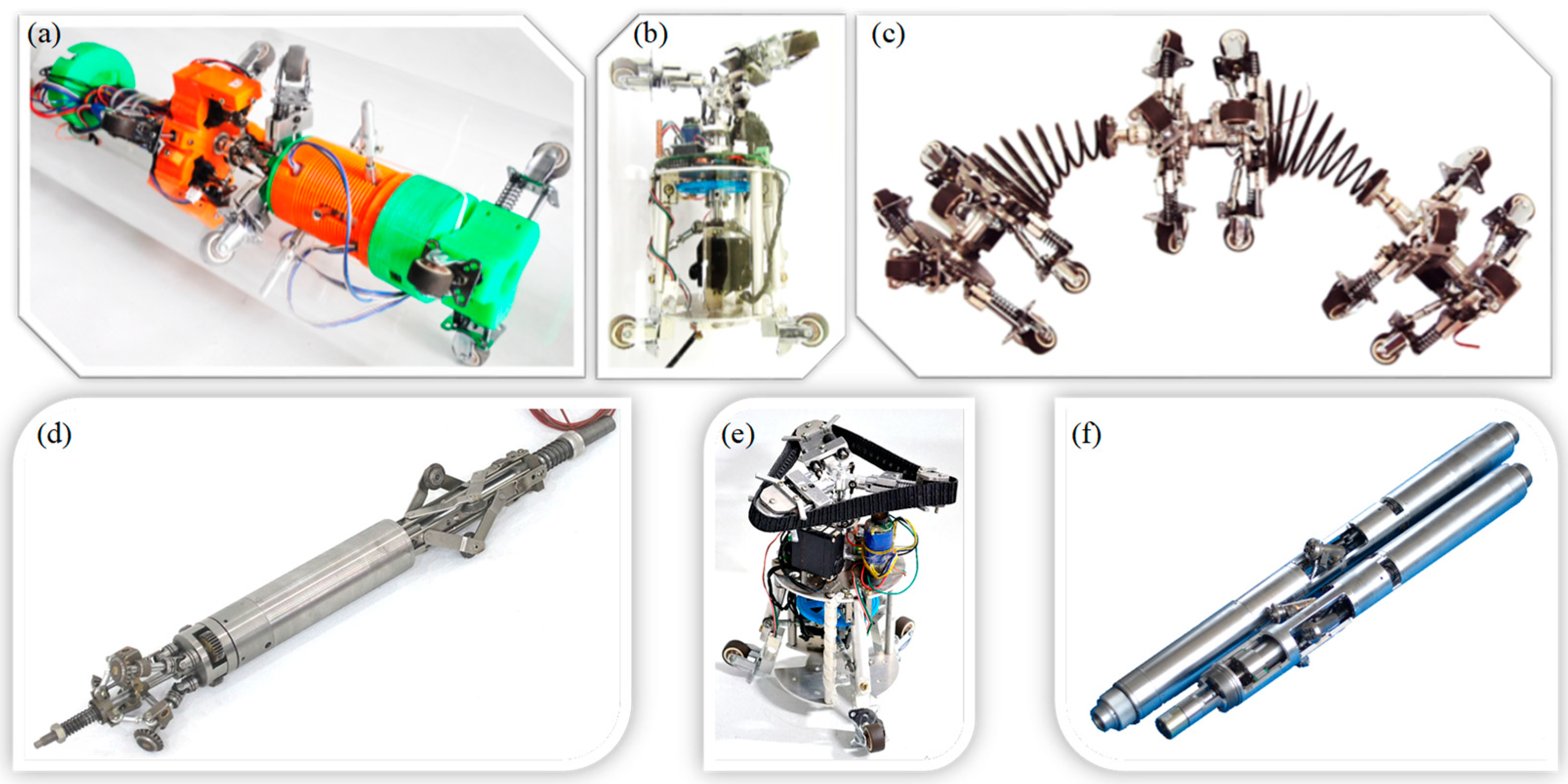
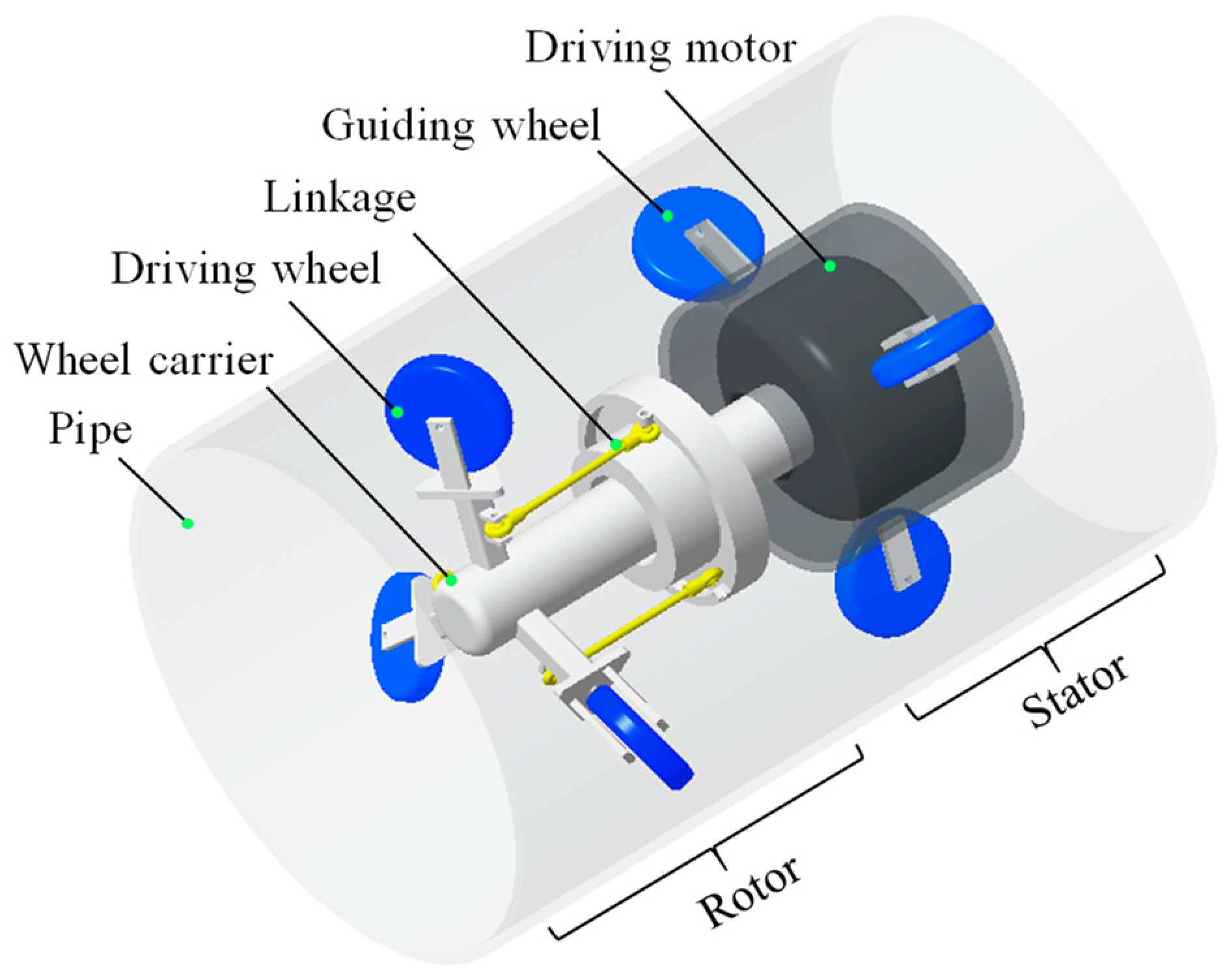
2.1. PSDIR
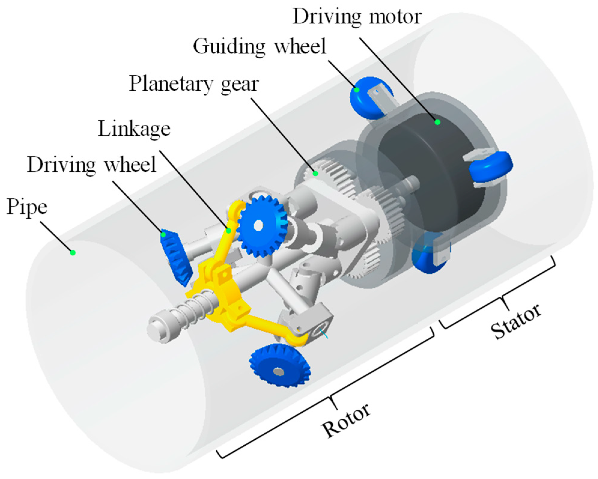
2.2. ASDIR
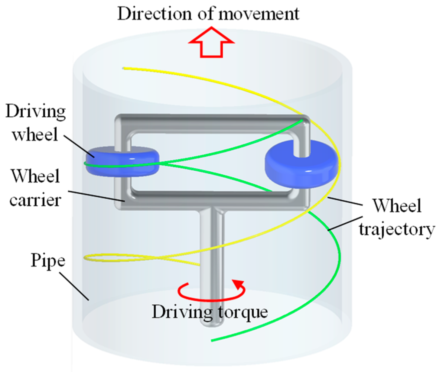
3. Motion Behavior
4. Mechanical Behavior
4.1. PSDIR
4.2. ASDIR
5. Summary
6. Conclusions
Author Contributions
Funding
Conflicts of Interest
References
- Ramírez-Camacho, J.G.; Carbone, F.; Pastor, E.; Bubbico, R.; Casal, J. Assessing the consequences of pipeline accidents to support land-use planning. Saf. Sci. 2017, 97, 34–42. [Google Scholar] [CrossRef]
- Liu, Q.; Ren, T.; Chen, Y. Characteristic analysis of a novel in-pipe driving robot. Mechatronics 2013, 23, 419–428. [Google Scholar] [CrossRef]
- Bubbico, R.; Carbone, F.; Ramírez-Camacho, J.G.; Pastor, E.; Casal, J. Conditional probabilities of post-release events for hazardous materials pipelines. Process Saf. Environ. Protect. 2016, 104, 95–110. [Google Scholar] [CrossRef]
- Siler-Evans, K.; Hanson, A.; Sunday, C.; Leonard, N.; Tumminello, M. Analysis of pipeline accidents in the United States from 1968 to 2009. Int. J. Crit. Infrastruct. Protect. 2014, 7, 257–269. [Google Scholar] [CrossRef]
- Schempf, H.; Mutschler, E.; Gavaert, A.; Skoptsov, G.; Crowley, W. Visual and nondestructive evaluation inspection of live gas mains using the Explorer™ family of pipe robots. J. Field Robot. 2010, 27, 217–249. [Google Scholar] [CrossRef]
- Mills, G.; Jackson, A.; Richardson, R. Advances in the Inspection of Unpiggable Pipelines. Robotics 2017, 6, 36. [Google Scholar] [CrossRef]
- An, J.; Lee, G.; Oh, I.; Moon, H.; Ryew, S. Navigation-oriented design for in-pipe robot in recursively divided sampling space with rapidly exploring random tree. J. Mech. Sci. Technol. 2017, 31, 5987–5995. [Google Scholar] [CrossRef]
- Datta, S.; Sarkar, S. A review on different pipeline fault detection methods. J. Loss Prev. Process Ind. 2016, 41, 97–106. [Google Scholar] [CrossRef]
- Song, Z.; Ren, H.; Zhang, J.; Ge, S.S. Kinematic analysis and motion control of wheeled mobile robots in cylindrical workspaces. IEEE Trans. Autom. Sci. Eng. 2016, 13, 1207–1214. [Google Scholar] [CrossRef]
- Hansen, P.; Alismail, H.; Rander, P.; Browning, B. Visual mapping for natural gas pipe inspection. Int. J. Robot. Res. 2015, 34, 532–558. [Google Scholar] [CrossRef]
- Hayat, A.; Elangovan, K.; Rajesh Elara, M.; Teja, M. Tarantula: Design, modeling, and kinematic identification of a quadruped wheeled robot. Appl. Sci. 2019, 9, 94. [Google Scholar] [CrossRef]
- Kim, H.M.; Choi, Y.S.; Lee, Y.G.; Choi, H.R. Novel mechanism for in-pipe robot based on a multiaxial differential gear mechanism. IEEE/ASME Trans. Mech. 2017, 22, 227–235. [Google Scholar] [CrossRef]
- Kakogawa, A.; Ma, S.; Hirose, S. An in-pipe robot with underactuated parallelogram crawler modules. In Proceedings of the 2014 IEEE International Conference on Robotics and Automation (ICRA), Hong Kong, China, 31 May–7 June 2014; pp. 1687–1692. [Google Scholar]
- Kwon, Y.S.; Yi, B.J. Development of a pipeline inspection robot system with diameter of 40 mm to 70 mm (Tbot-40). In Proceedings of the 2010 IEEE International Conference on Mechatronics and Automation, Xi’an, China, 4–7 August 2010; pp. 258–263. [Google Scholar]
- Mateos, L.A. LaMMos-Latching Mechanism based on Motorized-screw for Reconfigurable Robots and Exoskeleton Suits. arXiv 2017, arXiv:1801.00035. [Google Scholar]
- Kwon, Y.S.; Yi, B.J. Design and motion planning of a two-module collaborative indoor pipeline inspection robot. IEEE Trans. Robot. 2012, 28, 681–696. [Google Scholar] [CrossRef]
- Ren, T.; Liu, Q.; Li, Y.; Chen, Y. Design, analysis and innovation in variable radius active screw in-pipe drive mechanisms. Int. J. Adv. Robot. Syst. 2017, 14, 1–9. [Google Scholar] [CrossRef]
- Chen, Y.; Liu, Q.; Ren, T. A simple and novel helical drive in-pipe robot. Robotica 2015, 33, 920–932. [Google Scholar] [CrossRef]
- Li, P.; Ma, S.; Li, B.; Wang, Y.; Liu, Y. Self-rescue mechanism for screw drive in-pipe robots. In Intelligent Robots and Systems (IROS). In Proceedings of the 2010 IEEE/RSJ International Conference on Intelligent Robots and Systems, Taipei, Taiwan, 18–22 October 2010; pp. 2843–2849. [Google Scholar]
- Kakogawa, A.; Nishimura, T.; Ma, S. Designing arm length of a screw drive in-pipe robot for climbing vertically positioned bent pipes. Robotica 2016, 34, 306–327. [Google Scholar] [CrossRef]
- Tourajizadeh, H.; Rezaei, M.; Sedigh, A.H. Optimal Control of Screw In-pipe Inspection Robot with Controllable Pitch Rate. J. Intell. Robot. Syst. 2018, 90, 269–286. [Google Scholar] [CrossRef]
- Kamata, M.; Yamazaki, S.; Tanise, Y.; Yamada, Y.; Nakamura, T. Morphological change in peristaltic crawling motion of a narrow pipe inspection robot inspired by earthworm’s locomotion. Adv. Robot. 2018, 32, 386–397. [Google Scholar] [CrossRef]
- Nakazato, Y.; Sonobe, Y.; Toyama, S. Development of an in-pipe micro mobile robot using peristalsis motion. J. Mech. Sci. Technol. 2010, 24, 51–54. [Google Scholar] [CrossRef]
- Zagler, A.; Pfeiffer, F. “MORITZ” a pipe crawler for tube junctions. In Proceedings of the 2003 IEEE International Conference on Robotics and Automation (Cat. No.03CH37422), Taipei, Taiwan, 14–19 September 2003; Volume 3, pp. 2954–2959. [Google Scholar]
- Machado, J.T.; Silva, M.F. An overview of legged robots. In International Symposium on Mathematical Methods in Engineering; MME Press: Ankara, Turkey, 2017. [Google Scholar]
- Trebuna, F.; Virgala, L.; Pastor, M.; Liptak, T.; Mikova, L. An inspection of pipe by snake robot. Int. J. Adv. Robot. Syst. 2016, 13. [Google Scholar] [CrossRef]
- Granosik, G. Hypermobile robots–the survey. J. Intell. Robot. Syst. 2014, 75, 147–169. [Google Scholar] [CrossRef]
- Zhang, X.; Liu, J.; Ju, Z.; Yang, C. Head-raising of snake robots based on a predefined spiral curve method. Appl. Sci. 2018, 8, 2011. [Google Scholar] [CrossRef]
- Ismail, I.N.; Anuar, A.; Sahari, K.S.M.; Baharuddin, M.Z.; Fairuz, M.; Jalal, A.; Saad, J.M. Development of in-pipe inspection robot: A review. In Proceedings of the 2012 IEEE Conference on Sustainable Utilization and Development in Engineering and Technology (STUDENT), Kuala Lumpur, Malaysia, 6–9 October 2012; pp. 310–315. [Google Scholar]
- Ren, T.; Liu, Q.; Li, Y.; Chen, Y. Basic characteristics of a novel in-pipe helical drive robot. Int. J. Mechatron. Autom. 2014, 4, 127–136. [Google Scholar]
- Horodinca, M.; Doroftei, I.; Mignon, E.; Preumont, A. A simple architecture for in-pipe inspection robots. In Proceedings of the International Colloquium on Autonomous and Mobile Systems, Magdeburg, Germany, 25–26 June 2002; pp. 61–64. [Google Scholar]
- Kakogawa, A.; Nishimura, T.; Ma, S. Development of a screw drive in-pipe robot for passing through bent and branch pipes. In Proceedings of the 2013 44th International Symposium on Robotics (ISR), Seoul, Korea, 24–26 October 2013; pp. 1–6. [Google Scholar]
- Lee, D.; Park, J.; Hyun, D.; Yook, G.; Yang, H.S. Novel mechanisms and simple locomotion strategies for an in-pipe robot that can inspect various pipe types. Mech. Mach. Theory 2012, 56, 52–68. [Google Scholar] [CrossRef]
- Li, T.; Ma, S.; Li, B.; Wang, M.; Li, Z.; Wang, Y. Development of an in-pipe robot with differential screw angles for curved pipes and vertical straight pipes. J. Mech. Robot. 2017, 9, 051014. [Google Scholar] [CrossRef]
- Li, P.; Ma, S.; Lyu, C.; Jiang, X.; Liu, Y. Energy-efficient control of a screw-drive pipe robot with consideration of actuator’s characteristics. Robot. Biomim. 2016, 3, 11. [Google Scholar] [CrossRef]
- Li, P.; Tang, M.; Lyu, C.; Fang, M.; Duan, X.; Liu, Y. Design and analysis of a novel active screw-drive pipe robot. Adv. Mech. Eng. 2018, 10. [Google Scholar] [CrossRef]
- Ren, T.; Chen, Y.; Liu, Q. A helical drive in-pipe robot based on compound planetary gearing. Adv. Robot. 2014, 28, 1165–1175. [Google Scholar]
- Li, Y.; Liu, Q.; Chen, Y.; Ren, T. Design and analysis of an active helical drive downhole tractor. Chin. J. Mech. Eng. 2017, 2, 428–437. [Google Scholar] [CrossRef]
- Ren, T.; Liu, Q.; Chen, Y.; Ji, S. Variable pitch helical drive in-pipe robot. Int. J. Robot. Autom. 2016, 31, 263–271. [Google Scholar] [CrossRef]
- Liu, Q.; Chen, Y.; Ren, T.; Wei, Y. Optimized inchworm motion planning for a novel in-pipe robot. Proc. Inst. Mech. Eng. Part C J. Mech. Eng. Sci. 2014, 228, 1248–1258. [Google Scholar] [CrossRef]
- Li, Y.; Liu, Q.; Chen, Y.; Li, M. Helical-contact deformation measuring method in oil–gas pipelines. Int. J. Robot. Autom. 2017, 32. [Google Scholar] [CrossRef]
- Liu, Q.; Ren, T.; Chen, Y. Actively Driven Spiral Pipeline Robot. U.S. Patent 9,316,340, 19 April 2016. [Google Scholar]
- Xiao, X.; Murphy, R. A review on snake robot testbeds in granular and restricted maneuverability spaces. Robot. Auton. Syst. 2018, 110, 160–172. [Google Scholar] [CrossRef]
- HORODINCĂ, M.; PREUMONT, A.; BURDA, I. The heli-pipe inspection robots architecture for curved pipes. In Proceedings of the International Conference of Manufacturing Systems ICMS 2003, Ogun State, Nigeria, 16–22 November 2003; pp. 149–154. [Google Scholar]
- Nishimura, T.; Kakogawa, A.; Ma, S. Improvement of a screw drive in-pipe robot with pathway selection mechanism to pass through T-branches. J. Robot. Mechatron. 2013, 25, 340–346. [Google Scholar] [CrossRef]
- Fukushima, H.; Satomura, S.; Kawai, T.; Tanaka, M.; Kamegawa, T.; Matsuno, F. Modeling and control of a snake-like robot using the screw-drive mechanism. IEEE Trans. Robot. 2012, 28, 541–554. [Google Scholar] [CrossRef]
- Runete, A.; Hernando, M.; Gambao, E.; Torres, J.E. A behaviour-based control architecture for heterogeneous modular, multi-configurable, chained micro-robots. Robot. Auton. Syst. 2012, 60, 1607–1624. [Google Scholar] [CrossRef]
- Fukuda, T.; Hosokai, H.; Uemura, M. Rubber gas actuator driven by hydrogen storage alloy for in-pipe inspection mobile robot with flexible structure. In Proceedings of the 1989 International Conference on Robotics and Automation, Scottsdale, AZ, USA, 14–19 May 1989; pp. 1847–1852. [Google Scholar]
- Yabe, S.; Masuta, H.; Lim, H.O. New in-pipe robot capable of coping with various diameters. In Proceedings of the 2012 12th International Conference on Control, Automation and Systems, JeJu Island, Korea, 17–21 October 2012; pp. 151–156. [Google Scholar]
- Li, T.; Ma, S.; Li, B.; Wang, M.; Wang, Y. Axiomatic design method to design a screw drive in-pipe robot passing through varied curved pipes. Sci. China Technol. Sci. 2016, 59, 191–202. [Google Scholar] [CrossRef]
- Aligia, D.A.; Magallan, G.A.; De Angelo, C.H. EV Traction Control Based on Nonlinear Observers Considering Longitudinal and Lateral Tire Forces. IEEE Trans. Intell. Transp. Syst. 2018, 19, 2558–2571. [Google Scholar] [CrossRef]
- Ward, C.C.; Iagnemma, K. A dynamic-model-based wheel slip detector for mobile robots on outdoor terrain. IEEE Trans. Robot. 2008, 24, 821–831. [Google Scholar] [CrossRef]


| Ref NO. | Author Name | In-Pipe Geometry | Length (mm) | Weight (kg) | Diameter Range (mm) | Traction Force (N) | Application | ||
|---|---|---|---|---|---|---|---|---|---|
| Slope (°) | Elbow (°) | Branch | |||||||
| [2] | Liu Qingyou | 0 | 90 and 120 | None | Unk. | Unk. | 200 | Unk. | Gas and liquid |
| [17,37] | Tao Ren | Unk. | 90 | None | 730 | Unk. | 90–120 | 500 | Oil and gas |
| [19] | Pen Li | 0 | Unk. | None | 349 | 3.35 | 173–200 | Unk. | Other |
| [20,32,45] | Atsushi Kakogawa | 0 | 90 | T | 175.8 | 0.7 | 109–129 | Unk. | Other |
| [31] | Mihaita Horodinca | 0 | Unk. | None | Unk. | 1.3 | 170 | 5 | Other |
| 0.47 | 70 | 3 | |||||||
| 0.48 | 70 | 3 | |||||||
| 0.25 | 40 | 1 | |||||||
| [33] | Dongwoo Lee | 0 and 90 | 90 | T | 280 | 3.6 | 259–305 | Unk. | Other |
| [34,50] | Te Li | 0 and 90 | 45 and 90 | None | Unk. | 2.05 | Unk. | Unk. | Other |
| [38] | Yujia Li | Unk. | Unk. | None | 900 | Unk. | 105 | 1620 | Oil and gas |
| [39] | Tao Ren | Unk. | 135 | Unk. | 230 | Unk. | 160–210 | Unk. | Oil and gas |
| [47] | A. Brunete | 0, 30, 60 and 90 | 90 | None | About 215 | About 0.1 | 40 | Unk. | Other |
| [48] | Toshio Fukuda | 0 | 90 | T | 90–130 | 0.08 | 32–65 | 24 | Other |
| [49] | Sari Yabe | 90 | 90 | T | 215 | 1.85 | 180–220 | Unk. | Wastewater |
© 2019 by the authors. Licensee MDPI, Basel, Switzerland. This article is an open access article distributed under the terms and conditions of the Creative Commons Attribution (CC BY) license (http://creativecommons.org/licenses/by/4.0/).
Share and Cite
Ren, T.; Zhang, Y.; Li, Y.; Chen, Y.; Liu, Q. Driving Mechanisms, Motion, and Mechanics of Screw Drive In-Pipe Robots: A Review. Appl. Sci. 2019, 9, 2514. https://doi.org/10.3390/app9122514
Ren T, Zhang Y, Li Y, Chen Y, Liu Q. Driving Mechanisms, Motion, and Mechanics of Screw Drive In-Pipe Robots: A Review. Applied Sciences. 2019; 9(12):2514. https://doi.org/10.3390/app9122514
Chicago/Turabian StyleRen, Tao, Yin Zhang, Yujia Li, Yonghua Chen, and Qingyou Liu. 2019. "Driving Mechanisms, Motion, and Mechanics of Screw Drive In-Pipe Robots: A Review" Applied Sciences 9, no. 12: 2514. https://doi.org/10.3390/app9122514
APA StyleRen, T., Zhang, Y., Li, Y., Chen, Y., & Liu, Q. (2019). Driving Mechanisms, Motion, and Mechanics of Screw Drive In-Pipe Robots: A Review. Applied Sciences, 9(12), 2514. https://doi.org/10.3390/app9122514