Recent Advances and Applications of Semiconductor Photocatalytic Technology


Abstract
1. Introduction
2. Photocatalytic Mechanism and Influencing Factors
2.1. Reaction Mechanism
2.2. Influencing Factors
3. Common Classification of Photocatalysts
3.1. Oxide Photocatalyst
3.1.1. TiO2-Based Photocatalyst
3.1.2. Bi2O3-Based Photocatalyst
3.1.3. Other Oxide Photocatalysts
3.2. Non-Oxide Photocatalyst
3.2.1. CdS Series Photocatalyst
3.2.2. CuS Series Photocatalyst
3.2.3. ZnS Series Photocatalyst
3.2.4. Nitride Series Photocatalyst
4. Common Preparation Methods
4.1. Electrospinning
4.2. Solid Phase Method
4.3. Gas Phase Method
4.3.1. Chemical Vapor Deposition (CVD)
4.3.2. Physical Vapor Deposition (PVD)
4.3.3. Molecular Beam Epitaxy (MBE)
4.4. Liquid Phase Method
4.4.1. Sol–Gel Method
4.4.2. Precipitation Method
4.4.3. Liquid Deposition Method
4.4.4. Hydrothermal Method
5. Methods for Improving Photocatalytic Efficiency
5.1. Precious Metal Depositing
5.2. Semiconductor Compound
5.3. Metal or Non-Metal Ion Doping
5.3.1. Metal Ion Doping
5.3.2. Non-Metal Ion Doping
5.3.3. Mixed Doping
5.4. Surface Dye Photosensitization
6. Application
6.1. Photocatalytic Hydrogen Production
6.2. Wastewater Treatment
6.3. Photocatalytic Disinfection
6.4. Air Purification
7. Summary and Outlook
Acknowledgments
Funding
Conflicts of Interest
Abbreviations
| Full Name | Abbreviation |
| Valence band | VB |
| Conduction band | CB |
| Direct-current power supply | DC power supply |
| Physical vapor deposition | PVD |
| Chemical vapor deposition | CVD |
| Molecular beam epitaxy | MBE |
| RF magnetron sputtering | RF-MS |
| Ultraviolet irradiation | UV irradiation |
| Methyl orange | MB |
| Rhodamine B | RhB |
| Escherichia coli | E. coli |
| Benzoic acid | BA |
| Volatile organic compounds | VOCs |
References
- Brunekreef, B.; Holgate, S.T. Air pollution and health. Lancet 2002, 360, 1233–1242. [Google Scholar] [CrossRef]
- Fujishima, A.; Honda, K. Electrochemical photolysis of water at a semiconductor electrode. Nature 1972, 238, 37–38. [Google Scholar] [CrossRef] [PubMed]
- Frank, S.N.; Bard, A.J. Semiconductor electrodes. II. Electrochemistry at n-type titanium dioxide electrodes in acetonitrile solutions. J. Am. Chem. Soc. 1975, 97, 7427–7433. [Google Scholar] [CrossRef]
- Horie, Y.; David, D.A.; Taya, M.; Tone, S. Effects of light intensity and titanium dioxide concentration on photocatalytic sterilization rates of microbial cells. Ind. Eng. Chem. Res. 1996, 34, 3920–3926. [Google Scholar] [CrossRef]
- Jin, C.; Liu, X.; Tan, L.; Cui, Z.; Yang, X.; Zheng, Y.; Yeung, K.; Chu, P.K.; Wu, S. Ag/AgBr-loaded mesoporous silica for rapid sterilization and promotion of wound healing. Biomater. Sci. 2018, 6, 1735–1744. [Google Scholar] [CrossRef] [PubMed]
- Rong, W.; Zhang, W.; Zhu, W.; Yan, L.; Li, S.; Kai, C.; Na, H.; Suo, Y.; Wang, J. Enhanced visible-light-driven photocatalytic sterilization of tungsten trioxide by surface-engineering oxygen vacancy and carbon matrix. Chem. Eng. J. 2018, 348, 292–300. [Google Scholar]
- Li, Q.; Guo, B.; Yu, J.; Ran, J.; Zhang, B.; Yan, H.; Gong, J.R. Highly efficient visible-light-driven photocatalytic hydrogen production of CdS-cluster-decorated graphene nanosheets. J. Am. Chem. Soc. 2011, 133, 10878–10884. [Google Scholar] [CrossRef] [PubMed]
- Chu, J.; Han, X.; Yu, Z.; Du, Y.; Song, B.; Xu, P. Highly efficient visible-light-driven photocatalytic hydrogen production on CdS/Cu7S4/g-C3N4 ternary heterostructures. ACS Appl. Mater. Interfaces 2018, 10, 20404–20411. [Google Scholar] [CrossRef]
- Wang, R.; Shuang, N.; Gang, L.; Xu, X. Hollow CaTiO3 cubes modified by La/Cr co-doping for efficient photocatalytic hydrogen production. Appl. Catal. B Environ. 2018, 225, 139–147. [Google Scholar] [CrossRef]
- Wei, R.B.; Huang, Z.L.; Gu, G.H.; Zhu, W.; Zeng, L.; Chen, Y.; Liu, Z.Q. Dual-cocatalysts decorated rimous cds spheres advancing highly-efficient visible-light photocatalytic hydrogen production. Appl. Catal. B Environ. 2018, 231, 101–107. [Google Scholar] [CrossRef]
- Zhang, H.; Lin, J.; Li, Z.; Li, T.; Jia, X.; Wu, X.L.; Hu, S.; Lin, H.; Chen, J.; Zhu, J. Organic dye doped graphitic carbon nitride with a tailored electronic structure for enhanced photocatalytic hydrogen production. Catal. Sci. Technol. 2019, 9, 502–508. [Google Scholar] [CrossRef]
- Liu, Q.; Zhou, Y.; Kou, J.; Chen, X.; Tian, Z.; Gao, J.; Yan, S.; Zou, Z. High-yield synthesis of ultralong and ultrathin Zn2GeO4 nanoribbons toward improved photocatalytic reduction of CO2 into renewable hydrocarbon fuel. J. Am. Chem. Soc. 2010, 132, 14385–14387. [Google Scholar] [CrossRef] [PubMed]
- Chen, L.; Qin, Y.; Chen, G.; Li, M.; Cai, L.; Qiu, Y.; Fan, H.; Robert, M.; Lau, T.C. A molecular noble metal-free system for efficient visible light-driven reduction of CO2 to CO. Dalton Trans. 2019. [Google Scholar] [CrossRef]
- Tan, W.; Cao, B.; Xiao, W.; Zhang, M.; Wang, S.; Xie, S.; Xie, D.; Cheng, F.; Guo, Q.; Liu, P. Electrochemical reduction of CO2 on hollow cubic Cu2O@Au nanocomposites. Nanoscale Res. Lett. 2019, 14, 63–69. [Google Scholar] [CrossRef] [PubMed]
- Vidyasagar, D.; Manwar, N.; Gupta, A.; Ghugal, S.G.; Umare, S.S.; Boukherroub, R. Phenyl-grafted carbon nitride semiconductor for photocatalytic CO2-reduction and rapid degradation of organic dyes. Catal. Sci. Technol. 2019, 9, 822–832. [Google Scholar] [CrossRef]
- Hofstadler, K.; Bauer, R.; Novalic, S.; Heisler, G. New reactor design for photocatalytic wastewater treatment with TiO2 immobilized on fused-silica glass fibers: Photomineralization of 4-chlorophenol. Environ. Sci. Technol. 1994, 28, 670–674. [Google Scholar] [CrossRef] [PubMed]
- Li, F.B.; Li, X.Z. Photocatalytic properties of gold/gold ion-modified titanium dioxide for wastewater treatment. Appl. Catal. A Gen. 2002, 228, 15–27. [Google Scholar] [CrossRef]
- Choi, H.; Stathatos, E.; Dionysiou, D.D. Photocatalytic TiO2 films and membranes for the development of efficient wastewater treatment and reuse systems. Desalination 2007, 202, 199–206. [Google Scholar] [CrossRef]
- Vaiano, V.; Iervolino, G. Facile method to immobilize ZnO particles on glass spheres for the photocatalytic treatment of tannery wastewater. J. Colloid Interface Sci. 2018, 518, 192–199. [Google Scholar] [CrossRef]
- Betancourt-Buitrago, L.A.; Ossa-Echeverry, O.E.; Rodriguez-Vallejo, J.C.; Barraza, J.M.; Marriaga, N.; Machuca-Martínez, F. Anoxic photocatalytic treatment of synthetic mining wastewater using TiO2 and scavengers for complexed cyanide recovery. Photochem. Photobiol. Sci. 2019, 18, 853–862. [Google Scholar] [CrossRef]
- Fu, X.; Zeltner, W.A.; Anderson, M.A. Applications in photocatalytic purification of air. Stud. Surf. Sci. Catal. 1997, 103, 445–461. [Google Scholar]
- Besov, A.S.; Vorontsov, A.V.; Parmon, V.N. Fast adsorptive and photocatalytic purification of air from acetone and dimethyl methylphosphonate by TiO2 aerosol. Appl. Catal. B Environ. 2009, 89, 602–612. [Google Scholar] [CrossRef]
- Kako, T.; Ichihara, F.; Liu, G.; Meng, X.; Ye, J. Study on the enhancement of photocatalytic environment purification through ubiquitous-red-clay loading. SN Appl. Sci. 2019, 1, 138–145. [Google Scholar] [CrossRef]
- Boyjoo, Y.; Sun, H.; Liu, J.; Pareek, V.K.; Wang, S. A review on photocatalysis for air treatment: From catalyst development to reactor design. Chem. Eng. J. 2017, 310, 537–559. [Google Scholar] [CrossRef]
- Wang, W.; Tadé, M.O.; Shao, Z. Nitrogen-doped simple and complex oxides for photocatalysis: A review. Prog. Mater. Sci. 2018, 92, 33–63. [Google Scholar] [CrossRef]
- Li, X.; Yu, J.; Wageh, S.; Al-Ghamdi, A.A.; Xie, J. Graphene in photocatalysis: A review. Small 2016, 12, 6640–6696. [Google Scholar] [CrossRef] [PubMed]
- Zhou, P.; Yu, J.; Jaroniec, A. All-solid-state Z-scheme photocatalytic systems. Adv. Mater. 2014, 26, 4920–4935. [Google Scholar] [CrossRef]
- Wang, W.; Li, G.; Xia, D.; An, T.; Zhao, H.; Wong, P.K. Photocatalytic nanomaterials for solar-driven bacterial inactivation: Recent progress and challenges. Environ. Sci. Nano 2017, 4, 782–799. [Google Scholar] [CrossRef]
- Sayama, K.; Yase, K.; Arakawa, H.; Asakura, K.; Tanaka, A.; Domen, K.; Onishi, T. Photocatalytic activity and reaction mechanism of Pt-intercalated K4Nb6O17 catalyst on the water splitting in carbonate salt aqueous solution. J. Photochem. Photobiol. A 1998, 114, 125–135. [Google Scholar] [CrossRef]
- Kawai, M.; Kawai, T.; Naito, S.; Tamaru, K. The mechanism of photocatalytic reaction over Pt/TiO2: Production of H2 and aldehyde from gaseous alcohol and water. Chem. Phys. Lett. 1984, 110, 58–62. [Google Scholar] [CrossRef]
- And, J.S.; Rabani, J. Photocatalytic dechlorination of aqueous carbon tetrachloride solutions in TiO2 layer systems: A chain reaction mechanism. Z. Phys. Chem. 1998, 1, 313–318. [Google Scholar]
- Tan, T.T.Y.; Donia Beydoun, A.; Amal, R. Photocatalytic reduction of Se(vi) in aqueous solutions in UV/TiO2 system: Kinetic modeling and reaction mechanism. J. Phys. Chem. B 2003, 107, 4296–4303. [Google Scholar] [CrossRef]
- Yamazaki, S.; Toshifumi Tanimura, A.; Yoshida, A.; Hori, K. Reaction mechanism of photocatalytic degradation of chlorinated ethylenes on porous TiO2 pellets: Cl radical-initiated mechanism. J. Phys. Chem. A 2004, 108, 5183–5188. [Google Scholar] [CrossRef]
- Zhao, L.H.; Itoh, K.; Murabayashi, M. Reaction mechanism of photocatalytic oxidation of trichloroethylene on TiO2 film. Chin. J. Catal. 2004, 25, 915–919. [Google Scholar]
- Li, A.C.; Li, G.H.; Zheng, Y.; Feng, L.L.; Zheng, Y.J. Photocatalytic property and reaction mechanism of (Ni-Mo)/TiO2 nano thin film evaluated with congo red. Acta Phys.-Chim. Sin. 2012, 28, 457–464. [Google Scholar]
- Moctezuma, E.; Leyva, E.; Aguilar, C.A.; Luna, R.A.; Montalvo, C. Photocatalytic degradation of paracetamol: Intermediates and total reaction mechanism. J. Hazard. Mater. 2012, 243, 130–138. [Google Scholar] [CrossRef]
- Nishikawa, M.; Mitani, Y.; Nosaka, Y. Photocatalytic reaction mechanism of Fe(III)-grafted TiO2 studied by means of ESR spectroscopy and chemiluminescence photometry. J. Phys. Chem. C 2012, 116, 14900–14907. [Google Scholar] [CrossRef]
- Liu, L.; Li, Y. Understanding the reaction mechanism of photocatalytic reduction of CO2 with H2O on TiO2-based photocatalysts: A review. Aerosol Air Qual. Res. 2014, 14, 453–469. [Google Scholar] [CrossRef]
- Guzman, M.I.; Martin, S.T. Oxaloacetate-to-malate conversion by mineral photoelectrochemistry: Implications for the viability of the reductive tricarboxylic acid cycle in prebiotic chemistry. Int. J. Astrobiol. 2008, 7, 271–278. [Google Scholar] [CrossRef]
- Zhou, R.; Guzman, M.I. CO2 reduction under periodic illumination of ZnS. J. Phys. Chem. C 2014, 118, 11649–11656. [Google Scholar] [CrossRef]
- Kim, S.-J.; Lee, E.G.; Park, S.D.; Jeon, C.J.; Cho, Y.H.; Rhee, C.K.; Kim, W.W. Photocatalytic effects of rutile phase TiO2 ultrafine powder with high specific surface area obtained by a homogeneous precipitation process at low temperatures. J. Sol-Gel Sci. Technol. 2001, 22, 63–74. [Google Scholar] [CrossRef]
- Liu, C.; Han, X.; Xie, S.; Kuang, Q.; Wang, X.; Jin, M.; Xie, Z.; Zheng, L. Enhancing the photocatalytic activity of anatase TiO2 by improving the specific facet-induced spontaneous separation of photogenerated electrons and holes. Chemistry 2013, 8, 282–289. [Google Scholar]
- Kapinus, E.I.; Khalyavka, T.A.; Shimanovskaya, V.V.; Viktorova, T.I.; Strelko, V.V. Photocatalytic activity of spectro-pure titanium dioxide: Effects of crystalline structure, specific surface area and sorption properties. Int. J. Photoenergy 2014, 5, 159–166. [Google Scholar] [CrossRef]
- Si, W.; Yang, Z.; Wang, X.; Lv, Q.; Huang, C. Fe, N-odoped graphdiyne displaying efficient oxygen reduction reaction activity. ChemSusChem 2018, 12, 173–178. [Google Scholar] [CrossRef] [PubMed]
- Ji-Lian, L.I. The influence factors of photocatalytic oxidation cyclohexance over nano-ZnFe2O4/SiO2. J. Dalian Coll. Educ. 2001, 17, 54–55. [Google Scholar]
- Barka, N.; Qourzal, S.; Assabbane, A.; Nounah, A.; Ait-Ichou, Y. Factors influencing the photocatalytic degradation of rhodamine b by TiO2-coated non-woven paper. J. Photochem. Photobiol. A 2008, 195, 346–351. [Google Scholar] [CrossRef]
- Liu, H.; Pei, S.; Liu, G.; Chen, Y. Study on the influencing factors of photocatalytic degradation of X-3B aqueous solution by TiO2 fibers. Acta Sci. Circumstantiae 2012, 32, 1054–1059. [Google Scholar]
- Hoque, M.; Guzman, M. Photocatalytic activity: Experimental features to report in heterogeneous photocatalysis. Materials 2011, 11, 1990–2000. [Google Scholar] [CrossRef] [PubMed]
- Eggins, B.R.; Robertson, P.K.J.; Murphy, E.P.; Woods, E.; Irvine, J.T.S. Factors affecting the photoelectrochemical fixation of carbon dioxide with semiconductor colloids. J. Photochem. Photobiol. A 1998, 118, 31–40. [Google Scholar] [CrossRef]
- Guzman, M.I.; Martin, S.T. Photo-production of lactate from glyoxylate: How minerals can facilitate energy storage in a prebiotic world. Chem. Commun. 2010, 46, 2265–2267. [Google Scholar] [CrossRef] [PubMed]
- Zhang, X.V.; Martin, S.T. Driving parts of krebs cycle in reverse through mineral photochemistry. J. Am. Chem. Soc. 2006, 128, 16032–16033. [Google Scholar] [CrossRef] [PubMed]
- Zhou, R.; Guzman, M.I. Photocatalytic reduction of fumarate to succinate on ZnS mineral surfaces. J. Phys. Chem. C 2016, 120, 7349–7357. [Google Scholar] [CrossRef]
- Fujishima, A.; Zhang, X.; Tryk, D.A. Tio photocatalysis and related surface phenomena. Surf. Sci. Rep. 2008, 63, 515–582. [Google Scholar] [CrossRef]
- Hashimoto, K.; Irie, H.; Fujishima, A. TiO2 photocatalysis: A historical overview and future prospects. Jpn. J. Appl. Phys. 2005, 44, 8269–8285. [Google Scholar] [CrossRef]
- Sakthivel, S.; Kisch, H. Daylight photocatalysis by carbon-modified titanium dioxide. Angew. Chem. Int. Ed. 2003, 42, 4908–4911. [Google Scholar] [CrossRef] [PubMed]
- Linsebigler, A.L.; Lu, G.; Yates, J.T. Photocatalysis on TiO2 surfaces: Principles, mechanisms, and selected results. Chem. Rev. 1995, 95, 735–758. [Google Scholar] [CrossRef]
- Fujishima, A.; Hashimoto, K.; Watanabe, T. TiO2 photocatalysis: Fundamentals and applications. In A Revolution in Cleaning Technology; BKC, Inc.: Tokyo, Japan, 1999; pp. 14–21. [Google Scholar]
- Woan, K.; Pyrgiotakis, G.; Sigmund, W. Photocatalytic carbon-nanotube–TiO2 composites. Adv. Mater. 2009, 21, 2233–2239. [Google Scholar] [CrossRef]
- Jodat, A.; Jodat, A. Photocatalytic degradation of chloramphenicol and tartrazine using Ag/TiO2 nanoparticles. Desalin. Water Treat. 2014, 52, 2668–2677. [Google Scholar] [CrossRef]
- Pan, J.H.; Cai, Z.; Yu, Y.; Zhao, X.S. Controllable synthesis of mesoporous f-TiO2 spheres for effective photocatalysis. J. Mater. Chem. 2011, 21, 11430–11438. [Google Scholar] [CrossRef]
- Mu, W.; Herrmann, J.-M.; Pichat, P. Room temperature photocatalytic oxidation of liquid cyclohexane into cyclohexanone over neat and modified TiO2. Catal. Lett. 1989, 3, 73–84. [Google Scholar] [CrossRef]
- Izumi, I.; Dunn, W.W.; Wilbourn, K.O.; Fan, F.R.F.; Bard, A.J. Heterogeneous photocatalytic oxidation of hydrocarbons on platinized titanium dioxide powders. J. Phys. Chem. 1980, 84, 3207–3210. [Google Scholar] [CrossRef]
- Huang, M.; Yu, J.; Li, B.; Deng, C.; Wang, L.; Wu, W.; Dong, L.; Zhang, F.; Fan, M. Intergrowth and coexistence effects of TiO2–SnO2 nanocomposite with excellent photocatalytic activity. J. Alloys Compd. 2015, 629, 55–61. [Google Scholar] [CrossRef]
- Gao, M.; Zhang, D.; Pu, X.; Ding, K.; Li, H.; Zhang, T.; Ma, H. Combustion synthesis of Bi/BiOCl composites with enhanced electron–hole separation and excellent visible light photocatalytic properties. Sep. Purif. Technol. 2015, 149, 288–294. [Google Scholar] [CrossRef]
- Cabot, A.; Marsal, A.; Arbiol, J.; Morante, J.R. Bi2O3 as a selective sensing material for NO detection. Sens. Actuators B Chem. 2004, 99, 74–89. [Google Scholar] [CrossRef]
- Sammes, N.M.; Tompsett, G.A.; Näfe, H.; Aldinger, F. Bismuth based oxide electrolytes—Structure and ionic conductivity. J. Eur. Ceram. Soc. 1999, 19, 1801–1826. [Google Scholar] [CrossRef]
- Hameed, A.; Montini, T.; Gombac, V.; Fornasiero, P. Surface phases and photocatalytic activity correlation of Bi2O3/Bi2O4−x nanocomposite. J. Am. Chem. Soc. 2008, 130, 9658–9659. [Google Scholar] [CrossRef] [PubMed]
- Qian, X.; Yue, D.; Tian, Z.; Meng, R.; Zhu, Y.; Kan, M.; Zhang, T.; Zhao, Y. Carbon quantum dots decorated Bi2WO6 nanocomposite with enhanced photocatalytic oxidation activity for VOCs. Appl. Catal. B Environ. 2016, 193, 16–21. [Google Scholar] [CrossRef]
- Hu, Y.; Li, D.; Zheng, Y.; Chen, W.; He, Y.; Shao, Y.; Fu, X.; Xiao, G. BiVO4/TiO2 nanocrystalline heterostructure: A wide spectrum responsive photocatalyst towards the highly efficient decomposition of gaseous benzene. Appl. Catal. B Environ. 2011, 104, 30–36. [Google Scholar] [CrossRef]
- Wu, T.; Li, X.; Zhang, D.; Dong, F.; Chen, S. Efficient visible light photocatalytic oxidation of NO with hierarchical nanostructured 3d flower-like BiOClxBr1−x solid solutions. J. Alloys Compd. 2016, 671, 318–327. [Google Scholar] [CrossRef]
- Dong, F.; Xiong, T.; Yan, S.; Wang, H.; Sun, Y.; Zhang, Y.; Huang, H.; Wu, Z. Facets and defects cooperatively promote visible light plasmonic photocatalysis with Bi nanowires@BiOCl nanosheets. J. Catal. 2016, 344, 401–410. [Google Scholar] [CrossRef]
- Feng, J.; Huang, H.; Yu, S.; Dong, F.; Zhang, Y. A self-sacrifice template route to iodine modified BiOIO3: Band gap engineering and highly boosted visible-light active photoreactivity. Phys. Chem. Chem. Phys. 2016, 18, 7851–7859. [Google Scholar] [CrossRef] [PubMed]
- Sun, Y.; Xiong, T.; Dong, F.; Huang, H.; Cen, W. Interlayer-I-doped BiOIO3 nanoplates with an optimized electronic structure for efficient visible light photocatalysis. Chem. Commun. 2016, 52, 8243–8246. [Google Scholar] [CrossRef] [PubMed]
- Yu, S.; Huang, H.; Dong, F.; Li, M.; Tian, N.; Zhang, T.; Zhang, Y. Synchronously achieving the plasmonic Bi metal deposition and I- doping by utilizing BiOIO3 as the self-sacrificing template for high-performance multi-functional applications. ACS Appl. Mater. Interfaces 2015, 7, 27925–27933. [Google Scholar] [CrossRef] [PubMed]
- Ai, Z.; Ho, W.; Lee, S.; Zhang, L. Efficient photocatalytic removal of NO in indoor air with hierarchical bismuth oxybromide nanoplate microspheres under visible light. Environ. Sci. Technol. 2009, 43, 4143–4150. [Google Scholar] [CrossRef] [PubMed]
- Dong, G.; Ho, W.; Zhang, L. Photocatalytic NO removal on BiOI surface: The change from nonselective oxidation to selective oxidation. Appl. Catal. B Environ. 2015, 168–169, 490–496. [Google Scholar] [CrossRef]
- Zhou, Y.; Zhang, X.; Zhang, Q.; Dong, F.; Wang, F.; Xiong, Z. Role of graphene on the band structure and interfacial interaction of Bi2WO6/graphene composites with enhanced photocatalytic oxidation of NO. J. Mater. Chem. A 2014, 2, 16623–16631. [Google Scholar] [CrossRef]
- Huang, Y.; Ai, Z.; Ho, W.; Chen, M.; Lee, S. Ultrasonic spray pyrolysis synthesis of porous Bi2WO6 microspheres and their visible-light-induced photocatalytic removal of NO. J. Phys. Chem. C 2010, 114, 6342–6349. [Google Scholar] [CrossRef]
- Zhao, Z.; Zhang, W.; Sun, Y.; Yu, J.; Zhang, Y.; Wang, H.; Dong, F.; Wu, Z. Bi cocatalyst/Bi2MoO6 microspheres nanohybrid with SPR-promoted visible-light photocatalysis. J. Phys. Chem. C 2016, 120, 11889–11898. [Google Scholar] [CrossRef]
- Huang, Y.; Wang, W.; Zhang, Q.; Cao, J.J.; Huang, R.J.; Ho, W.; Lee, S.C. In situ fabrication of α-Bi2O3/(BiO)2CO3 nanoplate heterojunctions with tunable optical property and photocatalytic activity. Sci. Rep. 2016, 6, 23435–23443. [Google Scholar] [CrossRef]
- Xiong, T.; Wen, M.; Dong, F.; Yu, J.; Han, L.; Lei, B.; Zhang, Y.; Tang, X.; Zang, Z. Three dimensional Z-scheme (BiO)2CO3/MoS2 with enhanced visible light photocatalytic No removal. Appl. Catal. B Environ. 2016, 199, 87–95. [Google Scholar] [CrossRef]
- Feng, X.; Zhang, W.; Deng, H.; Ni, Z.; Dong, F.; Zhang, Y. Efficient visible light photocatalytic NOx removal with cationic ag clusters-grafted (BiO)2CO3 hierarchical superstructures. J. Hazard. Mater. 2017, 322, 223–232. [Google Scholar] [CrossRef] [PubMed]
- Xiong, T.; Dong, X.A.; Huang, H.; Cen, W.; Zhang, Y.; Dong, F. Single precursor mediated-synthesis of bi semimetal deposited n-doped (BiO)2CO3 superstructures for highly promoted photocatalysis. ACS Sustain. Chem. Eng. 2016, 4, 2969–2979. [Google Scholar] [CrossRef]
- Dong, F.; Li, P.; Zhong, J.; Liu, X.; Zhang, Y.; Cen, W.; Huang, H. Simultaneous Pd2+ doping and Pd metal deposition on (BiO)2CO3 microspheres for enhanced and stable visible light photocatalysis. Appl. Catal. A Gen. 2016, 510, 161–170. [Google Scholar] [CrossRef]
- Kim, H.G.; Hwang, D.W.; Lee, J.S. An undoped, single-phase oxide photocatalyst working under visible light. J. Am. Chem. Soc. 2004, 126, 8912–8913. [Google Scholar] [CrossRef]
- Papp, J.; Shen, H.S.; Kershaw, R.; Dwight, K.; Wold, A. Titanium(IV) oxide photocatalysts with palladium. Chem. Mater. 1993, 5, 284–288. [Google Scholar] [CrossRef]
- Amano, F.; Yamakata, A.; Nogami, K.; Osawa, M.; Ohtani, B. Visible light responsive pristine metal oxide photocatalyst: Enhancement of activity by crystallization under hydrothermal treatment. J. Am. Chem. Soc. 2008, 130, 17650–17651. [Google Scholar] [CrossRef] [PubMed]
- Kroll, V.; Swaan, H.; Lacombe, S.; Mirodatos, C. Methane reforming reaction with carbon dioxide over Ni/SiO2 catalyst: II. A mechanistic study. J. Catal. 1996, 164, 387–398. [Google Scholar] [CrossRef]
- Du, W.P.; Li, Z.; Leng, W.H.; Xu, Y.M. Photocatalytic reduction of silver ions on ferric oxides and ferric hydroxides. Acta Phys. Chim. Sin. 2009, 25, 1530–1534. [Google Scholar]
- Sun, Z.; Li, L.; Yang, H.; Zhou, D.; Li, H. Photocatalytic reduction of silver ion probe on nano titanium dioxide. J. Xinyang Norm. Univ. 2016, 29, 79–83. [Google Scholar]
- Zare, K. Study of photooxidative degradation of reactive dyes from aqueous solutions by UV/ C102 process. J. Phys. Theor. Chem. 2006, 3, 51–62. [Google Scholar]
- Ercan, Ö.; Deniz, S.; Yetimoğlu, E.K.; Aydın, A. Degradation of reactive dyes using advanced oxidation method. Clean Soil Air Water 2015, 43, 1031–1036. [Google Scholar] [CrossRef]
- Jablonski, M.R.; Ranicke, H.B. Novel photo-fenton oxidation with sand and carbon filtration of high concentration reactive dyes both with and without biodegradation. J. Text. Sci. Eng. 2016, 6, 2–17. [Google Scholar]
- And, K.M.; Domen, K. New non-oxide photocatalysts designed for overall water splitting under visible light. J. Phys. Chem. C 2007, 111, 7851–7861. [Google Scholar]
- Sato, J.; Saito, N.; Yamada, Y.; Maeda, K.; Takata, T.; Kondo, J.N.; Hara, M.; Kobayashi, H.; Domen, K.; Inoue, Y. RuO2-loaded β-Ge3N4 as a non-oxide photocatalyst for overall water splitting. J. Am. Chem. Soc. 2005, 127, 4150–4151. [Google Scholar] [CrossRef] [PubMed]
- Cheng, J.; Pan, Y.; Zhu, J.; Li, Z.; Pan, J.; Ma, Z. Hybrid network cus monolith cathode materials synthesized via facile in situ melt-diffusion for Li-ion batteries. J. Power Sources 2014, 257, 192–197. [Google Scholar] [CrossRef]
- Chang, L.; He, X.; Chen, L.; Zhang, Y. Mercaptophenylboronic acid-capped Mn-doped ZnS quantum dots for highly selective and sensitive fluorescence detection of glycoproteins. Sens. Actuators B Chem. 2017, 243, 72–77. [Google Scholar] [CrossRef]
- Zhang, X.V.; Ellery, S.P.; Friend, C.M.; Holland, H.D.; Michel, F.M.; Schoonen, M.A.; Martin, S.T. Photodriven reduction and oxidation reactions on colloidal semiconductor particles: Implications for prebiotic synthesis. J. Photochem. Photobiol. A 2007, 185, 301–311. [Google Scholar] [CrossRef]
- Khanchandani, S.; Kundu, S.; Patra, A.; Ganguli, A.K. Shell thickness dependent photocatalytic properties of ZnO/CdS core–shell nanorods. J. Phys. Chem. C 2012, 116, 23653–23662. [Google Scholar] [CrossRef]
- Kudo, A.; Miseki, Y. Heterogeneous photocatalyst materials for water splitting. Chem. Soc. Rev. 2009, 38, 253–278. [Google Scholar] [CrossRef]
- Zheng, N.-C.; Ouyang, T.; Chen, Y.; Wang, Z.; Chen, D.-Y.; Liu, Z.-Q. Ultrathin CdS shell-sensitized hollow s-doped CeO2 spheres for efficient visible-light photocatalysis. Catal. Sci. Technol. 2019, 9, 1357–1364. [Google Scholar] [CrossRef]
- Li, X.; Wen, J.; Low, J.; Fang, Y.; Yu, J. Design and fabrication of semiconductor photocatalyst for photocatalytic reduction of CO2 to solar fuel. Sci. China Mater. 2014, 57, 70–100. [Google Scholar] [CrossRef]
- Xu, Y.; Schoonen, M.A.A. The absolute energy positions of conduction and valence bands of selected semiconducting minerals. Am. Miner. 2000, 85, 543–556. [Google Scholar] [CrossRef]
- Córdova, R.; Gómez, H.; Schrebler, R.; Cury, P.; Orellana, M.; Grez, P.; Leinen, D.; Río, R.D. Electrosynthesis and electrochemical characterization of a thin phase of CuxS (x→2) on ITO electrode. Langmuir 2002, 18, 8647–8654. [Google Scholar] [CrossRef]
- Wen, P.L.; Ling, C.T.W.; Ang, S.; Yee Low, H. Phase-selective synthesis of copper sulfide nanocrystals. Chem. Mater. 2006, 18, 6170–6177. [Google Scholar]
- Erokhina, S.; Erokhin, V.; Nicolini, C. Microstructure origin of the conductivity differences in aggregated CuS films of different thickness. Langmuir 2003, 19, 766–771. [Google Scholar] [CrossRef]
- Gorai, S.; Ganguli, D.; Chaudhuri, S. Synthesis of copper sulfides of varying morphologies and stoichiometries controlled by chelating and nonchelating solvents in a solvothermal process. Cryst. Growth Des. 2013, 5, 1–12. [Google Scholar] [CrossRef]
- Bessekhouad, Y.; Robert, D.; Weber, J.V. Bi2S3/TiO2 and CdS/TiO2 heterojunctions as an available configuration for photocatalytic degradation of organic pollutant. J. Photochem. Photobiol. A 2004, 163, 569–580. [Google Scholar] [CrossRef]
- Mills, A.; O’Rourke, C.; Moore, K. Powder semiconductor photocatalysis in aqueous solution: An overview of kinetics-based reaction mechanisms. J. Photochem. Photobiol. A 2015, 310, 66–105. [Google Scholar] [CrossRef]
- Kanemoto, M.; Shiragami, T.; Pac, C.; Yanagida, S.; Kanemoto, M.; Shiragami, T.; Pac, C. Semiconductor photocatalysis. Effective photoreduction of carbon dioxide catalyzed by ZnS quantum crystallites with low density of surface defects. J. Phys. Chem. 1992, 96, 3521–3526. [Google Scholar] [CrossRef]
- Zhang, H.; Gilbert, B.; Huang, F.; Banfield, J.F. Water-driven structure transformation in nanoparticles at room temperature. Nature 2003, 424, 1025–1029. [Google Scholar] [CrossRef] [PubMed]
- Henglein, A.; Gutierrez, M.; Fischer, C.H. Photochemistry of colloidal metal sulfides 6. Kinetics of interfacial reactions at ZnS-particles. Ber. Bunsenges. Phys. Chem. 1984, 88, 170–175. [Google Scholar] [CrossRef]
- Xu, J.F.; Ji, W.; Lin, J.Y.; Tang, S.H.; Du, Y.W. Preparation of ZnS nanoparticles by ultrasonic radiation method. Appl. Phys. A 1998, 66, 639–641. [Google Scholar] [CrossRef]
- Lenggoro, I.W.; Okuyama, K.; Mora, J.F.D.L.; Tohge, N. Preparation of ZnS nanoparticles by electrospray pyrolysis. J. Aerosol. Sci. 2000, 31, 121–136. [Google Scholar] [CrossRef]
- Suliman, A.E.; Tang, Y.; Liang, X. Preparation of ZnO nanoparticles and nanosheets and their application to dye-sensitized solar cells. Sol. Energy Mater. Sol. C 2007, 91, 1658–1662. [Google Scholar] [CrossRef]
- Reddy, P.L.; Deshmukh, K.; Chidambaram, K.; Ali, M.M.N.; Sadasivuni, K.K.; Kumar, Y.R.; Lakshmipathy, R.; Pasha, S.K.K. Dielectric properties of polyvinyl alcohol (PVA) nanocomposites filled with green synthesized zinc sulphide (ZnS) nanoparticles. J. Mater. Sci. Mater. Electron. 2019, 30, 1–12. [Google Scholar] [CrossRef]
- Johne, P.; Kisch, H. Photoreduction of carbon dioxide catalysed by free and supported zinc and cadmium sulphide powders. J. Photochem. Photobiol. A 1997, 111, 223–228. [Google Scholar] [CrossRef]
- Moore, D.F.; Ding, Y.; Wang, Z.L. Crystal orientation-ordered ZnS nanowire bundles. J. Am. Chem. Soc. 2004, 126, 14372–14373. [Google Scholar] [CrossRef] [PubMed]
- Hsu, Y.J.; Lu, S.Y. One-step preparation of coaxial CdS-ZnS nanowires. Chem. Commun. 2004, 15, 2102–2103. [Google Scholar] [CrossRef]
- Xu, X.J.; Fei, G.T.; Yu, W.H.; Wang, X.W.; Chen, L.; Zhang, L.D. Preparation and formation mechanism of ZnS semiconductor nanowires made by the electrochemical deposition method. Nanotechnology 2006, 17, 426–429. [Google Scholar] [CrossRef]
- Guo-Ping, L.I. Hydrothermal preparation of ZnS nanowires. Chin. J. Inorg. Chem. 2007, 23, 1864–1868. [Google Scholar]
- Khanlary, M.R.; Alijarahi, S.; Reyhani, A. Growth temperature dependence of VLS-grown ultra-long ZnS nanowires prepared by CVD method. J. Theor. Appl. Phys. 2018, 12, 121–126. [Google Scholar] [CrossRef]
- Wang, Z.L.; Wang, X.; Gao, P.; Li, J.; Summers, C.J. Rectangular porous ZnO-ZnS nanocables and ZnS nanotubes. Adv. Mater. 2002, 14, 1732–1735. [Google Scholar] [CrossRef]
- Lv, R.T.; Cao, C.B.; Guo, Y.J.; Zhu, H.S. Preparation of ZnS nanotubes via surfactant micelle-template inducing reaction. J. Mater. Sci. 2004, 39, 1575–1578. [Google Scholar] [CrossRef]
- Kim, M.R.; Ahn, S.J.; Jang, D.J. Preparation and characterization of titania/ZnS core-shell nanotubes. J. Nanosci. Nanotechnol. 2006, 6, 180–184. [Google Scholar] [PubMed]
- Wang, Z.; Zhang, H.; Cao, H.; Wang, L.; Wan, Z.; Hao, Y.; Wang, X. Facile preparation of ZnS/CdS core/shell nanotubes and their enhanced photocatalytic performance. Int. J. Hydrogen Energy 2017, 42, 17394–17402. [Google Scholar] [CrossRef]
- Fang, X.-S.; Ye, C.-H.; Peng, X.-S.; Wang, Y.-H.; Wu, Y.-C.; Zhang, L.-D. Large-scale synthesis of ZnS nanosheets by the evaporation of ZnS nanopowders. J. Cryst. Growth 2004, 263, 263–268. [Google Scholar] [CrossRef]
- Srinivasan, N.; Thirumaran, S.; Ciattini, S. Preparation of ZnS nanosheets from (2,2′-bipyridine)bis(1,2,3,4-tetrahydroquinolinecarbodithioato-S,S′)zinc(II). Spectrochim. Acta A 2013, 102, 263–268. [Google Scholar] [CrossRef] [PubMed]
- Wu, Q.; Cao, H.; Zhang, S.; Zhang, X.; Rabinovich, D. Generation and optical properties of monodisperse wurtzite-type ZnS microspheres. Inorg. Chem. 2006, 45, 7316–7322. [Google Scholar] [CrossRef] [PubMed]
- Shi, Y.; Chen, J.; Shen, P. ZnS micro-spheres and flowers: Chemically controlled synthesis and template use in fabricating MS (shell)/ZnS (core) and MS (M = Pb, Cu) hollow microspheres. J. Alloys Compd. 2007, 441, 337–343. [Google Scholar] [CrossRef]
- Hu, J.S.; Ren, L.L.; Guo, Y.G.; Liang, H.P.; Cao, A.M.; Dr, L.J.W.; Dr, C.L.B. Mass production and high photocatalytic activity of ZnS nanoporous nanoparticles. Angew. Chem. 2010, 44, 1269–1273. [Google Scholar] [CrossRef] [PubMed]
- Zhang, J.; Liu, S.; Yu, J.; Jaroniec, M. A simple cation exchange approach to Bi-doped ZnS hollow spheres with enhanced UV and visible-light photocatalytic H2-production activity. J. Mater. Chem. 2011, 21, 14655–14662. [Google Scholar] [CrossRef]
- Zhang, J.; Yu, J.; Zhang, Y.; Li, Q.; Gong, J.R. Visible light photocatalytic H2-production activity of CuS/ZnS porous nanosheets based on photoinduced interfacial charge transfer. Nano Lett. 2011, 11, 4774–4779. [Google Scholar] [CrossRef] [PubMed]
- Zhang, J.; Wang, Y.; Zhang, J.; Lin, Z.; Huang, F.; Yu, J. Enhanced photocatalytic hydrogen production activities of Au-loaded ZnS flowers. ACS Appl. Mater. Interfaces 2013, 5, 1031–1037. [Google Scholar] [CrossRef] [PubMed]
- Liu, A.Y.; Cohen, M.L. Prediction of new low compressibility solids. Science 1989, 245, 841–842. [Google Scholar] [CrossRef] [PubMed]
- Niu, C.; Lu, Y.Z.; Lieber, C.M. Experimental realization of the covalent solid carbon nitride. Science 1993, 261, 334–337. [Google Scholar] [CrossRef]
- Cao, S.; Low, J.; Yu, J.; Jaroniec, M. Polymeric photocatalysts based on graphitic carbon nitride. Adv. Mater. 2015, 46, 2150–2176. [Google Scholar] [CrossRef]
- Teter, D.M.; Hemley, R.J. Low-compressibility carbon nitrides. Science 1996, 271, 53–55. [Google Scholar] [CrossRef]
- Wang, X.; Maeda, K.; Thomas, A.; Takanabe, K.; Xin, G.; Carlsson, J.M.; Domen, K.; Antonietti, M. A metal-free polymeric photocatalyst for hydrogen production from water under visible light. Nat. Mater. 2009, 8, 76–80. [Google Scholar] [CrossRef]
- Fina, F.; Callear, S.K.; Carins, G.M.; Irvine, J.T.S. Structural investigation of graphitic carbon nitride via xrd and neutron diffraction. Chem. Mater. 2015, 27, 2612–2618. [Google Scholar] [CrossRef]
- Wang, X.; Maeda, K.; Chen, X.; Takanabe, K.; Domen, K.; Hou, Y.; Fu, X.; Antonietti, M. Polymer semiconductors for artificial photosynthesis: Hydrogen evolution by mesoporous graphitic carbon nitride with visible light. J. Am. Chem. Soc. 2009, 131, 1680–1681. [Google Scholar] [CrossRef]
- Wang, Y.; Wang, X.; Antonietti, M. Polymeric graphitic carbon nitride as a heterogeneous organocatalyst: From photochemistry to multipurpose catalysis to sustainable chemistry. Angew. Chem. Int. Ed. 2012, 51, 68–89. [Google Scholar] [CrossRef] [PubMed]
- Zhu, J.; Xiao, P.; Li, H.; Carabineiro, S.A. Graphitic carbon nitride: Synthesis, properties, and applications in catalysis. ACS Appl. Mater. Interfaces 2014, 6, 16449–16465. [Google Scholar] [CrossRef] [PubMed]
- Cui, Y.; Tang, Y.; Wang, X. Template-free synthesis of graphitic carbon nitride hollow spheres for photocatalytic degradation of organic pollutants. Mater. Lett. 2015, 161, 197–200. [Google Scholar] [CrossRef]
- Maeda, K.; Kuriki, R.; Zhang, M.; Wang, X.; Ishitani, O. The effect of the pore-wall structure of carbon nitride on photocatalytic CO2 reduction under visible light. J. Mater. Chem. A 2014, 2, 15146–15151. [Google Scholar] [CrossRef]
- Wang, W.; Yu, J.C.; Xia, D.; Wong, P.K.; Li, Y. Graphene and g-C3N4 nanosheets cowrapped elemental α-sulfur as a novel metal-free heterojunction photocatalyst for bacterial inactivation under visible-light. Environ. Sci. Technol. 2013, 47, 8724–8732. [Google Scholar] [CrossRef] [PubMed]
- Lv, Q.; Si, W.; He, J.; Sun, L.; Zhang, C.; Wang, N.; Yang, Z.; Li, X.; Wang, X.; Deng, W. Selectively nitrogen-doped carbon materials as superior metal-free catalysts for oxygen reduction. Nat. Commun. 2018, 9, 3376–3386. [Google Scholar] [CrossRef]
- Liu, H.; Zhang, Z.-G.; He, H.-W.; Wang, X.-X.; Zhang, J.; Zhang, Q.-Q.; Tong, Y.-F.; Liu, H.-L.; Ramakrishna, S.; Yan, S.-Y. One-step synthesis heterostructured g-C3N4/TiO2 composite for rapid degradation of pollutants in utilizing visible light. Nanomaterials 2018, 8, 842. [Google Scholar] [CrossRef] [PubMed]
- Ward, M.D.; White, J.R.; Bard, A.J. Electrochemical investigation of the energetics of particulate titanium dioxide photocatalysts. The methyl viologen-acetate system. J. Am. Chem. Soc. 1983, 105, 27–31. [Google Scholar] [CrossRef]
- Gunti, S. Enhanced Visible Light Photocatalytic Remediation of Organics in Water Using Zinc Oxide and Titanium Oxide Nanostructures. 2017. Available online: https://scholarcommons.usf.edu/etd/6852/ (accessed on 16 September 2018).
- Jongh, P.E.D.; Vanmaekelbergh, D.; Kelly, J.J. Cu2O: A catalyst for the photochemical decomposition of water? Chem. Commun. 1999, 12, 1069–1070. [Google Scholar] [CrossRef]
- Finlayson, M.F.; Wheeler, B.L.; Kakuta, N.; Park, K.H.; Bard, A.J.; Campion, A.; Fox, M.A.; Webber, S.E.; White, J.M. Determination of flat-band position of cadmium sulfide crystals, films, and powders by photocurrent and impedance techniques, photoredox reaction mediated by intragap states. J. Phys. Chem. 1985, 89, 5676–5681. [Google Scholar] [CrossRef]
- Zhang, J.; Chen, X.; Takanabe, K.; Maeda, K.; Domen, K.; Epping, J.D.; Fu, X.; Antonietti, M.; Wang, X. Synthesis of a carbon nitride structure for visible-light catalysis by copolymerization. Angew. Chem. Int. Ed. 2010, 49, 441–444. [Google Scholar] [CrossRef] [PubMed]
- Yan, S.C.; Lv, S.B.; Li, Z.S.; Zou, Z.G. Organic-inorganic composite photocatalyst of g-C3N4 and TaON with improved visible light photocatalytic activities. Dalton Trans. 2010, 39, 1488–1491. [Google Scholar] [CrossRef] [PubMed]
- Chun, W.J.; Ishikawa, A.; Fujisawa, H.; Takata, T.; Kondo, J.N.; Hara, M.; Kawai, M.; Matsumoto, Y.; Domen, K. Conduction and valence band positions of Ta2O5, TaON, and Ta3N5 by ups and electrochemical methods. J. Phys. Chem. B 2003, 34, 1798–1803. [Google Scholar] [CrossRef]
- Memar, A.; Chi, M.P.; Tade, M.O. Influence of surfactants on Fe2O3 nanostructure photoanode. Int. J. Hydrogen Energy 2012, 37, 16835–16843. [Google Scholar] [CrossRef]
- Li, Z.Q.; Chen, X.T.; Xue, Z.L. Microwave-assisted synthesis and photocatalytic properties of flower-like Bi2WO6 and Bi2O3-Bi2WO6 composite. J. Colloid Interface Sci. 2013, 394, 69–77. [Google Scholar] [CrossRef] [PubMed]
- Kisch, H. Visible light induced photoelectrochemical properties of n-BiVO4 and n-BiVO4/p-Co3O4. J. Phys. Chem. C 2008, 112, 548–554. [Google Scholar]
- Hardee, K.L.; Bard, A.J. Semiconductor electrodes. X. Photoelectrochemical behavior of several polycrystalline metal oxide electrodes in aqueous solutions. J. Electrochem. Soc. 1977, 124, 215–224. [Google Scholar] [CrossRef]
- Yi, Z.; Ye, J.; Kikugawa, N.; Kako, T.; Ouyang, S.; Stuartwilliams, H.; Yang, H.; Cao, J.; Luo, W.; Li, Z. An orthophosphate semiconductor with photooxidation properties under visible-light irradiation. Nat. Mater. 2010, 9, 559–564. [Google Scholar] [CrossRef]
- Doshi, J.; Reneker, D.H. Electrospinning process and applications of electrospun fibers. J. Electrostat. 1995, 35, 151–160. [Google Scholar] [CrossRef]
- Huang, Z.M.; Zhang, Y.Z.; Kotaki, M.; Ramakrishna, S. A review on polymer nanofibers by electrospinning and their applications in nanocomposites. Comp. Sci. Technol. 2003, 63, 2223–2253. [Google Scholar] [CrossRef]
- Greiner, A.; Wendorff, J.H. Electrospinning: A fascinating method for the preparation of ultrathin fibers. Angew. Chem. Int. Ed. 2007, 46, 5670–5703. [Google Scholar] [CrossRef] [PubMed]
- Sill, T.J.; Recum, H.A.V. Electrospinning: Applications in drug delivery and tissue engineering. Biomaterials 2008, 29, 1989–2006. [Google Scholar] [CrossRef] [PubMed]
- Bhardwaj, N.; Kundu, S.C. Electrospinning: A fascinating fiber fabrication technique. Biotechnol. Adv. 2010, 28, 325–347. [Google Scholar] [CrossRef] [PubMed]
- Li, D.; Xia, Y. Electrospinning of nanofibers: Reinventing the wheel? Adv. Mater. 2010, 16, 1151–1170. [Google Scholar] [CrossRef]
- Zhang, Z.G.; Liu, H.; Zhang, B.; Zhang, J.; Liu, R.Z.; Ning, X.; Long, Y.Z. Synthesis and application of highly ordered arrays of TiO2 rods grown on electrospun PVDF fibers. Mater. Res. Express 2017, 4, 075907. [Google Scholar] [CrossRef]
- Liu, H.; Zhang, Z.G.; Wang, X.X.; Nie, G.D.; Zhang, J.; Zhang, S.X.; Cao, N.; Yan, S.Y.; Long, Y.Z. Highly flexible Fe2O3/TiO2 composite nanofibers for photocatalysis and utraviolet detection. J. Phys. Chem. Solids 2018, 121, 236–246. [Google Scholar] [CrossRef]
- Liu, Y.J.; Zhang, H.D.; Zhang, J.; Li, S.; Zhang, J.C.; Zhu, J.W.; Gong, M.G.; Wang, X.X.; Long, Y.Z.; Liu, Y.J. Effects of ce doping and humidity on UV sensing properties of electrospun ZnO nanofibers. J. Appl. Phys. 2017, 122, 105102. [Google Scholar] [CrossRef]
- Zhang, H.-D.; Liu, Y.-J.; Zhang, J.; Zhu, J.-W.; Qin, Q.-H.; Zhao, C.-Z.; Li, X.; Zhang, J.-C.; Long, Y.-Z. Electrospun ZnO/SiO2 hybrid nanofibers for flexible pressure sensor. J. Phys. D Appl. Phys. 2018, 51, 085102. [Google Scholar] [CrossRef]
- Zhang, Z.-G.; Liu, H.; Wang, X.-X.; Zhang, J.; Yu, M.; Ramakrishna, S.; Long, Y.-Z. One-step low temperature hydrothermal synthesis of flexible TiO2/PVDF@MoS2 core-shell heterostructured fibers for visible-light-driven photocatalysis and self-cleaning. Nanomaterials 2019, 9, 431. [Google Scholar] [CrossRef] [PubMed]
- Wang, X.; Song, W.-Z.; You, M.-H.; Zhang, J.; Yu, M.; Fan, Z.; Ramakrishna, S.; Long, Y.-Z. Bionic single-electrode electronic skin unit based on piezoelectric nanogenerator. ACS Nano 2018, 12, 8588–8596. [Google Scholar] [CrossRef]
- Chen, S.; Liu, G.-S.; He, H.-W.; Zhou, C.-F.; Yan, X.; Zhang, J.-C. Physical structure induced hydrophobicity analyzed from electrospinning and coating polyvinyl butyral films. Adv. Condens. Matter Phys. 2019, 2019, 1–5. [Google Scholar] [CrossRef]
- Liu, G.-S.; Yan, X.; Yan, F.-F.; Chen, F.-X.; Hao, L.-Y.; Chen, S.-J.; Lou, T.; Ning, X.; Long, Y.-Z. In situ electrospinning iodine-based fibrous meshes for antibacterial wound dressing. Nanoscale Res. Lett. 2018, 13, 309–315. [Google Scholar] [CrossRef] [PubMed]
- Yan, X.; You, M.-H.; Lou, T.; Yu, M.; Zhang, J.-C.; Gong, M.-G.; Lv, F.-Y.; Huang, Y.-Y.; Long, Y.-Z. Colorful hydrophobic poly (vinyl butyral)/cationic dye fibrous membranes via a colored solution electrospinning process. Nanoscale Res. Lett. 2016, 11, 540–548. [Google Scholar] [CrossRef] [PubMed]
- Yan, X.; Yu, M.; Han, W.-P.; You, M.-H.; Zhang, J.-C.; Dong, R.-H.; Zhang, H.-D.; Long, Y.-Z. Fabrication and formation mechanism of closed-loop fibers by electrospinning with a tip collector. Chin. Phys. B 2016, 25, 078106. [Google Scholar] [CrossRef]
- Cai, M.; He, H.; Zhang, X.; Yan, X.; Li, J.; Chen, F.; Yuan, D.; Ning, X. Efficient synthesis of PVDF/PI side-by-side bicomponent nanofiber membrane with enhanced mechanical strength and good thermal stability. Nanomaterials 2019, 9, 39. [Google Scholar] [CrossRef] [PubMed]
- Gait, M.J.; Sheppard, R.C. Rapid synthesis of oligodeoxyribonucleotides: A new solid-phase method. Nucleic Acids Res. 1977, 4, 1135–1158. [Google Scholar] [CrossRef] [PubMed]
- Nikiforov, T.T.; Rendie, R.B.; Goelet, P.; Rogers, Y.; Kotewicz, M.L.; Anderson, S.; Trainor, G.L.; Knapp, M.R. Genetic bit analysis: A solid phase method for typing single nucleotide polymorphisms. Nucleic Acids Res. 1994, 22, 4167–4175. [Google Scholar] [CrossRef] [PubMed]
- Roberts, D.D.; Pollien, P.; Milo, C. Solid-phase microextraction method development for headspace analysis of volatile flavor compounds. J. Agric. Food Chem. 2000, 48, 2430–2437. [Google Scholar] [CrossRef] [PubMed]
- Feng, P.; Wang, W.; Wang, K.; Cheng, S.; Jiang, K. Na3V2(PO4)3/C synthesized by facile solid-phase method assisted with agarose as high-performance cathode for sodium-ion battery. J. Mater. Chem. A 2017, 5, 10261–10268. [Google Scholar] [CrossRef]
- Yang, S.; Höti, N.; Yang, W.; Liu, Y.; Chen, L.; Li, S.; Zhang, H. Simultaneous analyses of n-linked and o-linked glycans of ovarian cancer cells using solid-phase chemoenzymatic method. Clin. Proteom. 2017, 14, 3–13. [Google Scholar] [CrossRef]
- Premkumar, P.A.; Bahlawane, N.; Reiss, G.; Kohse-Höinghaus, K. CVD of metals using alcohols and metal acetylacetonates, part ii: Role of solvent and characterization of metal films made by pulsed spray evaporation CVD. Chem. Vap. Depos. 2010, 13, 227–231. [Google Scholar] [CrossRef]
- Duan, X.; Chen, G.; Guo, L.A.; Zhu, Y.; Ye, H.; Wu, Y. A template-free CVD route to synthesize hierarchical porous ZnO films. Superlattice Microstruct. 2015, 88, 501–507. [Google Scholar] [CrossRef]
- Kong, Y.C.; Yu, D.P.; Zhang, B.; Fang, W.; Feng, S.Q. Ultraviolet-emitting ZnO nanowires synthesized by a physical vapor deposition approach. Appl. Phys. Lett. 2001, 78, 407–409. [Google Scholar] [CrossRef]
- Helmersson, U.; Lattemann, M.; Bohlmark, J.; Ehiasarian, A.P.; Gudmundsson, J.T. Ionized physical vapor deposition (IPVD): A review of technology and applications. Thin Solid Film 2006, 513, 1–24. [Google Scholar] [CrossRef]
- Niu, C. Hybrid Ionized Physical Vapor Deposition of via and Trench Liners. U.S. Patent EP20070251306, 4 October 2007. [Google Scholar]
- Richter, G.; Hillerich, K.; Gianola, D.S.; Mönig, R.; Kraft, O.; Volkert, C.A. Ultrahigh strength single crystalline nanowhiskers grown by physical vapor deposition. Nano Lett. 2009, 9, 3048–3052. [Google Scholar] [CrossRef] [PubMed]
- Fischer, R.J.; Cho, A.Y. Molecular beam epitaxy. Prog. Solid State Chem. 1980, 10, 157–191. [Google Scholar]
- Beydoun, D.; Amal, R.; Low, G.; Mcevoy, S. Role of nanoparticles in photocatalysis. J. Nanopart. Res. 1999, 1, 439–458. [Google Scholar] [CrossRef]
- Andreev, B.; Chalkov, V.; Gusev, O.; Emel’Yanov, A.; Krasil’Nik, Z.; Kuznetsov, V.; Pak, P.; Shabanov, V.; Shengurov, V.; Shmagin, V. Realization of photo- and electroluminescent Si: Er structures by the method of sublimation molecular beam epitaxy. Nanotechnology 2002, 13, 97–102. [Google Scholar] [CrossRef]
- Look, D.C.; Reynolds, D.C.; Litton, C.W.; Jones, R.L. Characterization of homoepitaxial p-type ZnO grown by molecular beam epitaxy. Appl. Phys. Lett. 2002, 81, 1830–1832. [Google Scholar] [CrossRef]
- Wang, D.; Pierre, A.; Kibria, M.G.; Cui, K.; Han, X.; Bevan, K.H.; Guo, H.; Paradis, S.; Hakima, A.R.; Mi, Z. Wafer-level photocatalytic water splitting on gan nanowire arrays grown by molecular beam epitaxy. Nano Lett. 2011, 11, 2353–2357. [Google Scholar] [CrossRef]
- Qin, S.; Zhou, H.X. Fast method for computing chemical potentials and liquid-liquid phase equilibria of macromolecular solutions. J. Phys. Chem. B 2016, 120, 8164–8174. [Google Scholar] [CrossRef] [PubMed]
- Khaliullina, A.S.; Dunyushkina, L.A. Preparation of a film electrolyte based on calcium zirconate on a porous electrode by a chemical liquid-phase method. Russ. J. Appl. Chem. 2017, 90, 1674–1679. [Google Scholar] [CrossRef]
- Zhao, L.; Liu, J.; Wang, R.; Li, Y.; Wang, L.; Gai, G. Preparation technology of magnesium hydroxide flame retardant by liquid phase chemical method. Inorg. Chem. Ind. 2018, 50, 8–11. [Google Scholar]
- Navio, J.; Marchena, F.; Macias, M.; Sanchez-Soto, P.; Pichat, P. Formation of zirconium titanate powder from a Sol-gel prepared reactive precursor. J. Mater. Sci. 1992, 27, 2463–2467. [Google Scholar] [CrossRef]
- Liu, Z.; Zhou, Y.; Li, Z.; Wang, Y.; Ge, C. Preparation and characterization of (metal, nitrogen)-codoped TiO2 by TiCl4 sol-gel auto-igniting synthesis. Rare Met. 2007, 26, 263–270. [Google Scholar] [CrossRef]
- Gong, D.; Grimes, C.A.; Varghese, O.K.; Hu, W.; Singh, R.S.; Chen, Z.; Dickey, E.C. Titanium oxide nanotube arrays prepared by anodic oxidation. J. Mater. Res. 2011, 16, 3331–3334. [Google Scholar] [CrossRef]
- Tsuchiya, H.; Macak, J.M.; Taveira, L.; Balaur, E.; Ghicov, A.; Sirotna, K.; Schmuki, P. Self-organized TiO2 nanotubes prepared in ammonium fluoride containing acetic acid electrolytes. Electrochem. Commun. 2005, 7, 576–580. [Google Scholar] [CrossRef]
- El-Shazly, A.N.; Rashad, M.M.; Abdel-Aal, E.A.; Ibrahim, I.A.; El-Shahat, M.F.; Shalan, A.E. Nanostructured ZnO photocatalysts prepared via surfactant assisted co-precipitation method achieving enhanced photocatalytic activity for the degradation of methylene blue dyes. J. Environ. Chem. Eng. 2016, 4, 3177–3184. [Google Scholar] [CrossRef]
- Jiang, X.; Zhao, X.; Duan, L.; Shen, H.; Liu, H.; Hou, T.; Wang, F. Enhanced photoluminescence and photocatalytic activity of ZnO-ZnWO4 nanocomposites synthesized by a precipitation method. Ceram. Int. 2016, 42, 15160–15165. [Google Scholar] [CrossRef]
- Yin, L.; Zhang, D.; Wang, D.; Kong, X.; Huang, J.; Wang, F.; Wu, Y. Size dependent photocatalytic activity of ZnS nanostructures prepared by a facile precipitation method. Mater. Sci. Eng. B 2016, 208, 15–21. [Google Scholar] [CrossRef]
- Meng, Q.; Wang, J. Synthesis of Fe-doped ZnO by parallel flow precipitation method and its photocatalytic denitrification performance. CIESC J. 2017, 68, 437–443. [Google Scholar]
- Nouri, M.; Saray, A.M.; Azimi, H.R.; Yousefi, R. High solar-light photocatalytic activity of using Cu3Se2/RGO nanocomposites synthesized by a green co-precipitation method. Solid State Sci. 2017, 73, 7–12. [Google Scholar] [CrossRef]
- Lassoued, M.S.; Lassoued, A.; Ammar, S.; Gadri, A.; Salah, A.B.; García-Granda, S. Synthesis and characterization of co-doped nano-TiO2 through co-precipitation method for photocatalytic activity. J. Mater. Sci. Mater. Electron. 2018, 29, 8914–8922. [Google Scholar] [CrossRef]
- Begum, N.S.; Ahmed, H.M.F.; Gunashekar, K.R. Effects of Ni doping on photocatalytic activity of TiO2 thin films prepared by liquid phase deposition technique. Bull. Mater. Sci. 2008, 31, 747–751. [Google Scholar] [CrossRef]
- Shen, X.; Zhu, L.; Yu, H.; Tang, H.; Liu, S.; Li, W. Selective photocatalysis on molecular imprinted TiO2 thin films prepared via an improved liquid deposition method. New J. Chem. 2009, 33, 1673–1679. [Google Scholar] [CrossRef]
- Wenderich, K.; Mul, G. Methods, mechanism, and applications of photodeposition in photocatalysis: A review. Chem. Rev. 2016, 116, 14587–14619. [Google Scholar] [CrossRef] [PubMed]
- Yen, C.F.; Lee, I.H.; Chang, S.H.; Lin, C.T. The effect of annealing temperature of titanium oxide film for photocatalytic activity by liquid phase deposition. In Proceedings of the 2017 International Conference on Applied System Innovation (ICASI), Sapporo, Japan, 13–17 May 2017; pp. 664–667. [Google Scholar]
- Zhou, L.; Zhao, W.; Fang, Y. Photocatalytic Activity of Anatase TiO2 Thin Films Prepared by Liquid Phase Deposition. Chin. J. Chem 2002, 19, 919–922. [Google Scholar]
- Wang, L.; Wan, Y.; Li, Y.; Cai, Z.; Li, H.L.; Zhao, X.S.; Li, Q. Binary colloidal crystals fabricated with a horizontal deposition method. Langmuir 2009, 25, 6753–6759. [Google Scholar] [CrossRef]
- Abou-Helal, M.O.; Seeber, W.T. Preparation of TiO2 thin films by spray pyrolysis to be used as a photocatalyst. Appl. Surf. Sci. 2002, 195, 53–62. [Google Scholar] [CrossRef]
- Yuan, C. Low-temperature preparation of photocatalytic TiO2 thin films on polymer substrates by direct deposition from anatase sol. Mater. Sci. Technol. 2006, 22, 239–244. [Google Scholar]
- Kawai, T.; Sakata, T. Photocatalytic hydrogen production from liquid methanol and water. J. Chem. Soc. Chem. Commun. 1980, 15, 694–695. [Google Scholar] [CrossRef]
- Elvington, M.; Brown, J.; Arachchige, S.M.; Brewer, K.J. Photocatalytic hydrogen production from water employing a Ru, Rh, Ru molecular device for photoinitiated electron collection. J. Am. Chem. Soc. 2007, 129, 10644–10645. [Google Scholar] [CrossRef] [PubMed]
- Almazroai, L.S. Photocatalytic hydrogen production. Chem. Commun. 2009, 47, 9268–9274. [Google Scholar]
- Amirav, L.; Alivisatos, A.P. Photocatalytic hydrogen production with tunable nanorod heterostructures. J. Phys. Chem. Lett. 2010, 1, 1051–1054. [Google Scholar] [CrossRef]
- Murdoch, M.; Waterhouse, G.I.N.; Nadeem, M.A.; Metson, J.B.; Keane, M.A.; Howe, R.F.; Llorca, J.; Idriss, H. The effect of gold loading and particle size on photocatalytic hydrogen production from ethanol over Au/TiO2 nanoparticles. Nat. Chem. 2011, 3, 489–492. [Google Scholar] [CrossRef]
- TS, T.; DG, N. Photocatalytic hydrogen production. Chem. Commun. 2011, 47, 9268–9274. [Google Scholar]
- Xu, W.P.; Zheng, L.; Xin, H.; Lin, C.; Okuyama, M. Formation of BaTiO3 and PbTiO3 thin films under mild hydrothermal conditions. J. Mater. Res. 1996, 11, 821–824. [Google Scholar] [CrossRef]
- Spanhel, L.; Weller, H.; Henglein, A. Photochemistry of semiconductor colloids. 22. Electron ejection from illuminated cadmium sulfide into attached titanium and zinc oxide particles. J. Am. Chem. Soc. 1987, 109, 1–6. [Google Scholar] [CrossRef]
- Guidi, V.; Carotta, M.C.; Ferroni, M.; Martinelli, G.; Sacerdoti, M. Effect of dopants on grain coalescence and oxygen mobility in nanostructured titania anatase and rutile. J. Phys. Chem. B 2003, 107, 120–124. [Google Scholar] [CrossRef]
- Yin, J.; Zou, Z.; Ye, J. Photophysical and photocatalytic properties of MIn0.5Nb0.5O3 (M = Ca, Sr, and Ba). J. Phys. Chem. B 2003, 34, 14265–14269. [Google Scholar]
- Jaffrezicrenault, N.; Pichat, P.; Foissy, A.; Mercier, R. Effect of deposited Pt particles on the surface charge of TiO2 aqueous suspensions by potentiometry, electrophoresis, and labeled ion adsorption. J. Phys. Chem. 1986, 12, 2733–2738. [Google Scholar] [CrossRef]
- Fu, X.; Zeltner, W.A.; Anderson, M.A. The gas-phase photocatalytic mineralization of benzene on porous titania-based catalysts. Appl. Catal. B Environ. 1995, 6, 209–224. [Google Scholar] [CrossRef]
- Li, C.H.; Hsieh, Y.H.; Chiu, W.T.; Liu, C.C.; Kao, C.L. Study on preparation and photocatalytic performance of Ag/ TiO2 and Pt/TiO2 photocatalysts. Sep. Purif. Technol. 2007, 58, 148–151. [Google Scholar] [CrossRef]
- Ou, H.H.; Lo, S.L. Effect of Pt/Pd-doped TiO2 on the photocatalytic degradation of trichloroethylene. J. Mol. Catal. A Chem. 2007, 275, 200–205. [Google Scholar] [CrossRef]
- Chavadej, S.; Phuaphromyod, P.; Gulari, E.; Rangsunvigit, P.; Sreethawong, T. Photocatalytic degradation of 2-propanol by using Pt/TiO2 prepared by microemulsion technique. Chem. Eng. J. 2008, 137, 489–495. [Google Scholar] [CrossRef]
- Ma, Y.S.; Chang, C.N.; Chiang, Y.P.; Sung, H.F.; Chao, A.C. Photocatalytic degradation of lignin using Pt/TiO2 as the catalyst. Chemosphere 2008, 71, 998–1004. [Google Scholar] [CrossRef]
- Yu, Z.; Chuang, S.S.C. The effect of pt on the photocatalytic degradation pathway of methylene blue over TiO2 under ambient conditions. Appl. Catal. B Environ. 2008, 83, 277–285. [Google Scholar] [CrossRef]
- Liang, Y.; Ding, M.; Yang, Y.; Xu, K.; Luo, X.; Yu, T.; Zhang, W.; Liu, W.; Yuan, C. Highly dispersed pt nanoparticles on hierarchical titania nanoflowers with {010} facets for gas sensing and photocatalysis. J. Mater. Sci. 2019, 54, 6826–6840. [Google Scholar] [CrossRef]
- Rengaraj, S.; Li, X.Z. Enhanced photocatalytic activity of TiO2 by doping with ag for degradation of 2,4,6-trichlorophenol in aqueous suspension. J. Mol. Catal. A Chem. 2006, 243, 60–67. [Google Scholar] [CrossRef]
- Panpranot, J.; Nakkararuang, L.; Ngamsom, B.; Praserthdam, P. Synthesis, characterization, and catalytic properties of pd and Pd–Ag catalysts supported on nanocrystalline TiO2 prepared by the solvothermal method. Catal. Lett. 2005, 103, 53–58. [Google Scholar] [CrossRef]
- Xin, B.; Jing, L.; Ren, Z.; Wang, B.; Fu, H. Effects of simultaneously doped and deposited Ag on the photocatalytic activity and surface states of TiO2. J. Phys. Chem. B 2005, 109, 2805–2809. [Google Scholar] [CrossRef] [PubMed]
- Zhang, F.; Jin, R.; Chen, J.; Shao, C.; Gao, W.; Li, L.; Guan, N. High photocatalytic activity and selectivity for nitrogen in nitrate reduction on Ag/TiO2 catalyst with fine silver clusters. J. Catal. 2005, 232, 424–431. [Google Scholar] [CrossRef]
- Anandan, S.; Kumar, P.S.; Pugazhenthiran, N.; Madhavan, J.; Maruthamuthu, P. Effect of loaded silver nanoparticles on TiO2 for photocatalytic degradation of acid red 88. Sol. Energy Mater. Sol. C 2008, 92, 929–937. [Google Scholar] [CrossRef]
- Sobana, N.; Selvam, K.; Swaminathan, M. Optimization of photocatalytic degradation conditions of direct red 23 using nano-Ag doped TiO2. Sep. Purif. Technol. 2008, 62, 648–653. [Google Scholar] [CrossRef]
- Ranjit, K.T.; Varadarajan, T.K.; Viswanathan, B. Photocatalytic reduction of nitrite and nitrate ions to ammonia on Ru/TiO2 catalysts. J. Photochem. Photobiol. A 1995, 89, 67–68. [Google Scholar] [CrossRef]
- Chu, S.Z.; Inoue, S.; Wada, K.; Li, D.; Suzuki, J. Fabrication and photocatalytic characterizations of ordered nanoporous x-doped (x = N, C, S, Ru, Te, and Si) TiO2/Al2O3 films on ITO/glass. Langmuir ACS J. Surf. Colloids 2005, 21, 8035–8041. [Google Scholar] [CrossRef] [PubMed]
- Arana, J.; Dona-Rodrıguez, J.M.; González-Dıaz, O.; Rendón, E.T.; Melián, J.H.; Colon, G.; Navıo, J.A.; Peña, J.P. Gas-phase ethanol photocatalytic degradation study with TiO2 doped with Fe, Pd and Cu. J. Mol. Catal. A Chem. 2004, 215, 153–160. [Google Scholar] [CrossRef]
- Araña, J.; Doña-Rodríguez, J.M.; Melián, J.A.H.; Rendón, E.T.; Díaz, O.G. Role of Pd and Cu in gas-phase alcohols photocatalytic degradation with doped TiO2. J. Photochem. Photobiol. A 2005, 174, 7–14. [Google Scholar] [CrossRef]
- Erkan, A.; Bakir, U.; Karakas, G. Photocatalytic microbial inactivation over pd doped SnO2 and TiO2 thin films. J. Photochem. Photobiol. A 2006, 184, 313–321. [Google Scholar] [CrossRef]
- Aramendía, M.A.; Borau, V.; Colmenares, J.C.; Marinas, A.; Marinas, J.M.; Navío, J.A.; Urbano, F.J. Modification of the photocatalytic activity of Pd/TiO2 and Zn/TiO2 systems through different oxidative and reductive calcination treatments. Appl. Catal. B Environ. 2008, 80, 88–97. [Google Scholar] [CrossRef]
- Zhu, B.; Li, K.; Zhou, J.; Wang, S.; Zhang, S.; Wu, S.; Huang, W. The preparation of palladium-modified TiO2 nanofibers and their photocatalytic performance. Catal. Commun. 2008, 9, 2323–2326. [Google Scholar] [CrossRef]
- Arabatzis, I.M.; Stergiopoulos, T.; Andreeva, D.; Kitova, S.; Neophytides, S.G.; Falaras, P. Characterization and photocatalytic activity of Au/TiO2 thin films for azo-dye degradation. J. Catal. 2003, 220, 127–135. [Google Scholar] [CrossRef]
- Chiarello, G.L.; Selli, E.; Forni, L. Photocatalytic hydrogen production over flame spray pyrolysis-synthesised TiO2 and Au/TiO2. Appl. Catal. B Environ. 2008, 84, 332–339. [Google Scholar] [CrossRef]
- Jung, J.M.; Wang, M.; Kim, E.J.; Park, C.; Hahn, S.H. Enhanced photocatalytic activity of Au-buffered TiO2 thin films prepared by radio frequency magnetron sputtering. Appl. Catal. B Environ. 2008, 84, 389–392. [Google Scholar] [CrossRef]
- Kumar, P.S.S.; Sivakumar, R.; Anandan, S.; Madhavan, J.; Maruthamuthu, P.; Ashokkumar, M. Photocatalytic degradation of acid red 88 using Au–TiO2 nanoparticles in aqueous solutions. Water Res. 2008, 42, 4878–4884. [Google Scholar] [CrossRef] [PubMed]
- Yogi, C.; Kojima, K.; Wada, N.; Tokumoto, H.; Takai, T.; Mizoguchi, T.; Tamiaki, H. Photocatalytic degradation of methylene blue by TiO2 film and au particles-TiO2 composite film. Thin Solid Film 2008, 516, 5881–5884. [Google Scholar] [CrossRef]
- Subramanian, V.; Wolf, E.E.; Kamat, P.V. Influence of metal/metal ion concentration on the photocatalytic activity of TiO2−Au composite nanoparticles. Langmuir 2003, 19, 469–474. [Google Scholar] [CrossRef]
- Kang, M.G.; Han, H.E.; Kim, K.J. Enhanced photodecomposition of 4-chlorophenol in aqueous solution by deposition of CdS on TiO2. J. Photochem. Photobiol. A 1999, 125, 119–125. [Google Scholar] [CrossRef]
- Wilke, K.; Breuer, H.D. The influence of transition metal doping on the physical and photocatalytic properties of titania. J. Photochem. Photobiol. A 1999, 121, 49–53. [Google Scholar] [CrossRef]
- Dhananjeyan, M.R.; Kandavelu, V.; Renganathan, R. A study on the photocatalytic reactions of TiO2 with certain pyrimidine bases: Effects of dopants (Fe3+) and calcination. J. Mol. Catal. A Chem. 2000, 151, 217–223. [Google Scholar] [CrossRef]
- Hwang, S.; Lee, M.C.; Choi, W. Highly enhanced photocatalytic oxidation of Co on titania deposited with pt nanoparticles: Kinetics and mechanism. Appl. Catal. B Environ. 2003, 46, 49–63. [Google Scholar] [CrossRef]
- Wang, Z.S.; Ebina, Y.; Takada, K.; Mamoru Watanabe, A.; Sasaki, T. Inorganic multilayer assembly of titania semiconductor nanosheets and Ru complexes. Langmuir 2003, 19, 9534–9537. [Google Scholar] [CrossRef]
- Naoi, K.; Yoshihisa Ohko, A.; Tatsuma, T. TiO2 films loaded with silver nanoparticles: Control of multicolor photochromic behavior. J. Am. Chem. Soc. 2004, 126, 3664–3668. [Google Scholar] [CrossRef]
- Wang, C.Y.; Liu, C.Y.; Chen, J.; Shen, T. The surface chemistry of hybrid nanometer-sized particlesii. Characterization and microstructure of au clusters supported on TiO2. J. Colloid Interface Sci. 1997, 191, 464–470. [Google Scholar] [CrossRef] [PubMed]
- Zhang, Z.B.; Wang, C.C.; Rama Zakaria, A. Role of particle size in nanocrystalline TiO2-based photocatalysts. J. Phys. Chem. B 1998, 102, 10871–10878. [Google Scholar] [CrossRef]
- Sato, S.; White, J.M. Photodecomposition of water over Pt/TiO2 catalysts. Chem. Phys. Lett. 1980, 72, 83–86. [Google Scholar] [CrossRef]
- Martra, G. Lewis acid and base sites at the surface of microcrystalline TiO2 anatase: Relationships between surface morphology and chemical behaviour. Appl. Catal. A Gen. 2000, 200, 275–285. [Google Scholar] [CrossRef]
- Kotolevich, Y.; Kolobova, E.; Mamontov, G.; Khramov, E.; Ortega, J.E.C.; Tiznado, H.; Farías, M.H.; Bogdanchikova, N.; Zubavichus, Y.; Mota-Morales, J.D. Au/TiO2 catalysts promoted with Fe and Mg for n-octanol oxidation under mild conditions. Catal. Today 2016, 278, 104–112. [Google Scholar] [CrossRef]
- Klein, M.; Nadolna, J.; Gołąbiewska, A.; Mazierski, P.; Klimczuk, T.; Remita, H.; Zaleska-Medynska, A. The effect of metal cluster deposition route on structure and photocatalytic activity of mono- and bimetallic nanoparticles supported on TiO2 by radiolytic method. Appl. Surf. Sci. 2016, 378, 37–48. [Google Scholar] [CrossRef]
- Zhang, D.; Wang, J. Uv–visible light-activated Au@ pre-sulphated, monodisperse TiO2 aggregates for treatment of congo red and phthalylsulfathiazole. J. Water Process Eng. 2015, 7, 187–195. [Google Scholar] [CrossRef]
- Padilla, R.H.; Priecel, P.; Lin, M.; Lopezsanchez, J.A.; Zhong, Z. A versatile sonication-assisted deposition-reduction method for preparing supported metal catalysts for catalytic applications. Ultrason. Sonochem. 2016, 35, 631–639. [Google Scholar] [CrossRef] [PubMed]
- Jaafar, N.F.; Jalil, A.A.; Triwahyono, S.; Efendi, J.; Mukti, R.R.; Jusoh, R.; Jusoh, N.W.C.; Karim, A.H.; Salleh, N.F.M.; Suendo, V. Direct in situ activation of Ag0 nanoparticles in synthesis of Ag/TiO2 and its photoactivity. Appl. Surf. Sci. 2015, 338, 75–84. [Google Scholar] [CrossRef]
- Arabzadeh, A.; Salimi, A. One dimensional CdS nanowire@TiO2 nanoparticles core-shell as high performance photocatalyst for fast degradation of dye pollutants under visible and sunlight irradiation. J. Colloid Interface Sci. 2016, 479, 43–54. [Google Scholar] [CrossRef]
- Wu, G.; Li, J.; Fang, Z.; Lan, L.; Wang, R.; Gong, M.; Chen, Y. FeVO4 nanorods supported TiO2 as a superior catalyst for NH3–SCR reaction in a broad temperature range. Catal. Commun. 2015, 64, 75–79. [Google Scholar] [CrossRef]
- Chu, H.; Lei, W.; Liu, X.; Li, J.; Zheng, W.; Zhu, G.; Li, C.; Pan, L.; Sun, C. Synergetic effect of TiO2 as co-catalyst for enhanced visible light photocatalytic reduction of Cr(vi) on MoSe2. Appl. Catal. A Gen. 2016, 521, 19–25. [Google Scholar] [CrossRef]
- Das, L.; Basu, J.K. Photocatalytic treatment of textile effluent using titania–zirconia nano composite catalyst. J. Ind. Eng. Chem. 2015, 24, 245–250. [Google Scholar] [CrossRef]
- Shen, J.; Yang, H.; Feng, Y.; Cai, Q.; Shen, Q. Synthesis of 3D hierarchical porous TiO2/InVO4 nanocomposites with enhanced visible-light photocatalytic properties. Solid State Sci. 2014, 32, 8–12. [Google Scholar] [CrossRef]
- Shen, J.; Yang, H.; Shen, Q.; Feng, Y.; Cai, Q. Template-free preparation and properties of mesoporous g-C3N4/TiO2 nanocomposite photocatalyst. CrystEngComm 2014, 16, 1868–1872. [Google Scholar] [CrossRef]
- Gao, H.; Wang, H.; Jin, Y.; Lv, J.; Xu, G.; Wang, D.; Zhang, X.; Chen, Z.; Zheng, Z.; Wu, Y. Controllable fabrication of immobilized ternary CdS/Pt-TiO2 heteronanostructures toward high-performance visible-light driven photocatalysis. Phys. Chem. Chem. Phys. 2015, 17, 17755–17761. [Google Scholar] [CrossRef]
- Hui, F.; Niu, T.; Zhang, S.; Bo, L.; Cai, Q. Fabrication of layered (CdS-Mn/MoS2/CdTe)-promoted TiO2 nanotube arrays with superior photocatalytic properties. J. Colloid Interface Sci. 2017, 486, 58–66. [Google Scholar]
- Borgarello, E.; Kiwi, J.; Graetzel, M.; Pelizzetti, E.; Visca, M. Visible light induced water cleavage in colloidal solutions of chromium-doped titanium dioxide particles. J. Am. Chem. Soc. 1982, 104, 2996–3002. [Google Scholar] [CrossRef]
- Choi, W.; Termin, A.; Hoffmann, M.R. The role of metal ion dopants in quantum-sized TiO2: Correlation between photoreactivity and charge carrier recombination dynamics. J. Phys. Chem. 1994, 98, 13669–13679. [Google Scholar] [CrossRef]
- Wang, Q.; Jin, R.; Zhang, M.; Gao, S. Solvothermal preparation of Fe-doped TiO2 nanotube arrays for enhancement in visible light induced photoelectrochemical performance. J. Alloys Compd. 2017, 690, 139–144. [Google Scholar] [CrossRef]
- Inturi, S.N.R.; Suidan, M.; Smirniotis, P.G. Influence of synthesis method on leaching of the Cr- TiO2 catalyst for visible light liquid phase photocatalysis and their stability. Br. Med. J. 2016, 180, 351–361. [Google Scholar] [CrossRef]
- Ma, C.; Wang, F.; Zhang, C.; Yu, Z.; Wei, J.; Yang, Z.; Li, Y.; Li, Z.; Zhu, M.; Shen, L. Photocatalytic decomposition of congo red under visible light irradiation using MgZnCr-TiO2 layered double hydroxide. Chemosphere 2017, 168, 80–90. [Google Scholar] [CrossRef] [PubMed]
- Villabona-Leal, E.G.; López-Neira, J.P.; Pedraza-Avella, J.A.; Pérez, E.; Meza, O. Screening of factors influencing the photocatalytic activity of TiO2: Ln (Ln = La, Ce, Pr, Nd, Sm, Eu and Gd) in the degradation of dyes. Comp. Mater. Sci. 2015, 107, 48–53. [Google Scholar] [CrossRef]
- Malengreaux, C.M.; Pirard, S.L.; Léonard, G.; Mahy, J.G.; Herlitschke, M.; Klobes, B.; Hermann, R.; Heinrichs, B.; Bartlett, J.R. Study of the photocatalytic activity of Fe3+, Cr3+, La3+ and Eu3+ single-doped and co-doped TiO2 catalysts produced by aqueous sol-gel processing. J. Alloys Compd. 2017, 691, 726–738. [Google Scholar] [CrossRef]
- Zang, L.; Macyk, W.; Lange, C.; Maier, W.F.; Antonius, C.; Meissner, D.; Kisch, H. Visible-light detoxification and charge generation by transition metal chloride modified Titania. Chemistry 2000, 6, 379–384. [Google Scholar] [CrossRef]
- Mittal, A.; Mari, B.; Sharma, S.; Kumari, V.; Maken, S.; Kumari, K.; Kumar, N. Non-metal modified TiO2: A step towards visible light photocatalysis. J. Mater. Sci. Mater. Electron. 2019, 30, 3186–3207. [Google Scholar] [CrossRef]
- Dolat, D.; Quici, N.; Kusiak-Nejman, E.; Morawski, A.; Puma, G.L. One-step, hydrothermal synthesis of nitrogen, carbon co-doped titanium dioxide (N, C-TiO2) photocatalysts. Effect of alcohol degree and chain length as carbon dopant precursors on photocatalytic activity and catalyst deactivation. Appl. Catal. B Environ. 2012, 115, 81–89. [Google Scholar] [CrossRef]
- Asahi, R.; Morikawa, T.; Ohwaki, T.; Aoki, K.; Taga, Y. Visible-light photocatalysis in nitrogen-doped titanium oxides. Science 2001, 293, 269–271. [Google Scholar] [CrossRef] [PubMed]
- Kitano, M.; Funatsu, K.; Matsuoka, M.; Ueshima, M.; Anpo, M. Preparation of nitrogen-substituted TiO2 thin film photocatalysts by the radio frequency magnetron sputtering deposition method and their photocatalytic reactivity under visible light irradiation. J. Phys. Chem. B 2006, 110, 25266–25272. [Google Scholar] [CrossRef] [PubMed]
- Horovitz, I.; Avisar, D.; Baker, M.A.; Grilli, R.; Lozzi, L.; Di, C.D.; Mamane, H. Carbamazepine degradation using a N-doped TiO2 coated photocatalytic membrane reactor: Influence of physical parameters. J. Hazard. Mater. 2016, 310, 98–107. [Google Scholar] [CrossRef]
- Lei, Z.; Zhao, L.; Li, M.; Jin, Y.; Song, W.; Zeng, D.; Xie, C. A modular calcination method to prepare modified N-doped TiO2 nanoparticle with high photocatalytic activity. Appl. Catal. B Environ. 2016, 183, 308–316. [Google Scholar]
- Gong, Y.; Zhao, X.; Zhang, H.; Yang, B.; Xiao, K.; Guo, T.; Zhang, J.; Shao, H.; Wang, Y.; Yu, G. MOF-derived nitrogen doped carbon modified g-C3N4 heterostructure composite with enhanced photocatalytic activity for bisphenol a degradation with peroxymonosulfate under visible light irradiation. Appl. Catal. B Environ. 2018, 233, 35–45. [Google Scholar] [CrossRef]
- Castellanosleal, E.L.; Acevedopeña, P.; Güizaargüello, V.R.; Córdobatuta, E.M.; Castellanosleal, E.L.; Acevedopeña, P.; Güizaargüello, V.R.; Córdobatuta, E.M. N and f codoped TiO2 thin films on stainless steel for photoelectrocatalytic removal of cyanide ions in aqueous solutions. Mater. Res. 2017, 20, 487–495. [Google Scholar] [CrossRef]
- Khan, S.U.; Al-Shahry, M.; Ingler, W.B. Efficient photochemical water splitting by a chemically modified n-TiO2. Science 2002, 297, 2243–2245. [Google Scholar] [CrossRef]
- Tachikawa, T.; Tojo, S.; Kawai, K.; Endo, M.; Fujitsuka, M.; Ohno, T.; Nishijima, K.; Miyamoto, Z.; Majima, T. Photocatalytic oxidation reactivity of holes in the sulfur- and carbon-doped TiO2 powders studied by time-resolved diffuse reflectance spectroscopy. J. Phys. Chem. B 2004, 108, 19299–19306. [Google Scholar] [CrossRef]
- Valentin, C.D.; Pacchioni, G.; Selloni, A. Theory of carbon doping of titanium dioxide. Chem. Mater. 2005, 17, 6656–6665. [Google Scholar] [CrossRef]
- Ohno, T.; Akiyoshi, M.; Umebayashi, T.; Asai, K.; Mitsui, T.; Matsumura, M. Preparation of S-doped TiO2 photocatalysts and their photocatalytic activities under visible light. Appl. Catal. A Gen. 2004, 265, 115–121. [Google Scholar] [CrossRef]
- Li, H.; Zhang, X.; Huo, Y.; Zhu, J. Supercritical preparation of a highly active S-doped TiO2 photocatalyst for methylene blue mineralization. Environ. Sci. Technol. 2007, 41, 4410–4414. [Google Scholar] [CrossRef] [PubMed]
- Nishijima, K.; Ohtani, B.; Yan, X.; Kamai, T.A.; Chiyoya, T.; Tsubota, T.; Murakami, N.; Ohno, T. Incident light dependence for photocatalytic degradation of acetaldehyde and acetic acid on S-doped and N-doped TiO2 photocatalysts. Chem. Phys. 2007, 339, 64–72. [Google Scholar] [CrossRef]
- Yang, K.; Dai, Y.; Huang, B. Understanding photocatalytic activity of S- and P-doped TiO2 under visible light from first-principles. J. Phys. Chem. C 2007, 111, 18985–18994. [Google Scholar] [CrossRef]
- Ogle, C.K.; Trocki, O.; Nagy, H.; Ogle, J.D.; Warden, G.D.; Alexander, J.W. Development of metal cation compound-loaded S-doped TiO2 photocatalysts having a rutile phase under visible light. Appl. Catal. A Gen. 2008, 349, 70–75. [Google Scholar]
- Wang, Y.; Li, J.; Peng, P.; Lu, T.; Wang, L. Preparation of S-TiO2 photocatalyst and photodegradation of l-acid under visible light. Appl. Surf. Sci. 2008, 254, 5276–5280. [Google Scholar] [CrossRef]
- Shi, Q.; Yang, D.; Jiang, Z.; Li, J. Visible-light photocatalytic regeneration of nadh using P-doped TiO2 nanoparticles. J. Mol. Catal. B Enzym. 2006, 43, 44–48. [Google Scholar] [CrossRef]
- Yu, H.F. Photocatalytic abilities of gel-derived P-doped TiO2. J. Phys. Chem. Solids 2007, 68, 600–607. [Google Scholar] [CrossRef]
- Wu, G.; Chen, A. Direct growth of F-doped TiO2 particulate thin films with high photocatalytic activity for environmental applications. J. Photochem. Photobiol. A 2008, 195, 47–53. [Google Scholar] [CrossRef]
- Yu, J.C.; Yu, J.; Ho, W.; Jiang, Z.; Zhang, L. Effects of F-doping on the photocatalytic activity and microstructures of nanocrystalline TiO2 powders. Chem. Mater. 2002, 14, 3808–3816. [Google Scholar] [CrossRef]
- Park, J.S.; Choi, W. Enhanced remote photocatalytic oxidation on surface-fluorinated TiO2. Langmuir ACS J. Surf. Colloids 2004, 20, 11523–11527. [Google Scholar] [CrossRef] [PubMed]
- Xie, Y.; Zhao, X.; Li, Y.; Zhao, Q.; Zhou, X.; Yuan, Q. Ctab-assisted synthesis of mesoporous F–N-codoped TiO2 powders with high visible-light-driven catalytic activity and adsorption capacity. J. Solid. State. Chem. 2008, 181, 1936–1942. [Google Scholar] [CrossRef]
- Xu, J.; Ao, Y.; Fu, D.; Yuan, C. Low-temperature preparation of F-doped TiO2 film and its photocatalytic activity under solar light. Appl. Surf. Sci. 2008, 254, 3033–3038. [Google Scholar] [CrossRef]
- Song, C.L.; Wang, J.; Zeng, M.L.; Zhu, J.Q.; Liu, Y.; Xu, G.; Han, G.R. Investigation of photocatalytic and low-emissivity properties of TiO2: F films featuring columnar structure prepared on SnO2: F substrate by sol–gel method. J. Sol-Gel Sci. Technol. 2013, 68, 121–127. [Google Scholar] [CrossRef]
- Yamazaki, S.; Yoshida, A.; Abe, H. Photocatalytic degradation of chloroform in the gas phase on the porous TiO2 pellets: Effect of cl accumulated on the catalyst surface. J. Photochem. Photobiol. A 2005, 169, 191–196. [Google Scholar] [CrossRef]
- Hong, X.; Wang, Z.; Cai, W.; Lu, F.; Zhang, J.; Yang, Y.; Ma, N.; Liu, Y. Visible-light-activated nanoparticle photocatalyst of iodine-doped titanium dioxide. Chem. Mater. 2005, 17, 1548–1552. [Google Scholar] [CrossRef]
- Moon, S.C.; Mametsuka, H.; Tabata, S.; Suzuki, E. Photocatalytic production of hydrogen from water using TiO2 and B/TiO2. Catal. Today 2000, 58, 125–132. [Google Scholar] [CrossRef]
- Zhao, W.; Ma, W.; Chen, C.; Zhao, J.; Shuai, Z. Efficient degradation of toxic organic pollutants with Ni2O3/TiO(2−x) Bx under visible irradiation. J. Am. Chem. Soc. 2004, 126, 4782–4783. [Google Scholar] [CrossRef] [PubMed]
- Fittipaldi, M.; Gombac, V.; Montini, T.; Fornasiero, P.; Graziani, M. A high-frequency (95 GHz) electron paramagnetic resonance study of B-doped TiO2 photocatalysts. Inorg. Chim. Acta 2008, 361, 3980–3987. [Google Scholar] [CrossRef]
- Li, J.S.; Shieh, D.L.; Li, D.Y.; Ho, C.H.; Yang, S.J.; Lin, J.L. Photodegradation of CH3I on mesoporous TiO2-B nanofibers with Au nanoparticles. Appl. Surf. Sci. 2008, 254, 4655–4664. [Google Scholar] [CrossRef]
- Takabayashi, S.; Nakamura, R.; Nakato, Y. A nano-modified Si/TiO2 composite electrode for efficient solar water splitting. J. Photochem. Photobiol. A 2004, 166, 107–113. [Google Scholar] [CrossRef]
- Yang, K.; Dai, Y.; Huang, B. First-principles calculations for geometrical structures and electronic properties of Si-doped TiO2. Chem. Phys. Lett. 2008, 456, 71–75. [Google Scholar] [CrossRef]
- Jin, R.; Wu, Z.; Liu, Y.; Jiang, B.; Wang, H. Photocatalytic reduction of no with NH3 using Si-doped TiO2 prepared by hydrothermal method. J. Hazard. Mater. 2009, 161, 42–48. [Google Scholar] [CrossRef] [PubMed]
- Simsek, E.B. Solvothermal synthesized boron doped TiO2 catalysts: Photocatalytic degradation of endocrine disrupting compounds and pharmaceuticals under visible light irradiation. Appl. Catal. B Environ. 2017, 200, 309–322. [Google Scholar] [CrossRef]
- He, D.; Li, Y.; Wang, I.; Wu, J.; Yang, Y.; An, Q. Carbon wrapped and doped TiO2 mesoporous nanostructure with efficient visible-light photocatalysis for NO removal. Appl. Surf. Sci. 2017, 391, 318–325. [Google Scholar] [CrossRef]
- El-Sheikh, S.M.; Khedr, T.M.; Hakki, A.; Ismail, A.A.; Badawy, W.A.; Bahnemann, D.W. Visible light activated carbon and nitrogen co-doped mesoporous TiO2 as efficient photocatalyst for degradation of ibuprofen. Sep. Purif. Technol. 2017, 173, 258–268. [Google Scholar] [CrossRef]
- Zhang, Y.; Li, L.; Liu, H.; Lu, T. Graphene oxide and f co-doped TiO2 with (001) facets for the photocatalytic reduction of bromate: Synthesis, characterization and reactivity. Chem. Eng. J. 2017, 307, 860–867. [Google Scholar] [CrossRef]
- Lei, X.F.; Zhang, Z.N.; Wu, Z.X.; Piao, Y.J.; Chen, C.; Li, X.; Xue, X.X.; Yang, H. Synthesis and characterization of Fe, N and C tri-doped polymorphic TiO2 and the visible light photocatalytic reduction of cr(vi). Sep. Purif. Technol. 2017, 174, 66–74. [Google Scholar] [CrossRef]
- Chen, Y.; Liu, K. Fabrication of Ce/N co-doped TiO2/diatomite granule catalyst and its improved visible-light-driven photoactivity. J. Hazard. Mater. 2017, 324, 139–150. [Google Scholar] [CrossRef]
- Han, Y.; Zhang, J.; Zhao, Y. Visible-light-induced photocatalytic oxidation of nitric oxide and sulfur dioxide: Discrete kinetics and mechanism. Energy 2016, 103, 725–734. [Google Scholar] [CrossRef]
- Wan, J.; Wei, M.; Hu, Z.; Peng, Z.; Wang, B.; Feng, D.; Shen, Y. Ternary composites of TiO2 nanotubes with reduced graphene oxide (rGO) and meso-tetra (4-carboxyphenyl) porphyrin for enhanced visible light photocatalysis. Int. J. Hydrogen Energy 2016, 41, 14692–14703. [Google Scholar] [CrossRef]
- Zoltan, T.; Rosales, M.C.; Yadarola, C. Reactive oxygen species quantification and their correlation with the photocatalytic activity of TiO2 (anatase and rutile) sensitized with asymmetric porphyrins. J. Environ. Chem. Eng. 2016, 4, 3967–3980. [Google Scholar] [CrossRef]
- Zhao, X.; Liu, X.; Yu, M.; Wang, C.; Li, J. The highly efficient and stable Cu, Co, Zn-porphyrin–TiO2 photocatalysts with heterojunction by using fashioned one-step method. Dyes Pigments 2017, 136, 648–656. [Google Scholar] [CrossRef]
- Wei, M.; Wan, J.; Hu, Z.; Peng, Z.; Wang, B. Enhanced photocatalytic degradation activity over TiO2 nanotubes co-sensitized by reduced graphene oxide and copper(ii) meso-tetra(4-carboxyphenyl) porphyrin. Appl. Surf. Sci. 2016, 377, 149–158. [Google Scholar] [CrossRef]
- Chowdhury, P.; Athapaththu, S.; Elkamel, A.; Ray, A.K. Visible-solar-light-driven photo-reduction and removal of cadmium ion with eosin Y-sensitized TiO2 in aqueous solution of triethanolamine. Sep. Purif. Technol. 2017, 174, 109–115. [Google Scholar] [CrossRef]
- Altın, İ.; Sökmen, M.; Bıyıklıoğlu, Z. Sol gel synthesis of cobalt doped TiO2 and its dye sensitization for efficient pollutant removal. Mater. Sci. Semicond. Proc. 2016, 45, 36–44. [Google Scholar] [CrossRef]
- Albay, C.; Koç, M.; Altın, İ.; Bayrak, R.; Değirmencioğlu, İ.; Sökmen, M. New dye sensitized photocatalysts: Copper(ii)-phthalocyanine/TiO2 nanocomposite for water remediation. J. Photochem. Photobiol. A 2016, 324, 117–125. [Google Scholar] [CrossRef]
- O’Regan, B.; Grätzel, M. A low-cost, high-efficiency solar cell based on dye-sensitized colloidal TiO2 films. Nature 1991, 353, 737–740. [Google Scholar] [CrossRef]
- Bach, U.; Lupo, D.; Comte, P.; Moser, J.E.; Weissörtel, F.; Salbeck, J.; Spreitzer, H.; Grätzel, M. Solid-state dye-sensitized mesoporous TiO2 solar cells with high photon-to-electron conversion efficiencies. Nature 1998, 395, 583–585. [Google Scholar] [CrossRef]
- Acar, C.; Dincer, I.; Naterer, G.F. Review of photocatalytic water-splitting methods for sustainable hydrogen production. Int. J. Energy Res. 2016, 40, 1449–1473. [Google Scholar] [CrossRef]
- Cao, S.; Yu, J. Carbon-based H2-production photocatalytic materials. J. Photochem. Photobiol. C 2016, 27, 72–99. [Google Scholar] [CrossRef]
- Zhang, J.; Zhao, Y.; Guo, X.; Chen, C.; Dong, C.-L.; Liu, R.-S.; Han, C.-P.; Li, Y.; Gogotsi, Y.; Wang, G. Single platinum atoms immobilized on an mxene as an efficient catalyst for the hydrogen evolution reaction. Nat. Catal. 2018, 1, 985–992. [Google Scholar] [CrossRef]
- Bi, L.; Gao, X.; Ma, Z.; Zhang, L.; Wang, D.; Xie, T. Enhanced separation efficiency of PtNix/g-C3N4 for photocatalytic hydrogen production. ChemCatChem 2017, 9, 3779–3785. [Google Scholar] [CrossRef]
- Zhang, W.; Lehmann, S.; Mergenthaler, K.; Wallentin, J.; Borgström, M.T.; Pistol, M.E.; Yartsev, A. Carrier recombination dynamics in sulfur-doped inp nanowires. Nano Lett. 2015, 15, 7238–7244. [Google Scholar] [CrossRef] [PubMed]
- Ghosh, R.; Imakita, K.; Fujii, M.; Giri, P.K. Effect of Ag/Au bilayer assisted etching on the strongly enhanced photoluminescence and visible light photocatalysis by si nanowire arrays. Phys. Chem. Chem. Phys. 2016, 18, 7715–7727. [Google Scholar] [CrossRef] [PubMed]
- Jiang, L.; Ni, S.; Liu, G.; Xu, X. Photocatalytic hydrogen production over aurivillius compound Bi3TiNbO9 and its modifications by Cr/Nb co-doping. Appl. Catal. B Environ. 2017, 217, 342–352. [Google Scholar] [CrossRef]
- Frank, S.N.; Bard, A.J. Heterogeneous photocatalytic oxidation of cyanide ion in aqueous solutions at titanium dioxide powder. J. Am. Chem. Soc. 1977, 8, 303–304. [Google Scholar] [CrossRef]
- Wan, J. Application of the multiphase photocatalytic oxidation technologies in papermaking wastewater treatment. Trans. China Pulp Pap. 2002, 17, 119–121. [Google Scholar]
- Devisscher, M.; Ciacci, G.; Fé, L.; Benedetti, L.; Bixio, D.; Thoeye, C.; De, G.G.; Marsililibelli, S.; Vanrolleghem, P.A. Estimating costs and benefits of advanced control for wastewater treatment plants-the MAgIC methodology. Water Sci. Technol. 2006, 53, 215–223. [Google Scholar] [CrossRef]
- Wenzel, H.; Larsen, H.F.; Clauson-Kaas, J.; Høibye, L.; Jacobsen, B.N. Weighing environmental advantages and disadvantages of advanced wastewater treatment of micro-pollutants using environmental life cycle assessment. Water Sci. Technol. 2008, 57, 27–32. [Google Scholar] [CrossRef]
- Rizzo, L. Water and wastewater treatment by heterogeneous photocatalysis: A review. In Handbook of Photocatalysts: Preparation, Structure and Applications; Castello, G.K., Ed.; Nova Science Publishers: New York, NY, USA, 2009; Chapter 7; ISBN 978-1-60876-210-1. [Google Scholar]
- Chovelon, J.M.; Ferronato, C.; Fine, L. What Are the Main Factors Limiting the Industrial Implementation of Photocatalytic Reactors for Wastewater Treatment. 2018. Available online: https://hal.archives-ouvertes.fr/hal-01677603/ (accessed on 16 September 2018).
- Duraisamy, N.; Kandiah, K.; Rajendran, R.; Prabhu, S.; Ramesh, R.; Dhanaraj, G. Electrochemical and photocatalytic investigation of nickel oxide for energy storage and wastewater treatment. Res. Chem. Intermed. 2018, 44, 5653–5667. [Google Scholar] [CrossRef]
- Sacco, O.; Vaiano, V.; Rizzo, L.; Sannino, D. Photocatalytic activity of a visible light active structured photocatalyst developed for municipal wastewater treatment. J. Clean. Prod. 2018, 175, 38–49. [Google Scholar] [CrossRef]
- Wong, S.P.; Kanakaraju, D. Photocatalytic efficiency of TiO2-biomass loaded mixture for wastewater treatment. J. Chem. 2018, 2018, 1–14. [Google Scholar]
- Zakeritabar, S.F.; Jahanshahi, M.; Peyravi, M. Photocatalytic behavior of induced membrane by ZrO2–SnO2 nanocomposite for pharmaceutical wastewater treatment. Catal. Lett. 2018, 148, 882–893. [Google Scholar] [CrossRef]
- Li Puma, G. Dimensionless analysis of photocatalytic reactors using suspended solid photocatalysts. Chem. Eng. Res. Des. 2005, 83, 820–826. [Google Scholar] [CrossRef]
- Houas, A.; Lachheb, H.; Ksibi, M.; Elaloui, E.; Guillard, C.; Herrmann, J.-M. Photocatalytic degradation pathway of methylene blue in water. Appl. Catal. B Environ. 2001, 31, 145–157. [Google Scholar] [CrossRef]
- Lachheb, H.; Puzenat, E.; Houas, A.; Ksibi, M.; Elaloui, E.; Guillard, C.; Herrmann, J.-M. Photocatalytic degradation of various types of dyes (Alizarin S, Crocein Orange G, Methyl Red, Congo Red, Methylene Blue) in water by UV-irradiated titania. Appl. Catal. B Environ. 2002, 39, 75–90. [Google Scholar] [CrossRef]
- Regmi, C.; Kshetri, Y.K.; Kim, T.H.; Pandey, R.P.; Ray, S.K.; Lee, S.W. Fabrication of Ni-doped BiVO4 semiconductors with enhanced visible-light photocatalytic performances for wastewater treatment. Appl. Surf. Sci. 2017, 413, 253–265. [Google Scholar] [CrossRef]
- Cai, Z.; Xiong, Z.; Lu, X.; Teng, J. Insitu gold-loaded titania photonic crystals with enhanced photocatalytic activity. J. Mater. Chem. A 2013, 2, 545–553. [Google Scholar] [CrossRef]
- Cai, Z.; Teng, J.; Xiong, Z.; Li, Y.; Li, Q.; Lu, X.; Zhao, X.S. Fabrication of TiO2 binary inverse opals without overlayers via the sandwich-vacuum infiltration of precursor. Langmuir ACS J. Surf. Colloids 2011, 27, 5157–5164. [Google Scholar] [CrossRef]
- Zhao, X.; Liu, H.; Shen, Y.; Qu, J. Photocatalytic reduction of bromate at C60 modified Bi2MoO6 under visible light irradiation. Appl. Catal. B Environ. 2011, 106, 63–68. [Google Scholar] [CrossRef]
- Matsunaga, T.; Tomoda, R.; Nakajima, T.; Wake, H. Photoelectrochemical sterilization of microbial cells by semiconductor powders. FEMS Microbiol. Lett. 1985, 29, 211–214. [Google Scholar] [CrossRef]
- Chen, L.; He, F.; Huang, Y.; Meng, Y.; Guo, R. Hydrogenated nanoporous TiO2 film on Ti-25Nb-3Mo-2Sn-3Zr alloy with enhanced photocatalytic and sterilization activities driven by visible light. J. Alloys Compd. 2016, 678, 5–11. [Google Scholar] [CrossRef]
- Tian, Y.; Zhou, F.; Zhan, S.; Yang, Y.; Liu, Y.; He, Q. Mechanisms on the sterilization performance of fluorocarbon resin composite coatings enhanced by g-C3N4/TiO2. J. Inorg. Organomet. Polym. Mater. 2017, 27, 353–362. [Google Scholar] [CrossRef]
- Yan, L.L.; Wang, Y.; Xiong, L.B.; Li, J.L.; Yip, H.Y.; Wong, P.K.; Yu, Y. Preparation and photocatalytic sterilization property of Cu2O nanostructure with copper anode oxidation method. Chin. J. Inorg. Chem. 2009, 25, 1960–1964. [Google Scholar]
- Kim, B.-H.; Kim, D.; Cho, D.-L.; Lim, S.-H.; Yoo, S.y.; Kook, J.-k.; Cho, Y.i.; Ohk, S.-H.; Ko, Y.-M. Sterilization effects of a TiO2 photocatalytic film against a streptococcus mutans culture. Biotechnol. Bioprocess. Eng. 2007, 12, 136–139. [Google Scholar] [CrossRef]
- Jones, N.; Ray, B.; Ranjit, K.T.; Manna, A.C. Antibacterial activity of zno nanoparticle suspensions on a broad spectrum of microorganisms. FEMS Microbiol. Lett. 2010, 279, 71–76. [Google Scholar] [CrossRef] [PubMed]
- Adams, L.K.; Lyon, D.Y.; Alvarez, P.J.J. Comparative eco-toxicity of nanoscale TiO2, SiO2, and ZnO water suspensions. Water Res. 2006, 40, 3527–3532. [Google Scholar] [CrossRef]
- Zhao, H.; Tian, F.; Wang, R.; Chen, R. A review on bismuth-related nanomaterials for photocatalysis. Rev. Adv. Sci. Eng. 2014, 3, 3–27. [Google Scholar] [CrossRef]
- Matos, J.; Llano, B.; Montaña, R.; Poon, P.S.; Hidalgo, M.C. Design of Ag/ and Pt/TiO2-SiO2 nanomaterials for the photocatalytic degradation of phenol under solar irradiation. Environ. Sci. Pollut. Res. 2018, 25, 18894–18913. [Google Scholar] [CrossRef] [PubMed]
- Qin, Z.; Su, T.; Ji, H.; Guo, Z.; Chen, Y.; Lu, N.L. Photocatalytic Nanomaterials for the Energy and environmental application. Multifunct. Nanocompos. Energy Environ. Appl. 2018, 2, 353–401. [Google Scholar]
- Song, Y.S.; Kim, Y.; Lee, H.; Lee, D.Y.; Lee, M.H.; Kim, B.Y. Photocatalytic activity of Al-TiO2 nanomaterials for the degradation of methylene blue dye. J. Korean Phys. Soc. 2018, 72, 412–416. [Google Scholar] [CrossRef]
- Obuchi, E.; Furusho, T.; Katoh, K.; Soejima, T.; Nakano, K. Photocatalytic disinfection of sporulating bacillus subtilis using silver-doped TiO2/SiO2. J. Water Process Eng. 2017. [Google Scholar] [CrossRef]
- Guzman, M.I. Prebiotic metabolism: Production by mineral photoelectrochemistry of alpha-ketocarboxylic acids in the reductive tricarboxylic acid cycle. Astrobiology 2009, 9, 833–842. [Google Scholar] [CrossRef] [PubMed]
- Eggins, B.R.; Robertson, P.K.J.; Stewart, J.H.; Woods, E. Photoreduction of carbon dioxide on zinc sulfide to give four-carbon and two-carbon acids. J. Chem. Soc. Chem. Commun. 1993, 24, 349–350. [Google Scholar] [CrossRef]
- D’hennezel, O.; Pichat, P.; Ollis, D.F. Benzene and toluene gas-phase photocatalytic degradation over H2O and HCl pretreated TiO2: By-products and mechanisms. J. Photochem. Photobiol. A 1998, 118, 197–204. [Google Scholar] [CrossRef]
- Pichat, P.; Disdier, J.; Hoang-Van, C.; Mas, D.; Goutailler, G.; Gaysse, C. Purification/deodorization of indoor air and gaseous effluents by TiO2 photocatalysis. Catal. Today 2000, 63, 363–369. [Google Scholar] [CrossRef]
- Alberici, R.M.; Jardim, W.F. Photocatalytic destruction of vocs in the gas-phase using titanium dioxide. Appl. Catal. B Environ. 1997, 14, 55–68. [Google Scholar] [CrossRef]
- Vandenbroucke, A.M.; Morent, R.; De, G.N.; Leys, C. Non-thermal plasmas for non-catalytic and catalytic voc abatement. J. Hazard. Mater. 2011, 195, 30–54. [Google Scholar] [CrossRef]
- Li, F.B.; Li, X.Z.; Ao, C.H.; Lee, S.C.; Hou, M.F. Enhanced photocatalytic degradation of VOCs using Ln3+–TiO2 catalysts for indoor air purification. Chemosphere 2005, 59, 787–800. [Google Scholar] [CrossRef]
- Lin, L.; Chai, Y.; Zhao, B.; Wei, W.; He, D.; He, B.; Tang, Q. Photocatalytic oxidation for degradation of VOCs. Open J. Inorg. Chem. 2013, 03, 14–25. [Google Scholar] [CrossRef]
- Lugo Vega, C.S. Evaluation of VOC Degradation in Photo-Catalytic Air Reactors: TiO2 Immobilization, Energy Efficiency and Kinetic Modeling. Ph.D. Thesis, The University of Western Ontario, London, ON, Canada, 2016. Available online: https://ir.lib.uwo.ca/etd/4019 (accessed on 16 September 2018).
- Mamaghani, A.H.; Haghighat, F.; Lee, C.S. Photocatalytic degradation of VOCs on various commercial titanium dioxides: Impact of operating parameters on removal efficiency and by-products generation. Build. Environ. 2018, 138, 275–282. [Google Scholar] [CrossRef]
- Stucchi, M.; Galli, F.; Bianchi, C.L.; Pirola, C.; Boffito, D.C.; Biasioli, F.; Capucci, V. Simultaneous photodegradation of voc mixture by TiO2 powders. Chemosphere 2018, 193, 198–206. [Google Scholar] [CrossRef] [PubMed]
- Zallouha, M.A.; Landkocz, Y.; Brunet, J.; Cousin, R.; Genty, E.; Courcot, D.; Siffert, S.; Shirali, P.; Billet, S. Usefulness of toxicological validation of VOCs catalytic degradation by air-liquid interface exposure system. Environ. Res. 2017, 152, 328–335. [Google Scholar] [CrossRef] [PubMed]
- Mishra, A.; Mehta, A.; Kainth, S.; Basu, S. Effect of different plasmonic metals on photocatalytic degradation of volatile organic compounds (VOCs) by bentonite/M-TiO2 nanocomposites under UV/visible light. Appl. Clay Sci. 2018, 153, 144–153. [Google Scholar] [CrossRef]
- Weilin, G.E.; Qian, J.; Siyao, X.U.; Sen, L.I. Catalytic degradation of volatile organic compounds over Cr-Ce/Al2O3 catalysts. Chin. J. Environ. Eng. 2018, 12, 374–381. [Google Scholar]


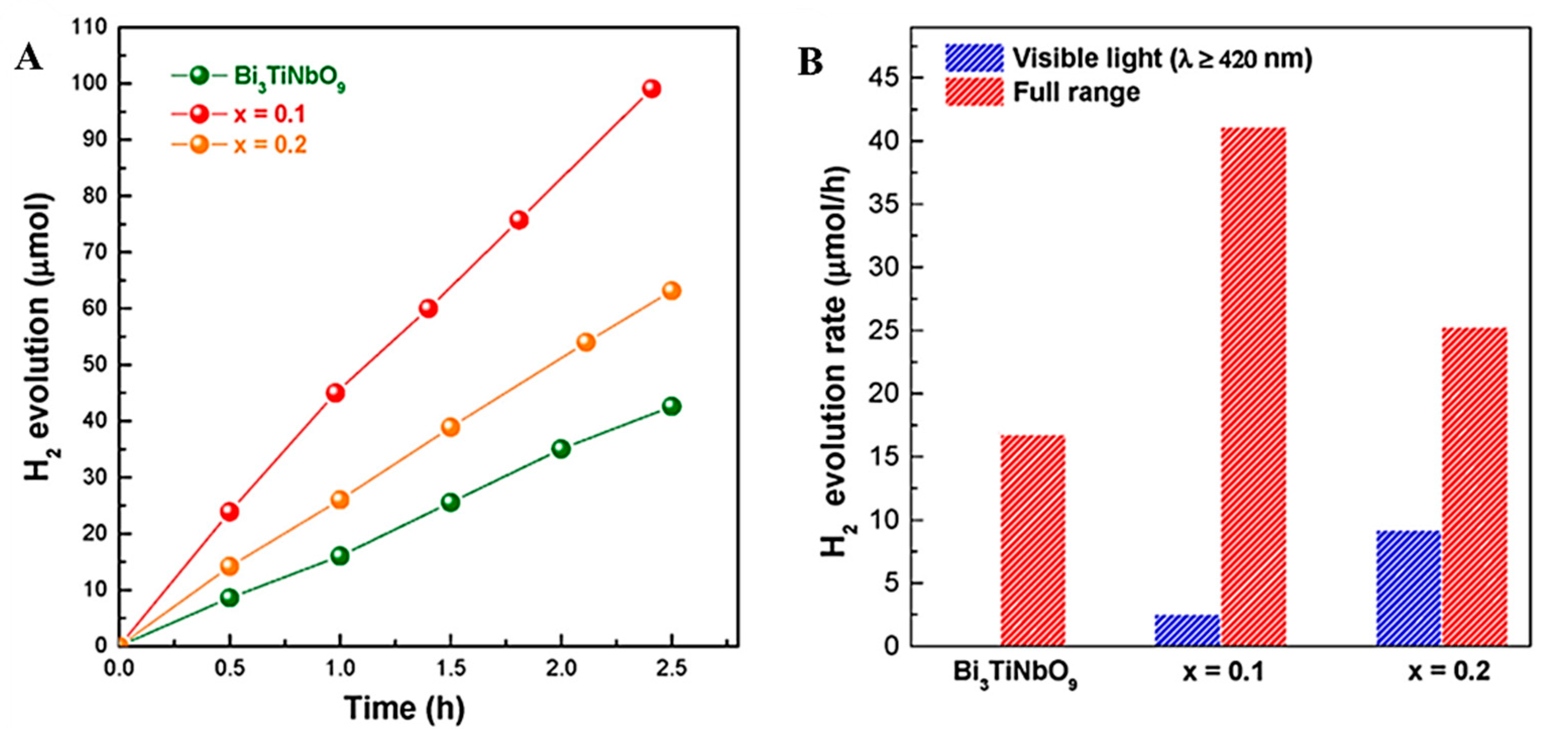
| Influencing Factors | Effect on Photocatalysis | |
|---|---|---|
| Catalyst concentration | - The reaction rate increases with the increase of the catalyst concentration. | |
| - Above a certain dose, the reaction rate decreases as the catalyst concentration increases. | ||
| Light source and light intensity | Light source | - Provide light of different wavelengths. |
| Light | - Improve light intensity and promote photocatalytic | |
| intensity | reaction. | |
| PH value | - Related to target degradation products. | |
| Plus oxidants | - Reducing the recombination of photogenerated electrons and holes to improve photocatalytic efficiency. | |
| Inorganic ion | Anion | - Improve the separation speed of photogenerated electrons and holes and promote photocatalytic reaction. |
| Cation | - Becomes a scavenger of hydroxyl radicals, forming anion radicals. | |
| - The competitive adsorption of active sites on the surface of the catalyst may affect the photocatalytic degradation of organics. | ||
| Temperature | - Has little effect. |
| Semiconductor | Crystal Structure | Band Gap Structure (PH = 7) | Reference | ||
|---|---|---|---|---|---|
| CB | VB | Eg/eV | |||
| TiO2 | Anatase | −0.50 | 2.70 | 3.20 | [149] |
| ZnO | −0.31 | 2.89 | 3.20 | [150] | |
| CuO | −1.16 | 0.85 | 2.00 | [151] | |
| CdS | −0.90 | 1.50 | 2.40 | [152] | |
| ZnS | −1.04 | 2.56 | 3.60 | [101] | |
| g-C3N4 | −1.30 | 1.40 | 2.70 | [139,153] | |
| g-C3N4 | −1.53 | 1.16 | 2.70 | [154] a | |
| Ta3N5 | −0.75 | 1.35 | 2.10 | [155] | |
| TaON | −0.75 | 1.75 | 2.50 | [156] | |
| Fe2O3 | 0.28 | 2.48 | 2.20 | [157] | |
| Bi2O3 | 0.33 | 3.13 | 2.80 | [158] | |
| BiVO4 | −0.30 | 2.10 | 2.40 | [159] | |
| WO3 | −0.10 | 2.70 | 2.80 | [160] | |
| Ag3PO4 | Cubic | 0.04 | 2.49 | 2.45 | [161] |
| Modification Method | Advantage | Disadvantage |
|---|---|---|
| Particle doping | - Reduce bandgap | - Introduce defects |
| - Reduce particle size | ||
| Precious metal depositing | - Enhance electron-hole separation | - Expensive |
| Surface dye photosensitization | - Broaden the light response range | - Expensive |
| - Dyes may be photolyzed | ||
| Semiconductor compound | - Reducing the complex of electron-hole pairs | - Energy loss |
| - Broaden the light response range |
© 2019 by the authors. Licensee MDPI, Basel, Switzerland. This article is an open access article distributed under the terms and conditions of the Creative Commons Attribution (CC BY) license (http://creativecommons.org/licenses/by/4.0/).
Share and Cite
Zhang, F.; Wang, X.; Liu, H.; Liu, C.; Wan, Y.; Long, Y.; Cai, Z. Recent Advances and Applications of Semiconductor Photocatalytic Technology. Appl. Sci. 2019, 9, 2489. https://doi.org/10.3390/app9122489
Zhang F, Wang X, Liu H, Liu C, Wan Y, Long Y, Cai Z. Recent Advances and Applications of Semiconductor Photocatalytic Technology. Applied Sciences. 2019; 9(12):2489. https://doi.org/10.3390/app9122489
Chicago/Turabian StyleZhang, Fubao, Xianming Wang, Haonan Liu, Chunli Liu, Yong Wan, Yunze Long, and Zhongyu Cai. 2019. "Recent Advances and Applications of Semiconductor Photocatalytic Technology" Applied Sciences 9, no. 12: 2489. https://doi.org/10.3390/app9122489
APA StyleZhang, F., Wang, X., Liu, H., Liu, C., Wan, Y., Long, Y., & Cai, Z. (2019). Recent Advances and Applications of Semiconductor Photocatalytic Technology. Applied Sciences, 9(12), 2489. https://doi.org/10.3390/app9122489