1. Introduction
Industry 4.0 is seen as “the integration of complex physical machinery and devices with networked sensors and software, used to predict, control, and plan for better business and societal outcomes” [
1]. The network capabilities are identified as some of the defining characteristics of Cyber Physical Production Systems (CPPS), which are at the core of Industry 4.0 [
2]. In this scenario, new network technologies are required to connect more devices, such as sensors, actuators, and autonomous systems in industrial applications. Some technologies such as industrial wireless networks (IWNs) or Industrial Internet of Things (IIoT) are expected to act as key enablers at smart factories and intelligent manufacturing systems [
3,
4]. In particular, IWNs have great potential for monitoring and control tasks in factory automation, since they might introduce benefits such as—(1) flexibility to easily modify the layout of the links; (2) connection between monitoring or decision nodes and mobile devices or parts; and (3) reducing, or even eliminating cabling, which might be expensive and cumbersome. Thus, the introduction of wireless networks in the industry is expected to improve the productivity and efficiency of the processes [
5].
Unfortunately, the nature of wireless communications introduces known issues, such as fading, multipath propagation, shadowing, and interferences, which increase the bit error rate and make them unpredictable [
6]. For this reason, introduction of these technologies in factories face several challenges, such as—(1) reducing the interferences (caused either by other networks, the industrial processes or the environment); (2) avoiding congestions to achieve the demanded Quality of Service (QoS) of applications; and (3) adequately manage the frequency spectrum, which is especially complex in large factories [
5]. In addition, wireless nodes are frequently fed with batteries, which provide energy for a limited period of time. During the last years, there have been considerable advances in wireless technologies but these technologies are still far from being mature, especially in critical applications. In [
7] some indicators of their scarce maturity were identified such as weak security, lack of a dedicated spectrum, lack of a dedicated physical layer, overpromised performance, and poor scalability. Despite these challenges, wireless technologies are considered to be at a critical point for deployment in industrial applications since the benefits that they introduce might overcome the disadvantages. For this reason, more research is needed in order to find out whether the benefits of using wireless technologies—in certain layouts—overcome the drawbacks, to understand in which applications they might be introduced, as well as the best practices, especially in critical applications like those that involve control operations over wireless networks [
3,
5].
Wireless technologies are already accepted in non-critical industrial applications, i.e., those in which a communication failure does not cause severe concerns (for humans) or large economic losses [
7]. The appropriateness of IWNs in different types of applications have been discussed in [
5]; essentially, they are regarded as safe for factory and building monitoring, condition alarming, and supervisory control. For other operations, such as feedback control and safety operations, they are still often discarded, since they are not considered to provide sufficient reliability, integrity, and security, when compared to wired technologies. Some authors assume that wireless technologies might not be adequate for some operations and propose the use of hybrid approaches, i.e., combining both wired and wireless technologies in order to improve the overall flexibility, efficiency, and performance of the control systems [
8], or using IWNs at control applications with wired backups. IWNs are now starting to be considered for critical operations. Although factory automation tends to be quite conservative, the potential benefits of the introduction of IWN, on the one hand, and the arrival of the Industry 4.0 paradigm on the other, are promoting the adoption of wireless technologies in industrial environments.
There are several wireless technologies available for factory automation applications. The majority of them work at the Industrial Scientific and Medical (ISM) radio bands, in particular at the 2.4 GHz. They are typically based on the IEEE 802.15.1 and IEEE 802.15.4 standards, Bluetooth and Zigbee being the most popular technologies. A deep discussion of several technologies aimed at factory automation is presented in [
9]. Some of the analyzed solutions, e.g., WirelessHART or ISA SP100.11a are built upon the IEEE 802.15.4 2.4 GHz physical layer, with some modifications at the MAC layer. Other technologies, like WISA, are built upon the physical layer of the IEEE 802.15.1 standard. Even though some of these technologies introduce mechanisms to improve coexistence, they contend in the medium and, consequently, are vulnerable to transmissions carried out by non-coordinated nodes. After all, most existing industrial wireless solutions are built on general-purpose chips and standards. Some brand new technologies, known as Wireless High-Performance (Wireless HP) [
10], have also emerged. They aim to provide high performance in data rate, reliability, and latency. Although they are expected to play an important role in the future, they are still in an incipient stage.
Designing a Wireless Networked Control System (WNCS) is a complex task and must be approached in a holistic way. WNCS require a specific QoS, in order to be usable but wireless technologies are intrinsically unpredictable. Therefore, both the communications QoS and the control algorithm are intertwined, as discussed in [
11,
12,
13], for example, finding the optimal sampling period that does not disturb the control algorithm or deciding how the control algorithm faces message delays and jitter, as well as the message dropouts. In addition, the power consumption at the wireless nodes must be considered, especially in mobile or difficult to access nodes, since they are typically powered with batteries.
This work focuses on several issues that must be considered for designing and implementing wireless control schemes, including selecting an adequate sampling period, integrating the communication technology with the sensors and controllers, designing the format of the frames, identifying loss/corrupted packages, establishing the error recovery mechanisms, evaluating the delay, and so on. This article assesses the use of wireless technologies to be introduced in industrial control applications, namely in control applications embedded in big machinery (up to 5 m). In particular, the control applications are built with XBee and LabVIEW. On one hand, XBee is used for providing wireless communications among sensors, controllers, and actuators. XBee devices are based on the IEEE 802.15.4 protocol, which is known for its low power consumption. Other technologies—especially Bluetooth Low Energy (BLE)—were also considered for this work, but the authors selected XBee since this is more mature for low consumption devices, allows more complex topologies that provide higher flexibility, and allows the use of different operating frequencies (868 MHz, 900 MHz and 2.4 GHz). This might become an important issue when building control systems in which some components, mainly sensors, are powered with batteries. On the other hand, LabVIEW is used to implement the controller that gets the information from the wireless sensors, processes the control algorithm, and sends the control signal to the wireless actuators. LabVIEW allows the implementation of complex control algorithms by combining the available modules. In addition, LabVIEW works well at different sampling periods, provides several alternatives for communication purposes and utilities for saving monitored information. Several experiments were carried out to compare wireless communication with wired ones. In particular, the offset and message dropout were analyzed at different distances and sampling periods, and the message delay was measured. Additionally, the influence of Wi-Fi interferences was checked. Finally, as a matter of example, wireless technologies were used for the remote control of a high-precision positioning tool, by means of piezoelectric actuators.
The layout of this paper is as follows.
Section 2 analyzes some related studies on the field of XBee used in monitoring and control systems.
Section 3 describes the control layout, topology, and design of the frames.
Section 4 discusses some tests carried out to validate the layout and technologies used in this work.
Section 5 describes the application of the proposed layout for implementing a high precision position control application in which communications are implemented with XBee. Finally,
Section 6 draws some conclusions.
2. Related Work
Several standards are used in process-automation applications, ZigBee being one of the most popular for monitoring applications [
9,
14]. This technology provides good support when compared with the Wi-Fi, Bluetooth, and Ultra Wide Band (UWB) standards of the transmission range [
15]. In particular, ZigBee networks present some advantages in terms of energy consumption and flexibility, especially in large networks [
14]. In ZigBee networks, there should just be one Coordinator node per network that is the controller of the whole network, which is irresponsible for choosing the network channel and organizing it. Since there might be several routes in a ZigBee network, other nodes, Routers, are responsible for maintaining the infrastructure of the ZigBee network. These nodes do not gather data or start the message transmission but only transmit data from router to router, or from the end devices to the coordinator. Finally, end-devices do not route. They are responsible for gathering data and delivering it to the nearby router or coordinator. All ZigBee nodes are designed to be of small size, light weight, and low power consumption. The technology allows the connection of up to 65,535 nodes. ZigBee is suitable for use in monitoring and control applications, such as remote healthcare, industrial control, fire detection, environmental monitoring, and so on [
16]. In this work, XBee modules were used. These modules support both the original ZigBee network as well as a vendor proprietary network, known as DigiMesh. In [
14], several experiments under different environments have been designed to evaluate the performance of both networks.
Sometimes different technologies must coexist while using the same bandwidth spectrum, creating severe interference problems. This is the case for ZigBee and Wi-Fi networks, since they typically work at the 2.4 GHz ISM band. Some approaches have been analyzed, in order to alleviate this issue, aimed at achieving a more robust communication [
17,
18]. The incipient IEEE 802.15.4e standard proposes a Medium Access Control (MAC) layer that supports collision-free wireless channel access mechanisms for industrial, commercial, and healthcare applications [
19].
ZigBee technology is mostly used for monitoring applications. Nowadays, some monitoring applications have been built over ZigBee, as a result of the introduction of smart grids. In [
20], the feasibility of sending messages from intelligent electronic meters to concessionaires, through a ZigBee network, was analyzed. In [
21], the networked control of a photovoltaic based AC Microgrid was presented. In this work, both CAN and ZigBee were considered. In [
22], ZigBee modules were used for the energy management, efficiency optimization, and metering services, within a smart grid.
Other applications involved the control of robots or machinery. For example, in [
23] the remote monitoring and controlling of robotic arms by means of ZigBee technology was discussed. In [
24], a model to control a robotic vehicle by means of using hand gestures with an accelerometer was introduced. In [
25], a model predicting a control flocking algorithm aimed at controlling a multi-drone system was presented. In [
26], a network-based discrete proportional integral (PI) control aimed at controlling a continuous time linear system was designed. There have also been some works in the field of Industrial IoT. For example, in [
27] a monitoring architecture for process automation technologies with low impact on the sensor nodes aimed at industrial set ups was proposed.
3. Description of the Control Layout
In this work, star-topology was considered for the WNCS. The controller, implemented at the central device, received the data from the distributed sensors, executed the control algorithm, and sent the reference to the distributed actuators, in order to control the plant. The controller device was implemented with a powerful platform, namely a NI myRIO device. This was a real-time embedded computer with FPGA capabilities, which was able to execute complex control algorithms by means of the LabVIEW software. The NI myRIO used a dual-core ARM Cortex-A9 processor and ran the NI Linux Real-Time OS. The CompactRIO architecture (also manufactured by National Instruments), followed the same philosophy but it was based on a set of modules. Thus, it might have better adapted to complex systems, given that it offered scalable computing power and different input and output modules. In addition, both the NI myRIO and the CompactRIO architecture allowed the implementation of easy hybrid control systems, i.e., those in which remote devices are connected by means of both wired and wireless links. For the wireless communication with sensors and actuators, the XBee technology was chosen. National Instruments and several other companies designed the NI VISA protocol, aimed at easing the communication with different devices. In particular, the NI VISA protocol allowed the connection between the XBee antenna located at the control computer and the LabVIEW application that executed the control algorithm.
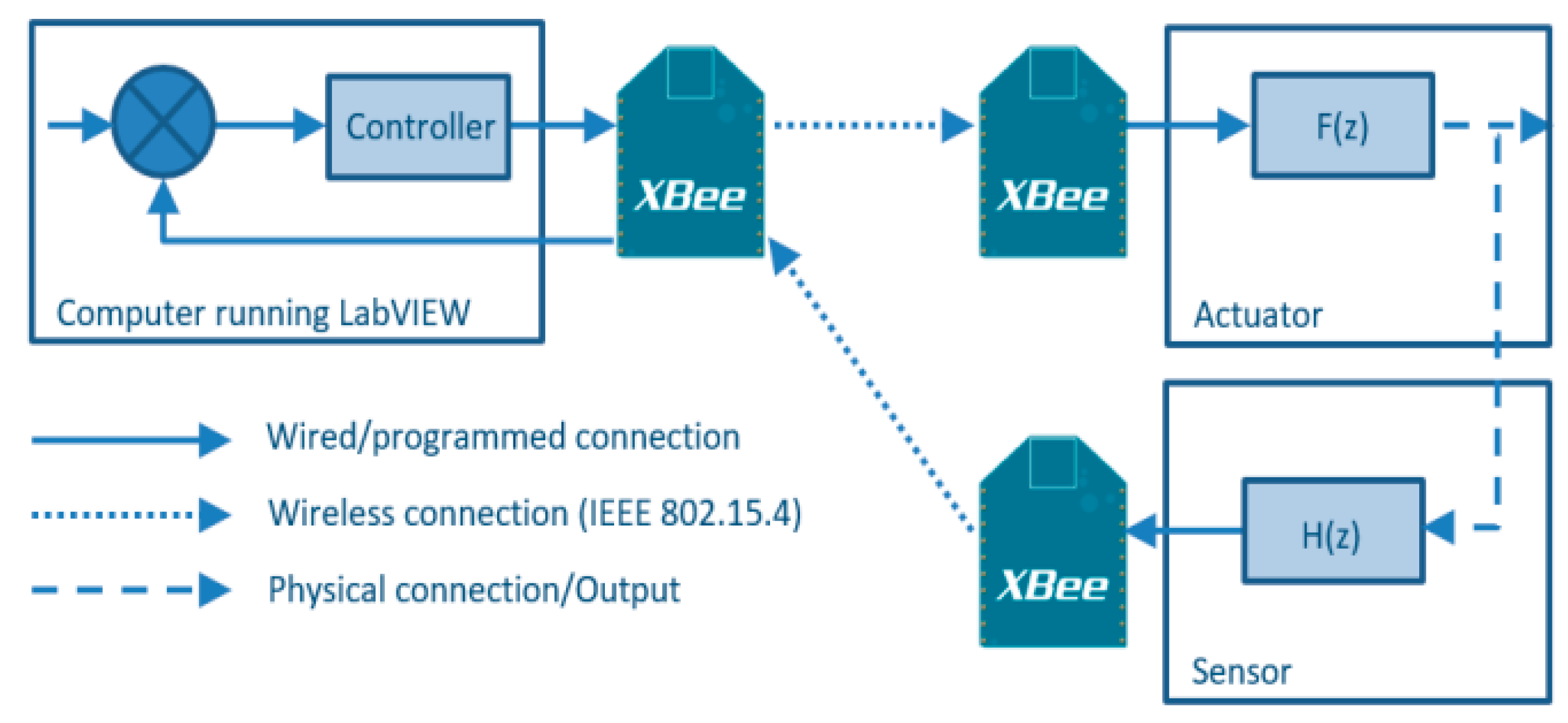
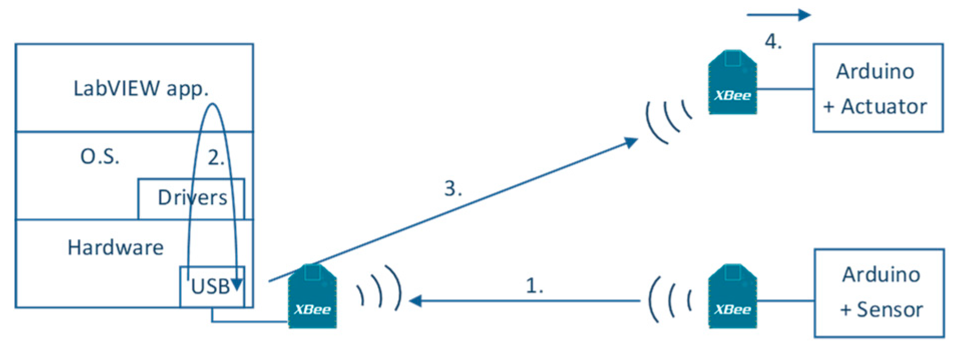
In this work, the authors aimed at carefully analyzing the behavior of control applications that followed the layout shown in
Figure 1. For this purpose, the authors analyzed a basic single input single output (SISO) closed loop control application with (1) one sensor, (2) the control algorithm (executed at the computer), and (3) one actuator. Both the communications and the control algorithm were especially intertwined in the design of WNCS, consequently, the introduction of more sensors and actuators should be adequately scheduled, in order to manage the communication bandwidth and reduce the impact of collisions on the QoS performance. One possible approach would be the introduction of time-triggered approaches. Several TDMA scheduling algorithms for the wireless sensor networks have been discussed in [
28].
Figure 1 shows the sensor connected to the physical system, connected to an XBee module like the XBee End Device. The use of a microcontroller allowed the execution of any pre-processing algorithm for the acquired value of the sensor (represented as H(z) in
Figure 1). The measured values were serialized and sent to the NI myRIO device (which ran the control algorithm in LabVIEW). The computer was connected to the XBee module, configured as the XBee Coordinator, by means of a USB link. The LabVIEW VISA device has proven to be the simplest alternative to manage the data received/sent by the XBee module. The control algorithm generated the signal to be serialized and sent to the actuator, configured as an XBee End Device. Again, the use of a microcontroller on the actuator’s side might be necessary for executing F(z).
XBee modules could be programmed in two modes—the AT mode and the API. The latest provided a higher flexibility, since it allowed a formatting of the frames, to better adapt to the applications. However, it required a lower programming level, since the programs must dig into the frames to get the information. Regardless, this was considered the best approach for this kind of applications and, consequently, it was used at the sensor, controller, and actuator, to define the application protocol over XBee. Afterwards, the format of the API frames was briefly described. API frames were divided into four sections—(1) start delimiter, all frames started with the same byte, 0x7E; (2) length of the frame—the next two bytes; (3) API-specific Structure—which followed the structure of the application protocol used, and could contain as many bytes as designed; and (4) checksum—which was the calculated checksum of the bytes in the API-specific structure.
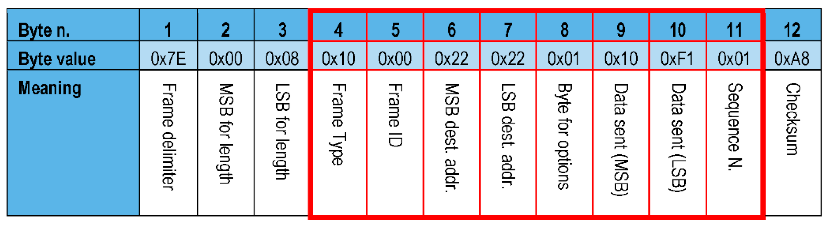
As a matter of example for the sake of describing the structure of the frames,
Figure 2 shows a typical frame. The whole size of the frame was 12 Bytes. The API-specific structure, represented by red lines, defines the application protocol for sending/receiving the values to/from the sensors or actuators. This frame has been specifically designed for control applications similar to the one presented in this work. In the example frame shown in
Figure 2, the API-specific structure included the following bytes—(Byte 4) frame type, in which 0x10 meant that the frame was a Zigbee Transmit Request; (5) frame ID was 0x00, which disabled the response frames; (6–7) 16 bits for the destination address—in this case 0x2222—divided into its MSB and LSB; (8) byte for options, in this case 0x01, which disabled the retries; (9–10) 16 bits for the data sent and the reading of a sensor (in the example the 0x10F1 value was sent); and (11) sequence number, which was used to detect whether all frames were delivered (in the example this was 0x01), since this was the first frame sent. Finally, in byte 12 the checksum of the message was included. This information was used for detecting whether the received message was corrupted. In such a case, the message was discarded.
In order to connect any device (sensor or actuator), the precision of the ADC (Analog-to-Digital Converter) at the XBee module was analyzed. The results have been presented in the next section.
4. Experimental Tests
In order to evaluate whether XBee technology was suitable for control applications, several experiments at different sampling periods and distances were designed to compare wireless and wired communications. First, the Analog-to-Digital Converter (ADC) included in the XBee device was compared with a National Instruments myDAQ USB-6008 board and an Arduino Uno board. Second, the offset and message dropout were analyzed for different distances and sampling periods. Third, the message delay was analyzed at different distances and sample periods. Finally, the influence of Wi-Fi interferences in the XBee transmission was checked. This evaluation aimed to shed some light into the application of this technology in control applications.
The test set up was aimed at analyzing the performance of wireless communications in control applications. The experimental layout for a Single Input Single Output (SISO) Control System with one sensor actuator and controller has been reproduced in
Figure 1. The NI VISA device was used to establish the communication between the XBee and the LabVIEW application. Just for evaluation purposes, one potentiometer was used as the generic analog sensor and one small DC motor was used a generic actuator. The sensor module, implemented by means of an Arduino board, sampled the values of the sensor and sent them to the XBee antenna. For the actuator, an Arduino was also connected to a XBee module (by means of an Arduino XBee shield). This module received the control signal generated by the LabVIEW control algorithm. The DC motor was connected to one of the PWM Arduino board pins. The XBee frames followed the format defined in the previous section. In parallel to the wireless communication, a NI myDAQ USB-6008 acquisition board was used to compare wireless and wired communications. This was a low cost board designed by National Instruments and, consequently, had very good compatibility with LabVIEW, by means of ad hoc libraries and drivers. The NI myDAQ USB-6008 also provided higher resolution (12 bits), when compared to the XBee and Arduino ADCs (10 bits). Due to its higher resolution and lower bit error rate, it was considered to be the reference value for the tests carried out. The following subsections describe these experiments and briefly discusses the results.
4.1. Comparing Different ADCs for XBee Modules
This test was aimed at designing the interface between sensors and XBee modules. In particular, this subsection analyzed the influence of the ADC in the process of digitalizing the sensor measures. For this purpose, three different ADCs were compared—(1) the ADC included at the XBee module; (2) an Arduino Uno connected in series to an XBee module; and (3) a specific acquisition board, namely the NI myDAQ USB-6008, wired to the computer by means of a USB link. With regards to the resolution, the XBee ADC represented the measured analog voltage into a 10-bit value (same as that of Arduino Uno), and finally, the NI myDAQ USB-6008, which had a higher resolution was taken as the reference value. The values measured from the three were compared and transmitted to a computer using LabVIEW. These tests were done at a distance of 0.5 m, using a sample period of 100 milliseconds.
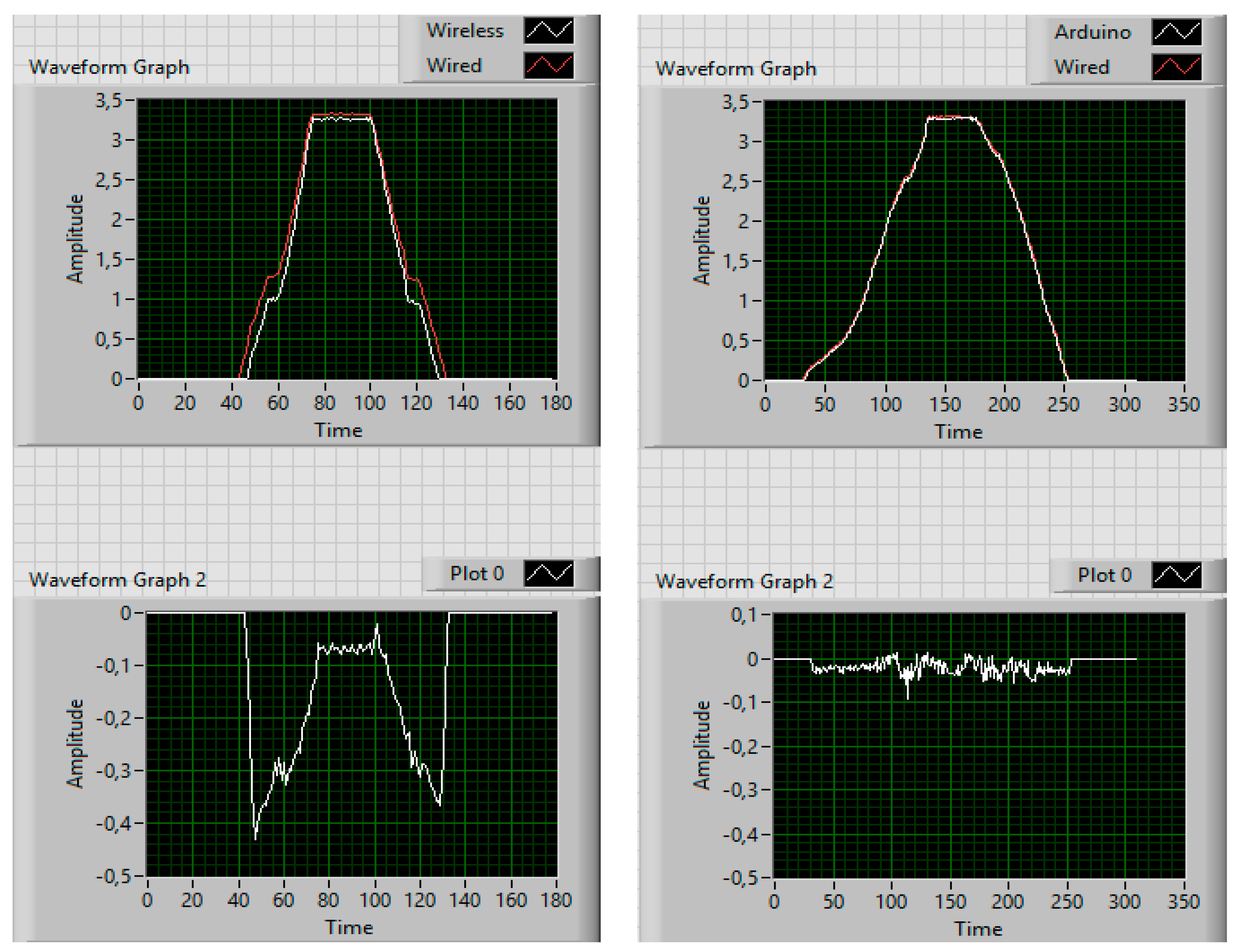
The comparison between the XBee ADC and the NI myDAQ proved that the behavior of the XBee ADC was quite limited at low voltages. In particular, it was shown that the XBee ADC introduced an offset of around 0.4 Volts when 0 volts were measured. The higher the voltage, the lower the difference between the values obtained from the XBee ADC and the NI myDAQ. Due to these poor results, the authors introduced an Arduino Uno in order to digitalize the signal of the sensor. These values were compared with those acquired by the myDAQ board. In
Figure 3 (left panel), the wireless signal obtained from the ADC at the XBee is compared with the wired signal, measured by the myDAQ. The difference could reach up to 0.4 volts.
Figure 3 (right panel) compared the wireless signal (measured by the Arduino Uno connected to the XBee module) with the wired signal received from the myDAQ. It could be noticed that, in this case, the difference between both signals was considerably smaller. For this reason, the authors connected the sensor using an Arduino Uno and an XBee module.
4.2. Comparing Offset and Message Dropout at Different Distances
The second experiment was aimed at investigating the influence of—(1) the sample period and (2) the distance between the computer and the sensor/actuator, in wireless connections. In particular, the dropout rate and the difference between the wired and the wireless measured values were analyzed. In this test an Arduino Uno was connected in series to an XBee module, so that the Arduino Uno acquired the value from the sensor, serialized it to the XBee module, which then sent it to the LabVIEW application.
For this purpose, several experiments were carried out in which both characteristics (sample period and distance) were modified. More specifically, sample periods of 30, 50, and 100 milliseconds were considered. Regarding distance, since this work was aimed at evaluating the introduction of XBee modules in machinery of up to 5 m, the distances ranged from 0 (very short distance), 0.5, 2, and 5 m. The tests consisted of periodically sending sensor values at different frequencies (namely, 30, 50, and 100 milliseconds) and varying the distance between computer and nodes, at either 0 m (very close), 0.5 m, 2m, and up to 5 m. The duration of the test was always 30 s. The following data were analyzed for this test: (1) the message dropout rate, which was obtained from the frame checksum failures, as well as bad sequence numbers, see
Figure 2; (2) the average difference between the wired and wireless values received for every value of frequency and distance; and (3) the standard deviation of the difference between the wired and wireless signals.
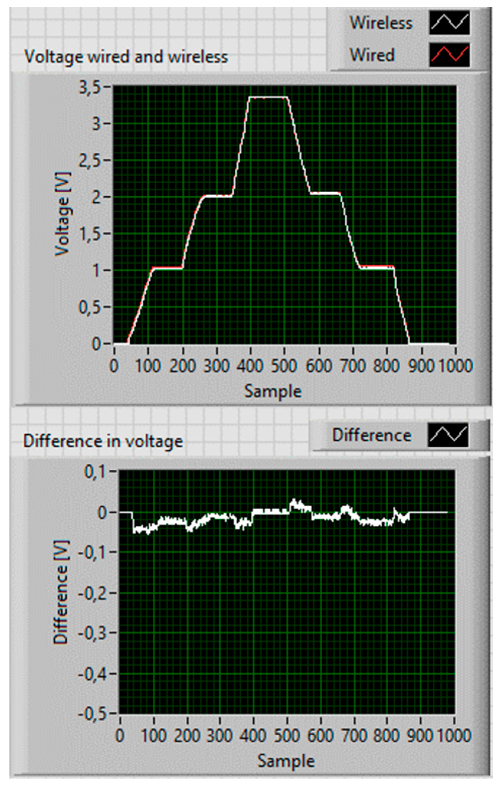
Table 1 summarizes the results obtained from the tests carried out. For example,
Figure 4 shows the test for a sampling rate of 30 milliseconds, at a distance of 0.5 m. The duration of the test was 30 s.
The first thing to notice in
Table 1 is that the message dropout measured averages below 2%. Additionally, no correlation was found between message dropout and distance (at least for the considered distances) and the sampling periods. The authors assumed that the high values at the standard deviation were mostly due to the effect of spurious interferences during the tests, as they were performed in a University Laboratory that experienced intensive Wi-Fi traffic (in a subsequent subsection, the effect of Wi-Fi interferences is confirmed). The most remarkable outliers occurred at five meters, where the effect of the interferences was expected to be more noticeable.
4.3. Message Delay
The third experiment was aimed at measuring the full message delay between sending a signal from the sensor to the computer and its reception at the actuator (see
Figure 5). The time difference between sending and receiving was measured using an oscilloscope. These tests were also carried out at several distances—0 m (very close), 0.5 m, 2 m, and up to 5 m. In order to compare the message delay, a wired connection was also used as a reference.
The message delay was measured ten times for the distances specified above.
Table 2 presents the mean and standard deviation for the message delay at several distances. Note that the message delay measured was a two-way delay which involved all steps shown in
Figure 5.
Two conclusions could be drawn from this experiment—(1) the distance had a reduced impact on the delay (at least up to 5 m), and (2) the delay was significantly lower in the wired connection, as expected. For this experiment, the XBee modules were configured to transmit the data at a baud-rate of 9600 bits per second. Considering that the frames were around 100 bits, every connection at 9600 bps took around 10 ms. There were several serial connections to close the loop (see
Figure 5)—(1) from the sensor XBee to the XBee at the NI myRIO; (2) from the XBee to the LabVIEW application and back to the XBee; (3) from the XBee at the NI myRIO to the actuator XBee; and (4) from the actuator XBee to the Arduino Uno. This could be explained by the mean time (which was around 46 milliseconds) and a higher standard deviation, since there were several stages involved. To reduce the time needed to translate the data into a frame, a higher baud-rate could be used. A second test was done at three different baud-rates at a very short distance. The obtained results are shown in
Table 3.
The table shows the influence of the communication speed configuration (in bits per second) at the delay. For example, at a baud-rate of 38,400, the time to send one frame would be considerably shorter and it would have a big impact on the closed loop communication. However, the authors expected a higher dropout rate. If the time used by the computer to process the data was considered to be the same for all tests (regardless of the communication speed), the following four stages were involved:
The communication between the XBee module at the sensor and the XBee module at the control computer. The frames considered had a 100 bits size.
At the control computer, the message was received and passed to the application. As shown in
Figure 5, the influence of several components could introduce jitter.
The generated frame was serialized and immediately transmitted by the XBee.
After the entire frame was received by the actuator XBee, the reference was extracted from the frame and sent to the Arduino.
4.4. Interferences with Wi-Fi
The influence of Wi-Fi interferences over ZigBee is well-known, since both technologies work at the radio band of 2.4 GHz. Several works, such as [
29,
30], provide a detailed analysis about this topic. In particular, in [
30] it has been shown that ZigBee might be severely interfered by Wi-Fi, and they proposed a theoretical model that explained the phenomenon. In [
30], a safe distance of 8 m between both technologies, has been recommended, to reduce interferences.
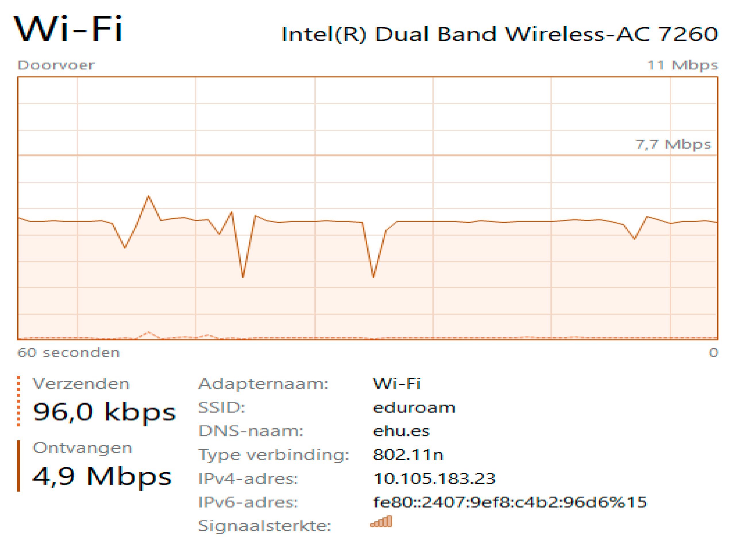
In the present work, we were devoted to simply confirming the influence of interferences in communication. For this reason, the tests were carried out in a clearly unfavorable scenario, to experimentally measure the ill effects of the interferences between both technologies. The proposed test consisted on setting the two antennas (ZigBee and Wi-Fi) close to each other, at a distance of 30 cm, and analyzing the experimental results. In addition, large files were downloaded on the computer executing the application, while the XBee application was working. The results were analyzed to check whether the dropout increased due to the interference.
A high-resolution video was downloaded by means of the 802.11n interface, while at the same time, the controller was acquiring data from the sensor by means of XBee. The authors experimentally measured the download Wi-Fi speed at the computer which, on average, was of 4.9 Mbps (see
Figure 6). During this test, the message dropouts were checked and saved in one file for off-line analysis.
The authors analyzed the behavior of the XBee communication at the Wi-Fi speed peaks and observed that at the peaks, up to the 60% of the messages were not received by the XBee on the computer (note that this test was clearly very unfavorable, since the authors maximized all the drawbacks, short distance, high traffic, etc.). This value went far beyond the dropout data obtained in Test 2. Obviously, this significant dropout was caused by interferences, since both XBee and Wi-Fi work at 2.4 GHz.
Interferences caused by Wi-Fi at 2.4 GHz could be avoided by either using the XBee modules in a Wi-Fi free zone or using the XBee modules that operate in a different frequency (some XBee devices work at 868 MHz or 900 MHz).
4.5. Discussion
This section analyzes the use of XBee wireless technology for control applications programmed with LabVIEW. A Single Input Single Output (SISO) system was considered, in which both the sensor and actuator were connected wirelessly, by means of XBee modules. Several experimental tests were carried out in order to explore the use of these technologies. Namely, the experiments carried out involved analyzing—(1) the performance of the Analog-to-Digital Converter (ADC) included at the XBee device; (2) the offset and message dropout for different distances and sampling periods; (3) the message delay at different distances and sample periods; and (4) the presence of Wi-Fi interferences in a very unfavorable scenario. The results of these tests should show if the combination of XBee and LabVIEW was adequate to building some non-critical WNCS
The first conclusion drawn from these experiments was that the dropout rate was not so high, for the measured distances (up to 5 m) and sampling periods (up to 30 ms). For the tests carried out, the dropout was always around 2%. During the tests, it was also proven that the flexibility of using XBee antennae was very high, since wireless technologies allow to easily move the devices, at different distances.
Nonetheless, there were also weak points. A higher delay was created. This delay was very sensitive to the baud-rate of the XBee configuration. However, the authors believe that a higher speed could increase the dropout. Additionally, it was confirmed that Wi-Fi might cause serious problems of interference with XBee, since both were using the 2.4 GHz band. For this reason, the authors evaluated the use of XBee modules that work at different frequency bands, such as 868 MHz or 900 MHz. Another finding was that the ADC used by the XBee module did not provide good results. It was improved by connecting an Arduino Uno board for sampling the signal. However, for some high precision applications, this approach could still be poor. For these cases, more precise technologies should be analyzed.
In general, it could be concluded that for non-critical systems or for monitoring purposes only, the analyzed combination could have become a viable alternative, even though it had some limitations. However, for more critical applications several factors must be improved, either by more precisely tuning the XBee configuration and, if possible, reducing the environmental interferences.
5. Case Study
This section analyzed the performance of the XBee communications in a particular control application. Namely, a high precision positioning application, based on a piezoelectric actuator. Piezoelectric actuators (PEAs) are widely used in a variety of applications where ultrahigh precision is required [
31]. They are frequently introduced at micro-positioning applications, due to their high resolution (in the range of nanometers), large blocking force (hundreds of N), high stiffness, large bandwidth, and fast response. Unfortunately, the biggest problem of piezo-driven stages comes from the nonlinearities in the PEA, attributed to hysteresis, creep, and drift. These problems could be addressed by selecting appropriate controllers aimed at compensating these effects [
32]. In this work, the authors focused on evaluating the performance of wireless communications (based on XBee technology) for avoiding the wiring between the controller, executed in a NI myRIO computing platform, and a commercial PEA. Since the purpose of this work was to test wireless communications in control applications, a well-established control algorithm was implemented at the NI myRIO, namely a proportional-integral (PI) controller. However, the authors were aware that the performance of this controller could be improved [
32]. The presented tests are aimed at evaluating the performance of XBee communications in wireless control networked applications.
5.1. Materials and Layout
The plant used in these experiments was a PEA, namely a PK4FYC2, supplied by Thorlabs, which provided a 38.5 µm range. Since a PEA is a high precision, non-linear actuator, the authors decided to use the auxiliary modules provided by the vendor. The PEA was actuated with a 0–150 V voltage by means of an open-loop piezo driver (Thorlabs Ref. KPZ101), which converted the input range of the driver (0–10 V) into the actuator range (0–150 V). For close-loop applications, a pre-amplification circuit was needed, for this purpose the Thorlabs Ref. AMP002 pre-amp circuit was also used. Due to the short range of the actuator (0–38.5 µm), the displacement was measured by means of a high precision strain gauge integrated on the PEA. Thus, the position of the actuator was measured by means of a strain gauge reader (Thorlabs Ref. KSG101) that accurately delivered the position.
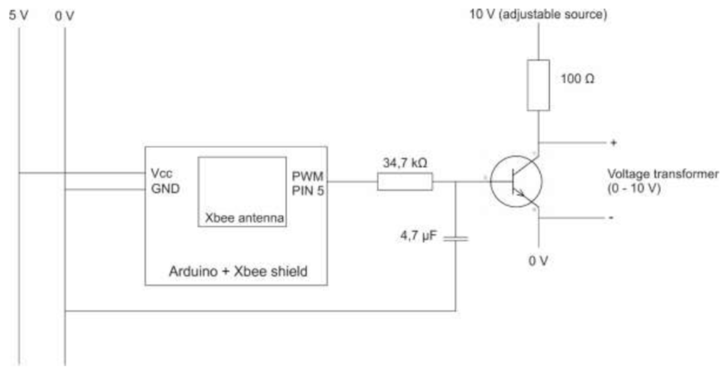
XBee communication was used to connect the PEA actuator with the controller. More precisely, an XBee module was connected to an Arduino Uno, which was used both for reading the position of the PEA and setting the position reference of the piezo driver. The communication between the control algorithm, executed in a NI myRIO device, and the Arduino Uno was established by means of the XBee technology. Thus, the control algorithm was executed wirelessly. Since the piezo driver KPZ101 must be fed with a 0–10 V control signal an ad hoc module was used for testing purposes. This module was aimed at amplifying the output signal of the Arduino, received from the XBee module, in order to deliver the control signal to the piezo driver (See
Figure 7). Thus, the module was composed of—(1) an XBee module, for communication purposes; (2) an Arduino Uno, for reading the position of the PEA from the KSG101 and setting the reference signal for the PEA; (3) an ad hoc amplifying module that converted the PWM output signal from the Arduino Uno into an analog signal to feed the piezo driver KPZ101. This amplifying circuit, based on a general purpose BJT NPN 2N2222A transistor (see
Figure 7), allowed the feeding of the PEA pre-amplifier within the range of 0 and 10 V, so the same approach was applicable for other devices. Thus, this module sampled the position of the PEA and sent it, by means of the XBee module, to the NI myRIO, where the control algorithm was executed, and finally received the control signal for positioning the actuator.
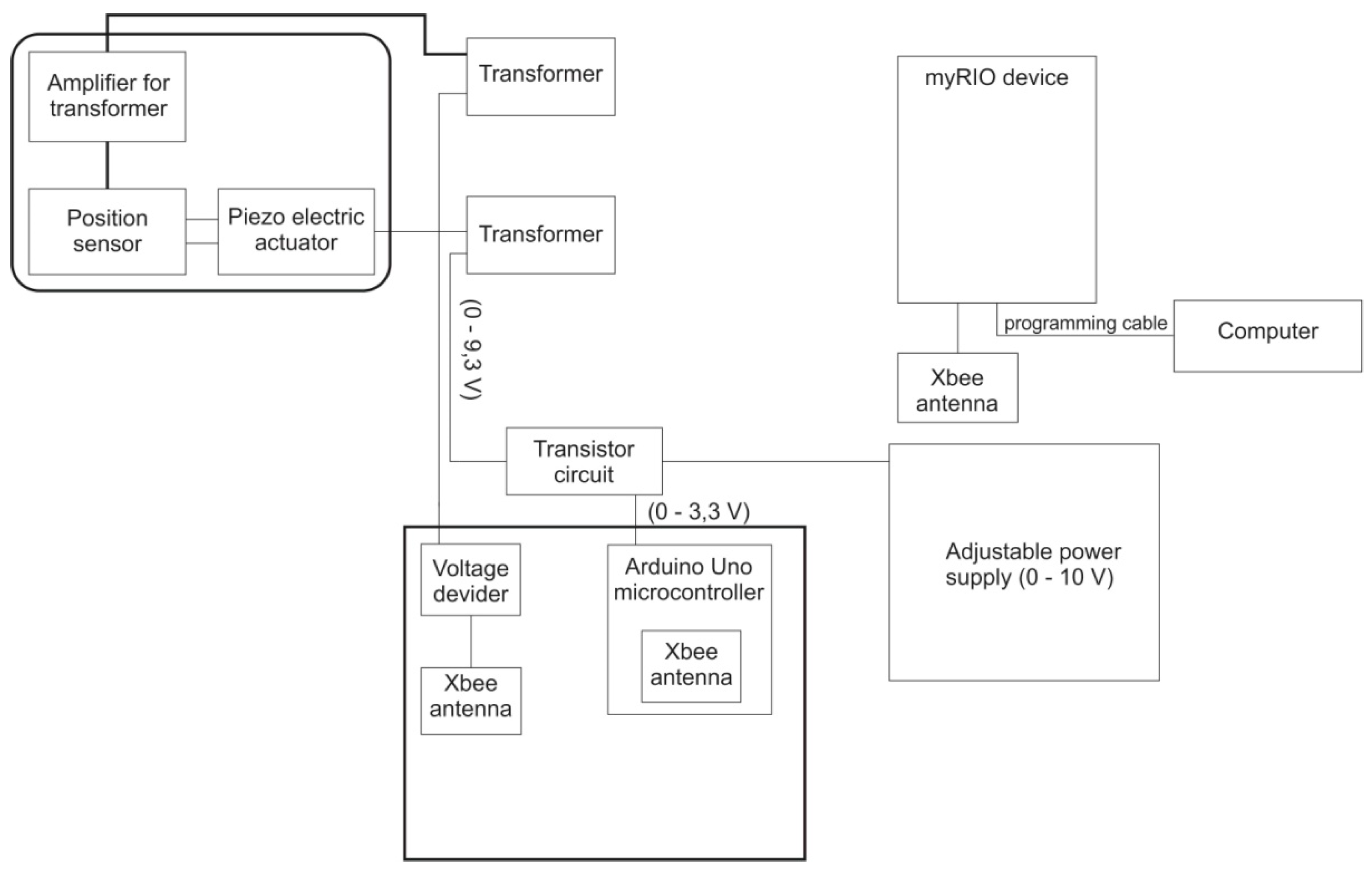
Figure 8 shows the layout of the experimental set up, which included the following major components—(1) the sensor; (2) the controller, and (3) the PEA actuator.
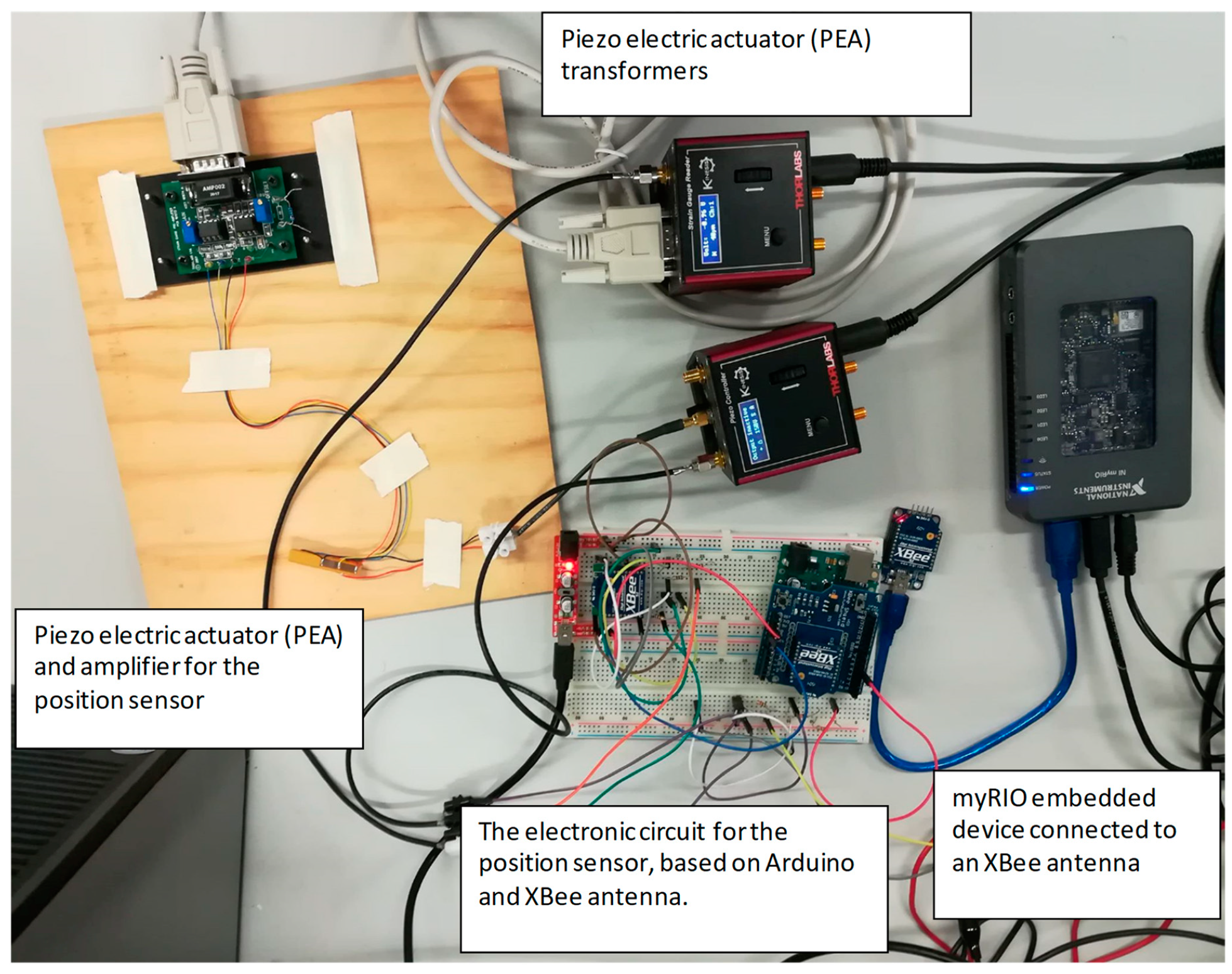
Figure 9 shows all of the devices involved in the experimental set up—in particular, the PEA itself, the driver, and the pre-amplifier, which were all supplied by the vendor, the ad-hoc amplifier circuit, the two XBee modules attached to the Arduino Uno, and the NI myRIO, respectively. The controller was implemented in LabVIEW, namely by means of the standard PID library provided in the LabVIEW. The PID module was tuned with the following parameters: Proportional Gain, Kc = 1, Integral Time, Ti = 0.001 min, and without Derivative Time, Td, since a simple PI controller was chosen.
The frames used to exchange information between the Arduino and the NI myRIO, followed the same format (shown in
Figure 2), as described in
Section 3.
5.2. Test Results
During the tests, the reference signal was created by the LabVIEW application executed at the NI myRIO and was sent to the PEA by means of the XBee communication. The PEA was positioned accordingly and the measured position was sent back to the LabVIEW program, which executed the PI algorithm aimed at correcting the position errors that occurred in the positioning process of the PEA. Several reference signals were used to analyze the behavior of the system in different situations. In particular, a ramp signal, a square signal, and a steady reference signal was used.
The first test illustrates the behavior of the system without using close loop control schemes, i.e., as an open loop process. In this test, it could be observed that when a closed loop controller was not used, the error between the reference and the measured value was steady and noticeable. For this test, it was around 25% of the reference value, so it was necessary to correct this error, see
Figure 10.
In the following tests, the controller was a basic PI controller, with a value of 1.000 for the proportional gain, Kc, while the integral time Ti, was set to 0.001 min.
Figure 11 shows the detail of one longer test, in which the system follows a ramp signal. The sampling frequency used in the test was 100 milliseconds and the duration of the shown sample was around 150 s. In this figure, the effect of the missed packages can be easily seen as the vertical orange lines out of the ramp input signal. In
Figure 11, seven missed messages that made around 0.5% of the sent messages can be seen. The analysis of several tests indicated that sometimes the packages were corrupted and other times these were not delivered correctly. For this reason, two mechanisms were introduced in the software, in order to detect these wrong or lost packages, namely (1) checking the integrity of the messages by means of the checksum sent in the XBee frames and (2) analyzing the sequence number to detect the missed packages. These mechanisms were introduced both in the NI myRIO LabVIEW program and the Arduino sketch. Additionally, it was necessary to introduce a policy to deal with the missed messages. The authors decided that a policy that would be easy to implement was to always store the last known value, so that in case of a missing message, the software could use the previous known value. Therefore, the remaining tests were executed with this policy implemented in the software.
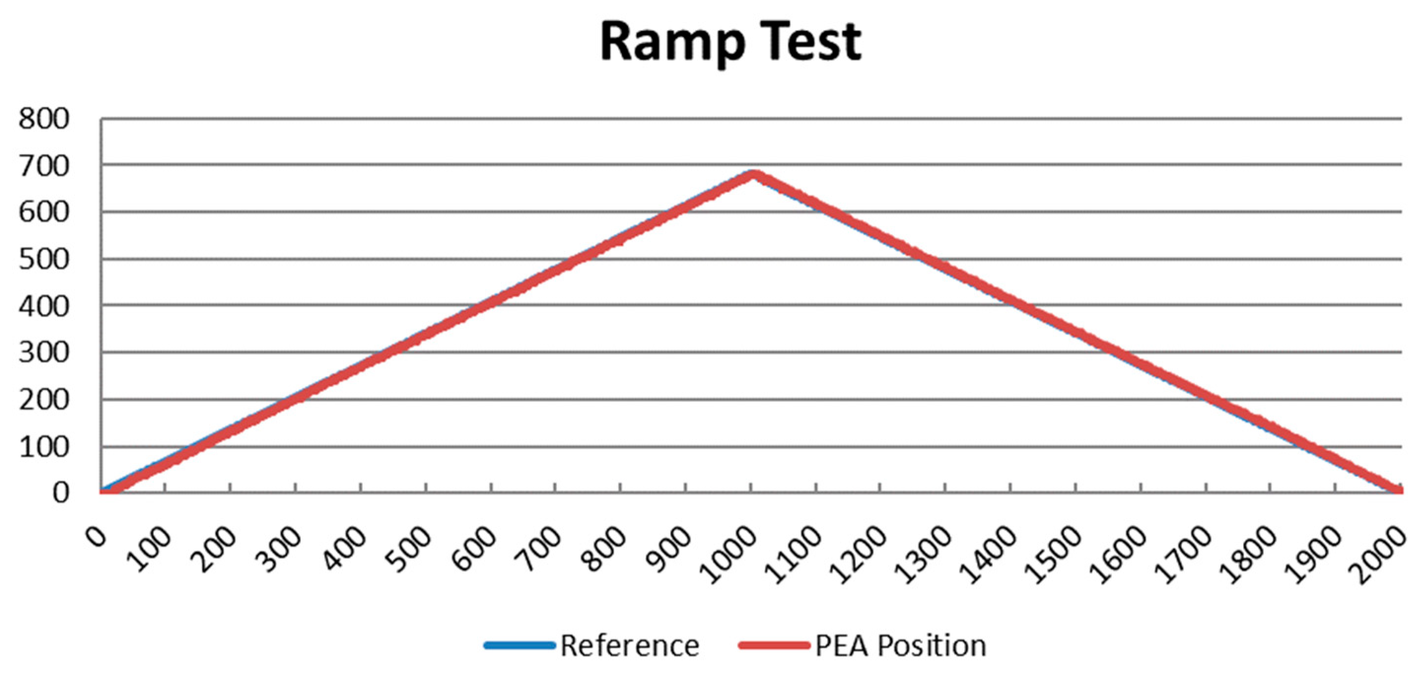
The following tests were performed at the following conditions: (1) 5 m distance between the controller, the LabVIEW program embedded in the NI myRIO, and the sensor/actuator block connected to the Arduino Uno; (2) a sampling period of 100 milliseconds, and (3) a resolution of 1023. These graphs show, both, the reference signal generated at the controller and the actual position variable, measured by the Arduino. These tests were executed with different reference signals in order to analyze the response of the PI in different situations.
The first test was executed for a duration of 200 s (2000 samples at 100 ms). This test was aimed at analyzing the behavior of the PI controller to smooth the reference variations. An ascending/descending ramp signal was used for this. The results of the test are shown in
Figure 12. Note that, both, the sent value (reference, generated at the controller) in blue, and the received value (PEA position measured by the integrated sensor) in red, are overlapping most of the time, even if with a short delay; identified in
Section 4.
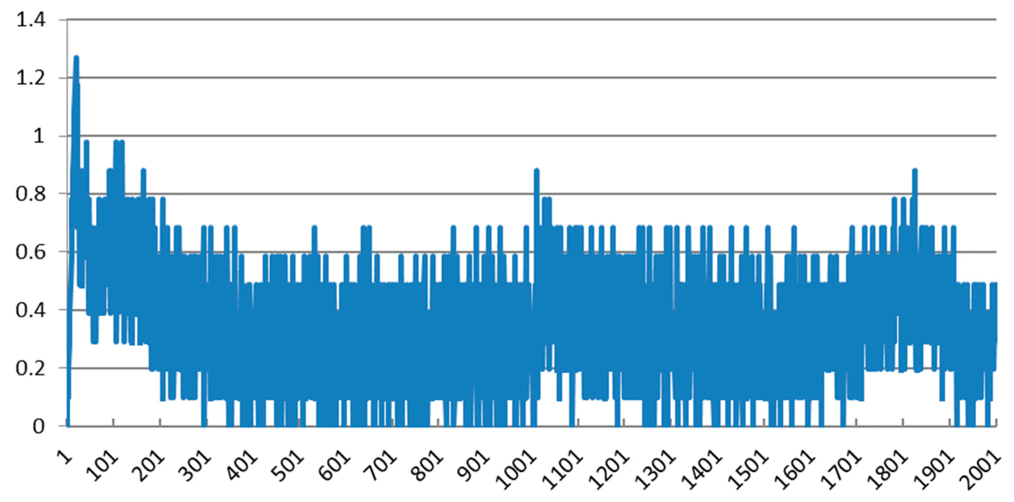
Figure 13 shows the percentage of the difference between both signals, the reference signal and the measured value over the maximum value, 1023. It can be seen that for this test, the error was below 1% of the maximum value (1023) almost for the whole test.
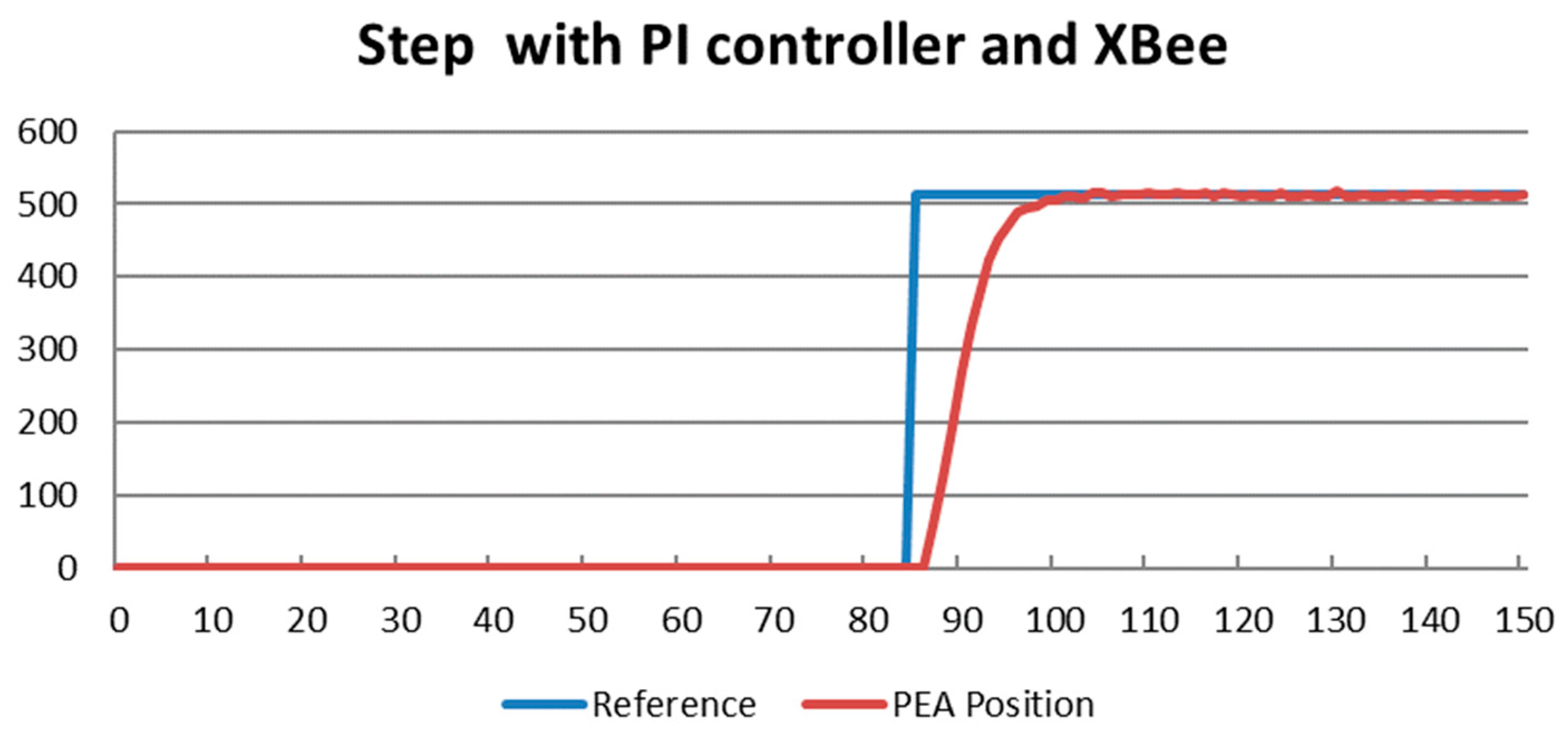
The second test was aimed at showing the behavior of the system when a strong control action was applied to the PEA. In this case, the reference position was changed from 0 to 512. In this case, the duration of the test was 15 s (150 samples at 100 ms), and it can be seen that it took some time to get the final position, due to the inertia of the system and the response of this specific controller, but the final error was very low, see
Figure 14.
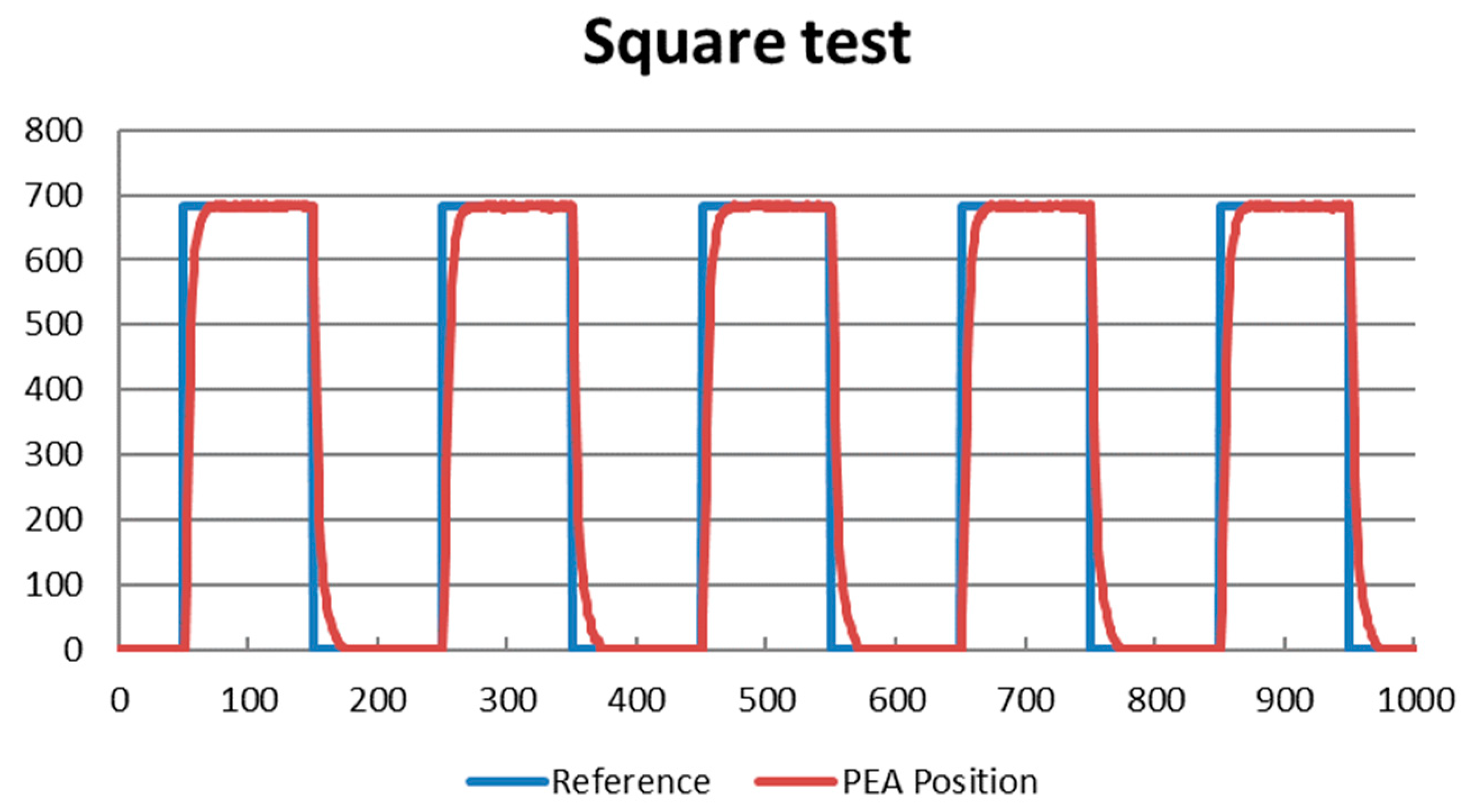
The following test was aimed at analyzing the behavior of the PEA when a square signal was used as reference for the PEA position. The square signal was aimed at alternatively keeping the position of the PEA for one second at a value of 682 and taking it back to the reference position. The duration of the test was of 100 s (1000 samples at 100 ms). The output of this test is shown in
Figure 15. It can be seen that the PEA position followed the reference signal without errors, even though it needed some time to reach the steady value due to the phenomenon of inertia.
5.3. Discussion
This section discusses the results of the tests aimed at analyzing the performance of the proposed wireless control scheme, for controlling the position of a PEA according to the layout described in
Section 3. A PI controller was selected for these tests but, obviously, other controller strategies could also have been used. All tests were carried out at 5 m distance with a sampling period of 100 ms. Different reference functions were used—ramp functions, for analyzing the behavior of the system to smooth changes, and step functions, for analyzing the behavior against more abrupt changes. The tests carried out and the obtained results have been summarized and some conclusions have been drawn below:
The open loop wireless response of the system was evaluated. In this test it was checked that without any close loop controller, the error between the reference and the measured value was noticeable (which was around the 25% of the reference value), which invalidated this approach at high precision applications.
The introduction of a wireless control scheme (implemented in LabVIEW) and its behavior when using a ramp reference was studied. No error detection mechanisms were implemented in this test. The results showed that the percentage of the detected missed/corrupted messages was around 0.5% of the delivered messages. Even though this percentage was not very high for this particular test, the experimental results discussed in
Section 4 showed that this percentage could reach higher values, potentially due to spurious interferences that depend on the environmental conditions. Consequently, some error detection mechanisms were included.
The behavior of the system when the error detection mechanisms were introduced in the wireless control scheme was also studied. These mechanisms were based on some fields included in the design of the frames, discussed in
Section 3 (i.e., checksum and sequence number). A ramp reference signal was used to reproduce the smooth changes. In this test, the percentage difference between the reference and the PEA measured position was below the 1% or even less.
The behavior of the system to abrupt changes was also analyzed. For this purpose, a short test with a step reference of 50% of the maximum reference value was carried out. In this test, the delay introduced by the system could be appreciated due to the sampling period of 100 ms, and the inertia phenomena that came up in the PEA. However, in the permanent state, the error measured in the system was always below the 0.5% of the scale.
The repeatability of the system was studied. For this purpose, a square signal was used as reference. The square signal ranged between 0 and the 66% of the maximum reference value. The behavior of the response did not present relevant changes from the previous test.
These tests showed that a close loop controller was needed. Since the authors focused on the analysis of wireless communications for the control applications, they chose one simple, well-known controller, more specifically a PI controller, even though the performance of the system could have been improved by using more advanced control strategies, such as [
33,
34]. In the experiments discussed, the error of the PEA positioning system was eliminated for a constant reference, as expected, since the PI controllers, if properly tuned, permanently eliminated the error. The tests showed that the response of the selected PI controller for this control scheme was especially adequate, when the reference signal changed smoothly. In addition, some mechanisms were introduced to deal with missed or corrupted packages, improving the performance of the whole system.
The results showed that wireless technologies introduce significant delay (around 46 ms were measured in
Section 4 for two-way communication). However, the jitter was quite steady since the standard deviation of the delay measured in the tests was relatively low (around 5 ms). In the presented tests, a sampling period (100 ms) which was much bigger than the expected communication delay (46 ms) could, in part, mask the communication delay. In other words, if the delay was steady and considerably lower than the sampling period this became the most relevant parameter for the control scheme. In such a case, there should not have been any problem with the performance of the wireless control scheme, from the communications perspective. On the contrary, if the delay were much higher than the sampling period, the stability of the system could be affected. Some authors [
33,
34] have analyzed this issue and have proposed using different techniques such as the Smith predictor or Kalman filters, in order to compensate the communication delay in the control scheme.
6. Conclusions
During the last years, wireless technologies have experimented with important advances and currently they have been frequently adopted at non-critical applications, even in conservative environments such as those found in industrial applications. They are considered to be one of the key enablers of Industry 4.0. However, they are still under scrutiny for acceptance in more critical applications, for example those that involve closed-loop control applications. Since they are still in an incipient stage for this kind of application, in the course of the following years new technologies specifically aimed at industrial environments are expected to come up to the market. In this scenario, the rationale behind this article was to present experimental use cases of wireless control systems that could help the scientific community to efficiently design and implement new control systems.
In particular, this article analyzed the implementation of one of the most popular wireless technologies available nowadays, namely the XBee 2.4 GHz technology, in closed-loop control applications. For this purpose, several experiments were carried out to analyze its applicability. In particular the following were evaluated—(1) the performance of Analog-to-Digital Converters provided by the XBee modules, (2) the offset and message dropout rate at several distances and sampling periods; (3) the message delay introduced by this technology and, finally, (4) the influence of Wi-Fi interferences was checked experimentally. For this purpose, wireless communications were compared with wired communications by means of a one NI myDAQ USB-6008 board. Wired communications were used as the reference communication system to compare with the wireless communications. The transmission delay measured at the experiments was significantly increased, when compared to wired communications. The dropout rate obtained in the experimental tests was around the 2% of the transmitted packages, which was sensitive to environmental conditions. In particular, one important issue was that, other common communication technologies such as Wi-Fi, introduced spurious interferences that could potentially increase the transmission error bit rate; as confirmed by the experiments. It might be interesting to analyze the introduction of variations of XBee technology that work at different transmission frequency bands (such as 868 and 900 MHz), in industrial environments. After this discussion, it could be concluded that for non-critical systems, or only for monitoring purposes, XBee 2.4 GHz might be a viable alternative, but in more critical applications it is necessary to carefully analyze its introduction.
In this study, the network topology, the design of the frames, the process to detect missed/corrupted frames, based on the frame design, and the procedure to minimize the effect of wrong messages were presented. Additionally, the integration of different technologies used for connecting a generic wireless sensor/actuator to a controller which was implemented with LabVIEW.
In order to show the application of wireless technologies to a real scenario, the authors presented a high precision micro-positioning application in which a piezoelectric actuator (PEA) was involved. This actuator presented strong nonlinearities that made difficult to implement a high performance controller. However, since the objective of this work was to analyze the application of the XBee communication in closed-loop control systems, a proportional-integral (PI) controller was used. All tests were executed at a frequency of 100 milliseconds and at a distance of 5 m between the controller and the actuator. The results showed that, even with some limitations, the combination of a closed-loop controller, implemented in LabVIEW in a NI myRIO platform, and the use of XBee 2.4 GHz modules were found to be effective. Several tests were carried out in this research. The first test was aimed at analyzing the behavior of the PEA without any controller. In the second test, a PI controller was introduced and there were no introduced error detection mechanisms. Thus, wrong and missed communication packages were identified. In the following tests, error detection mechanisms were introduced and, in the case of detecting a wrong or missed package, the policy of keeping the last known value was set. Several reference signals were used, namely an ascending/descending ramp for analyzing the response of the control scheme to smooth changes, a step for analyzing the response of the control scheme to abrupt changes, and a square reference to analyze the repeatability. The results proved that the error of the system might be eliminated even though for strong control actions, it might take some time to achieve it.

 ,
, 


