A Coordinated Dual-Channel Wide Area Damping Control Strategy for a Doubly-Fed Induction Generator Used for Suppressing Inter-Area Oscillation


Abstract
:1. Introduction
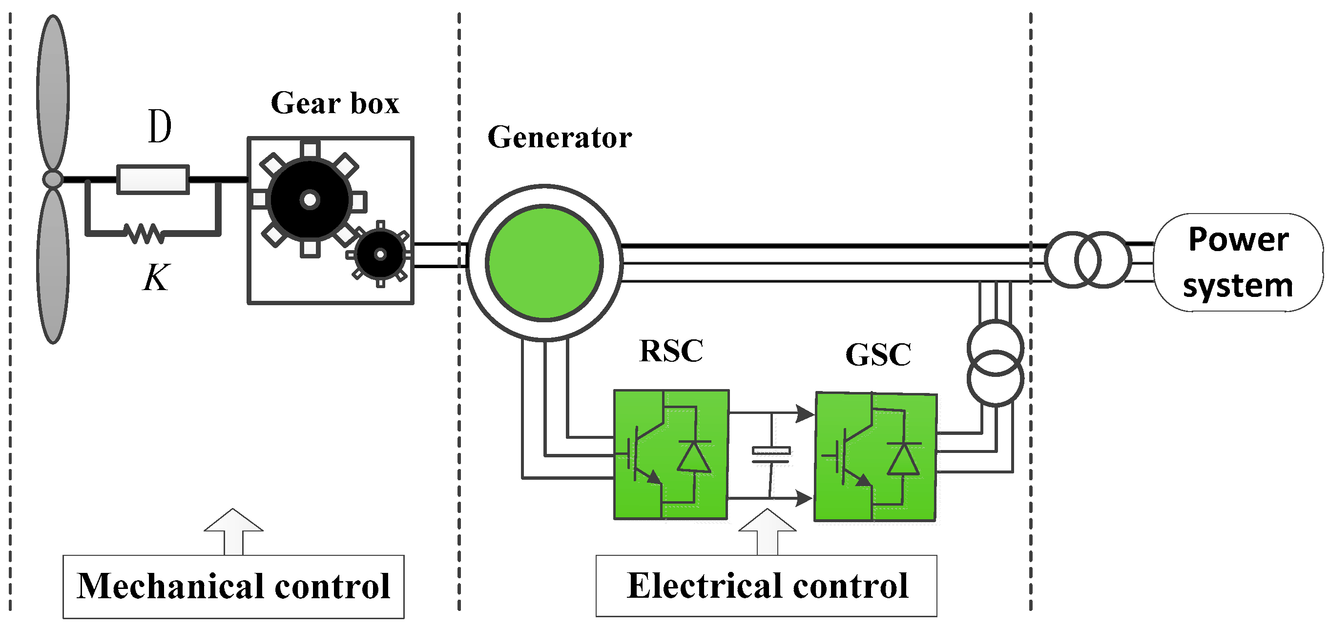
2. System Modeling
2.1. Aerodynamic Model
2.2. Wind Turbine Torsional Dynamics Model
2.3. DFIG Model
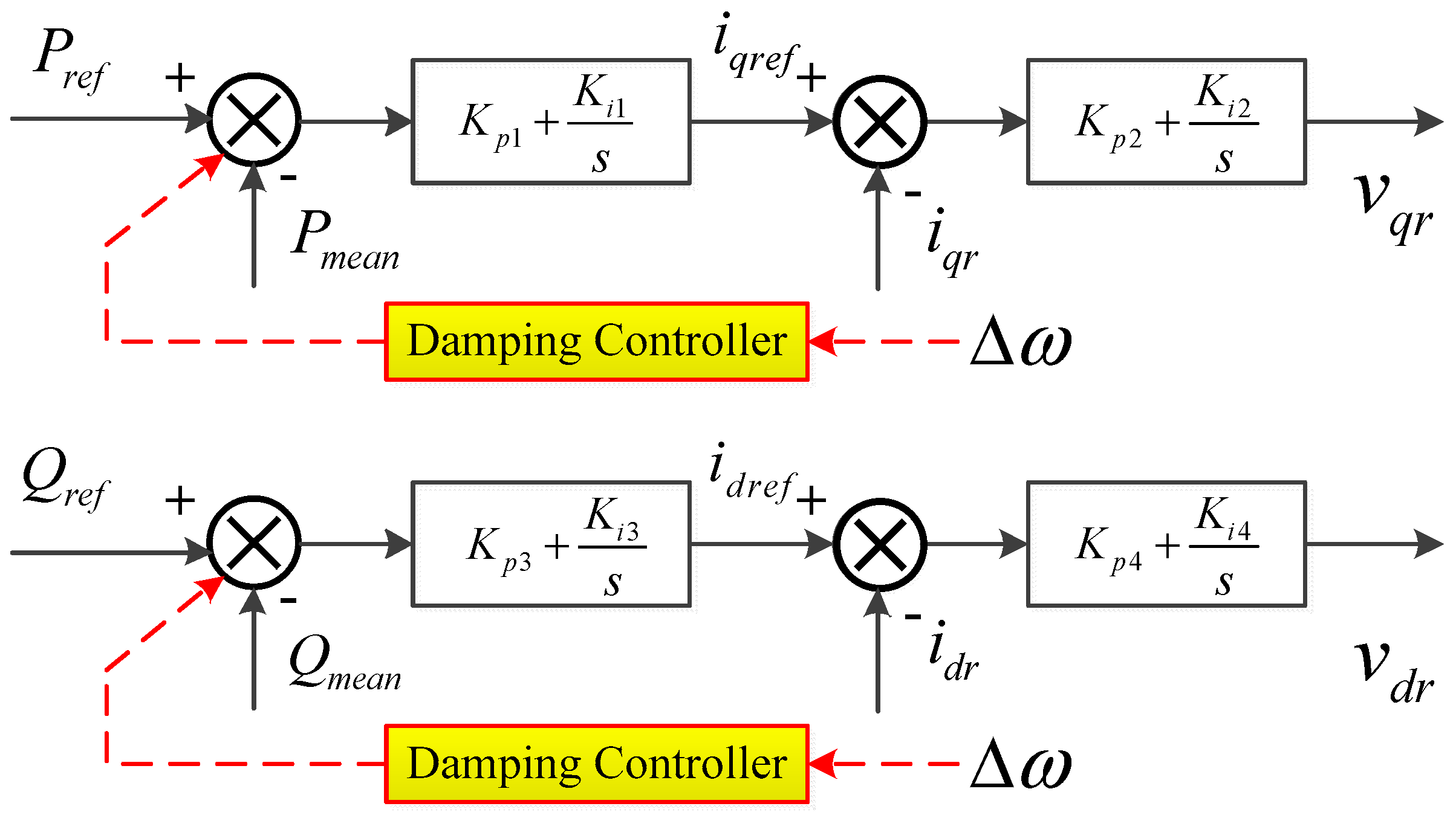
3. Basic Principle of Additional Damping Control for DFIG
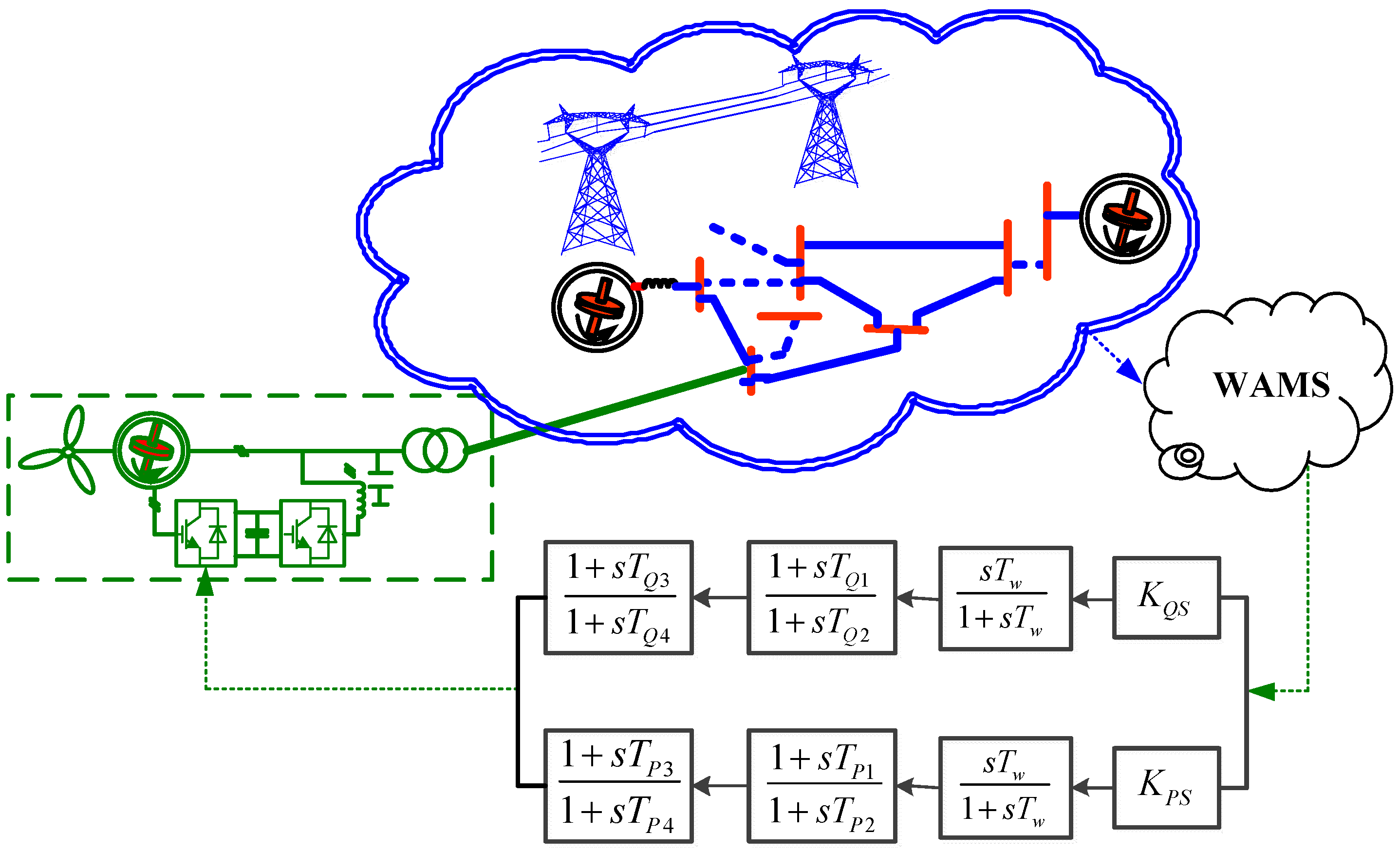
4. Optimal Tuning of Damping Controllers
4.1. Controller Structure
4.2. Formulation of Optimization Problem
5. Simulation Results and Discussion
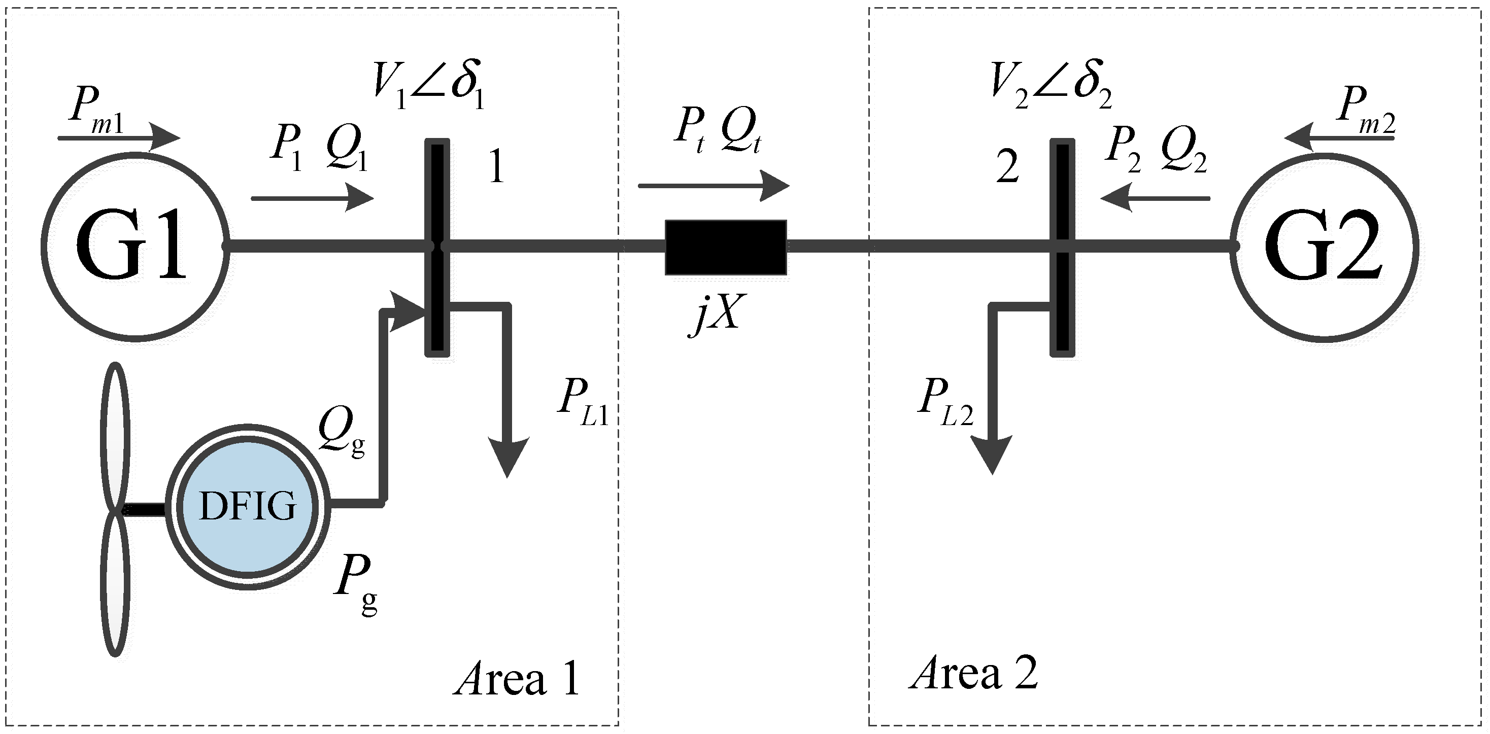
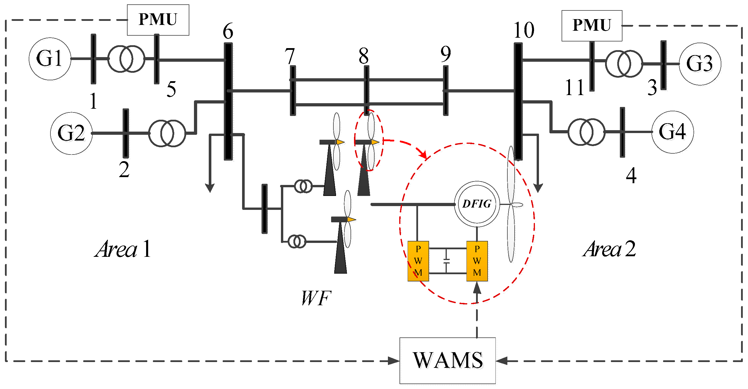
5.1. Evaluation in Two-Area Four-Machine System
5.2. Parameter of Damping Controller
5.3. Simulations and Analysis Under Different Circumstances
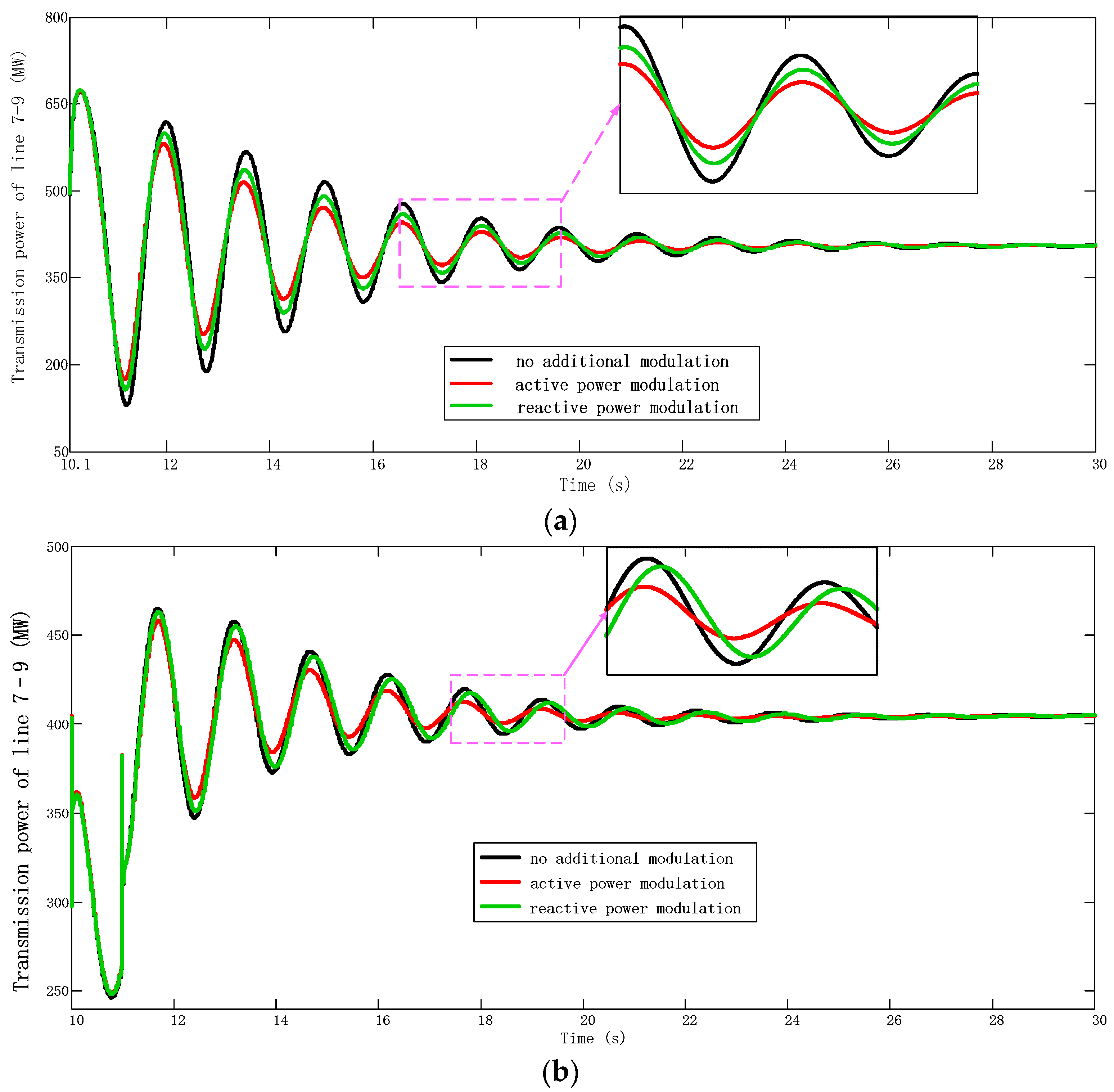
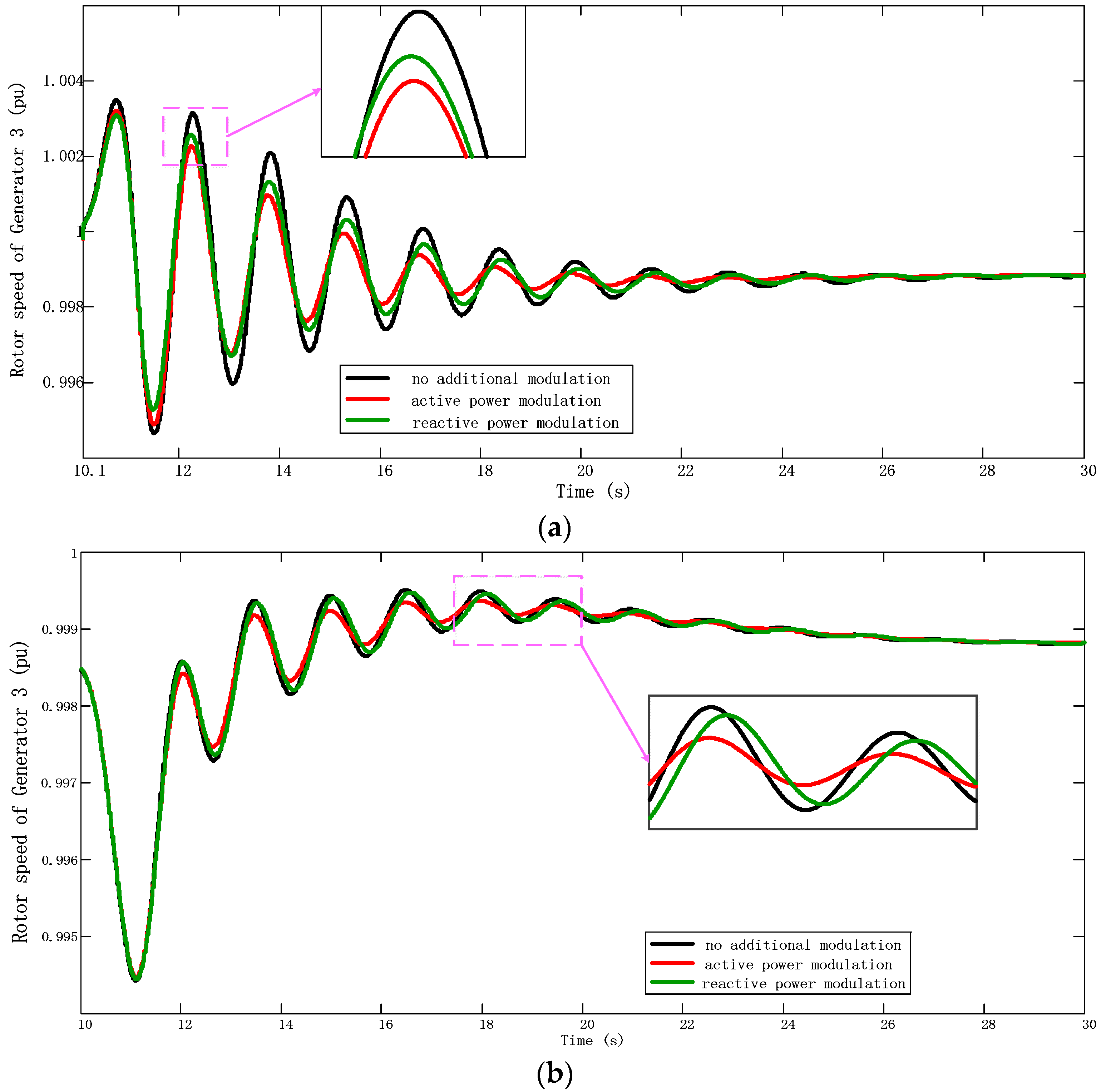
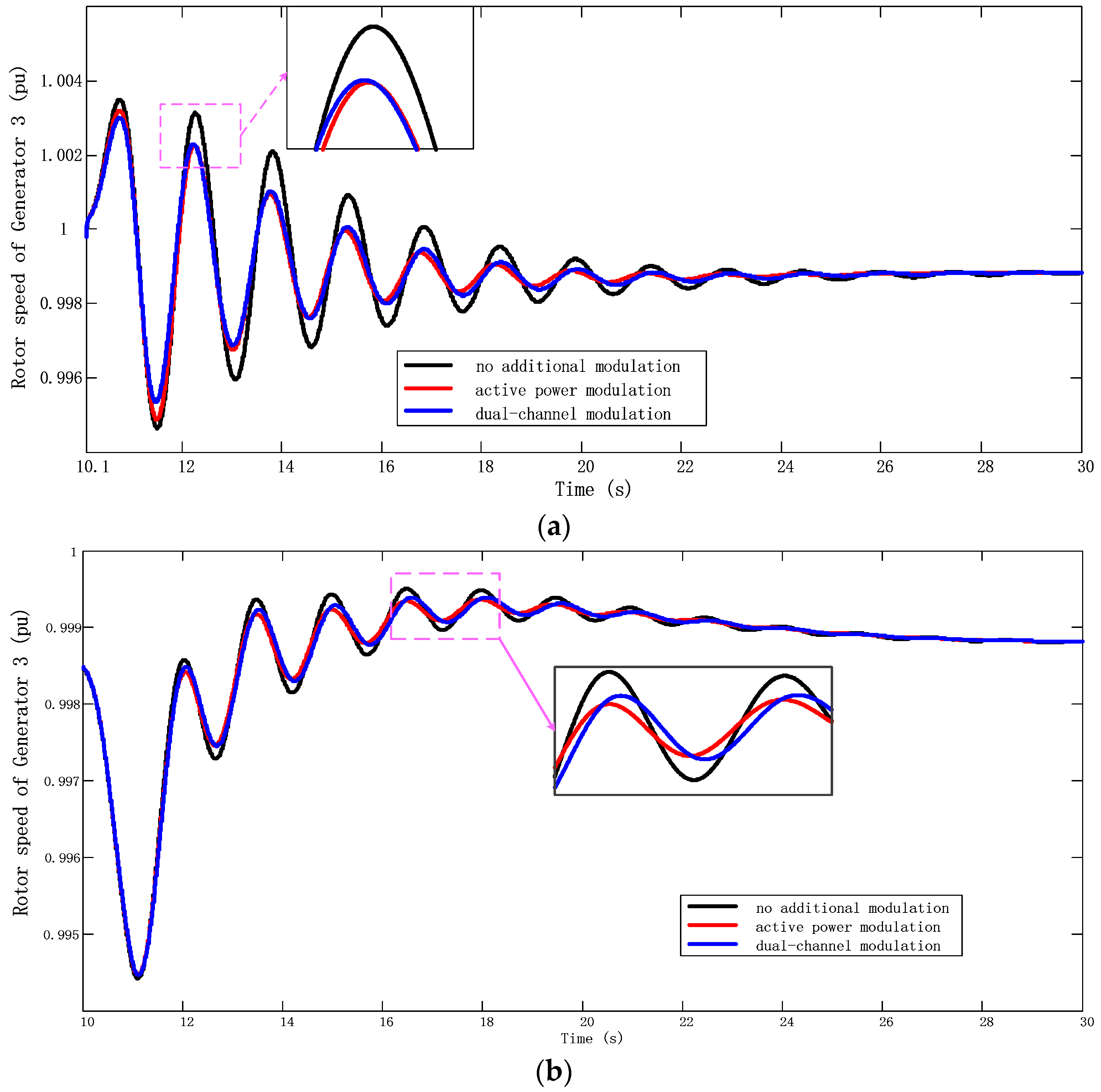
5.3.1. Compare APM and RPM
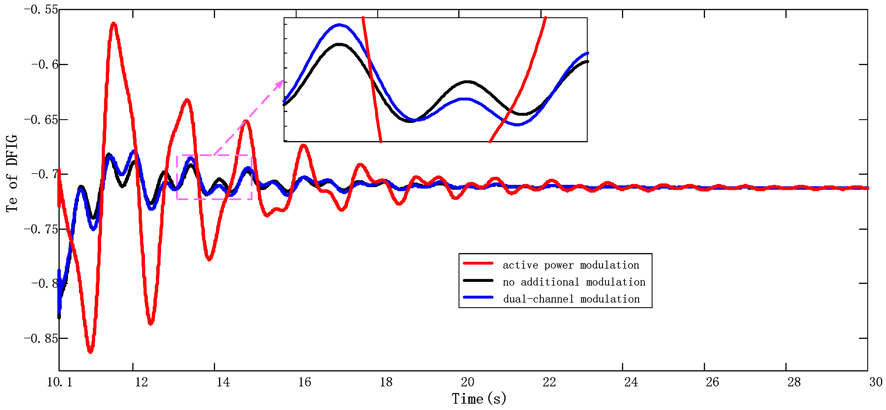
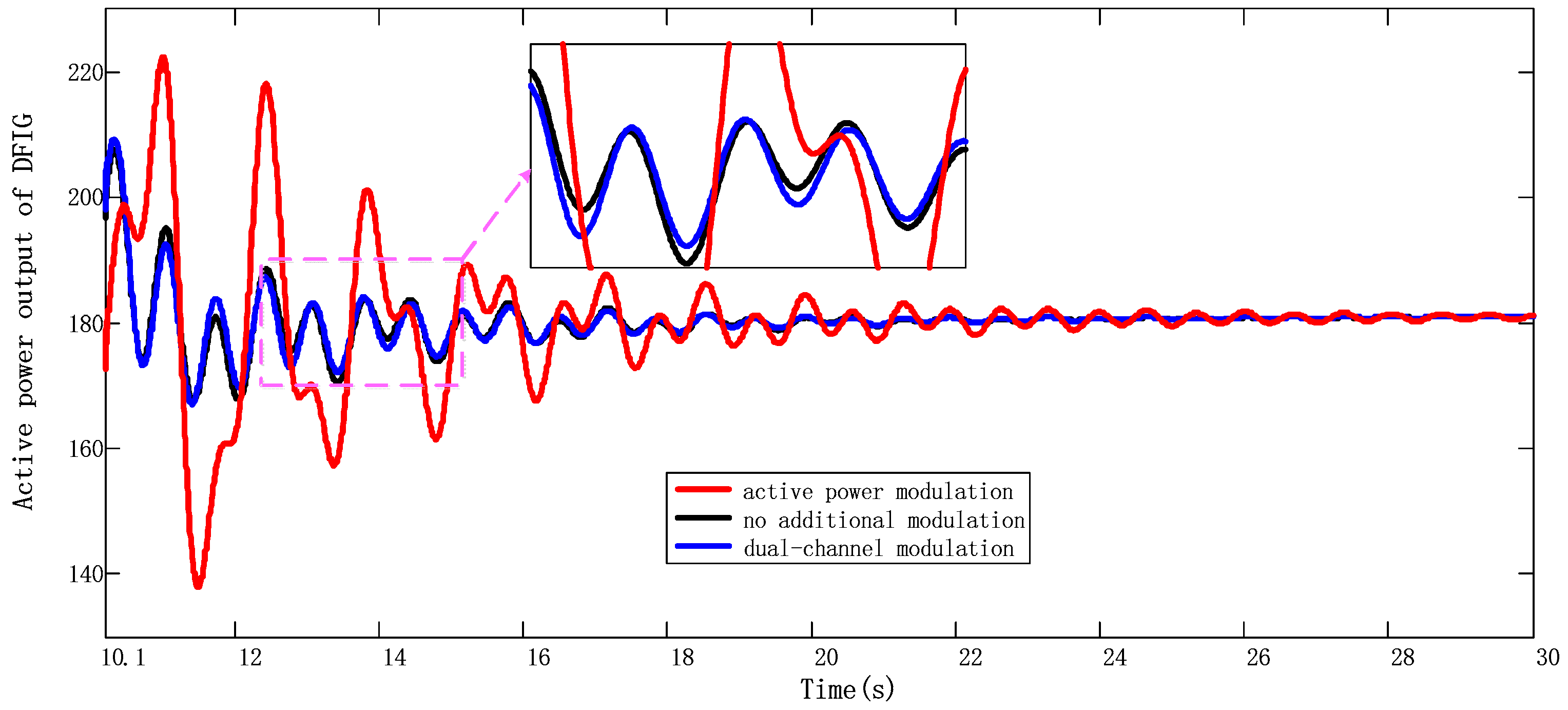
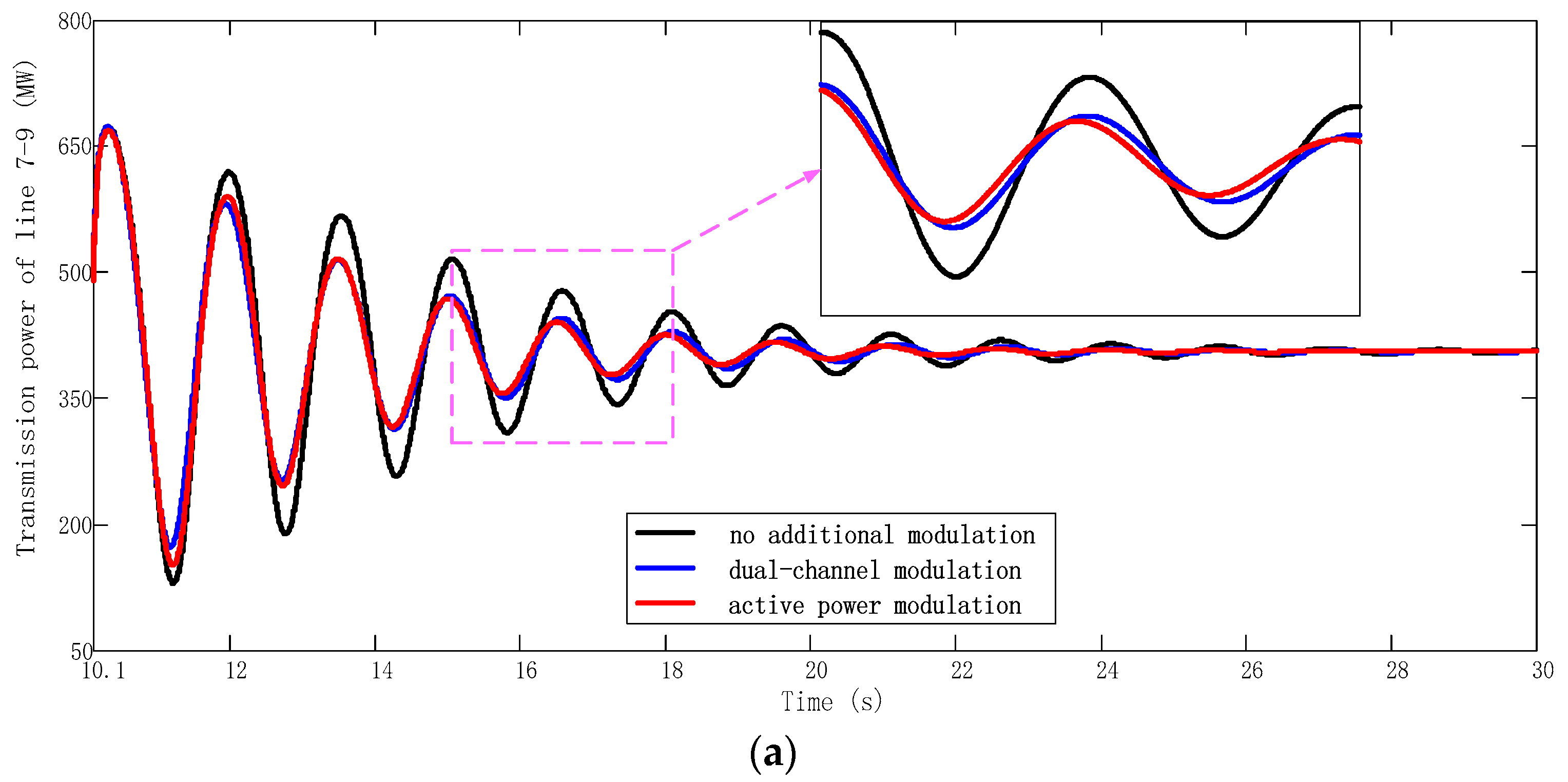
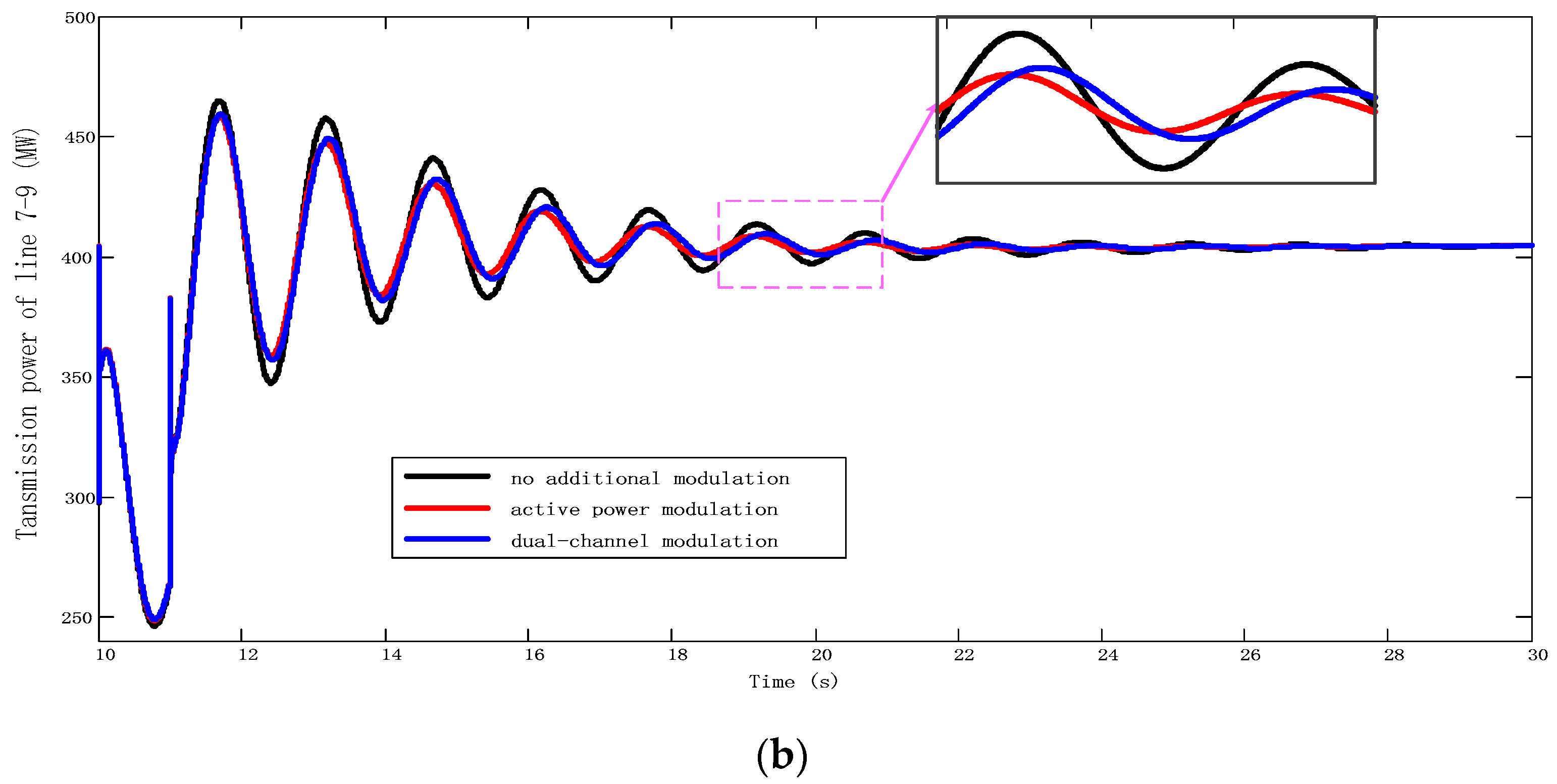
5.3.2. Compare APM and DCPM
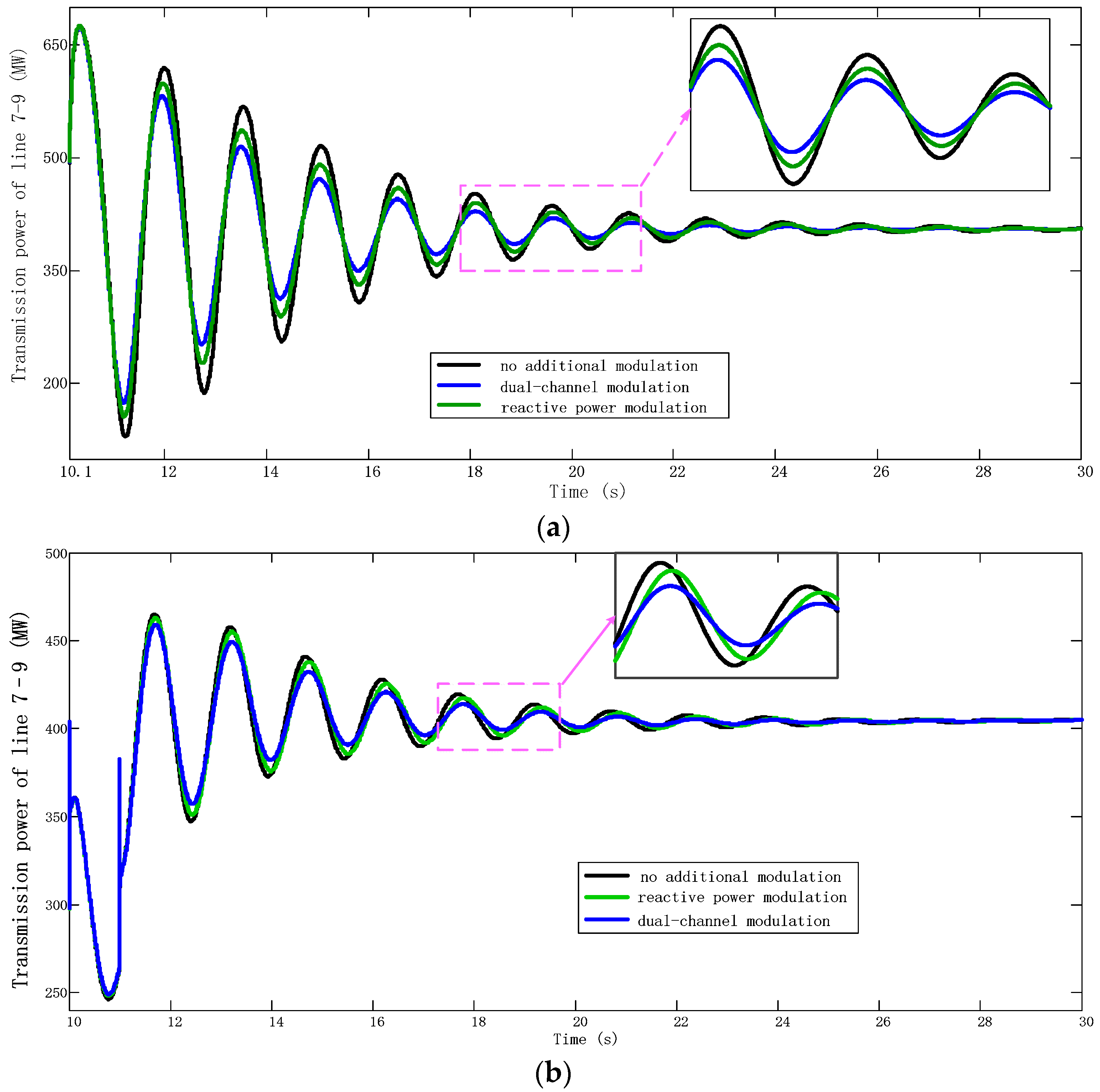
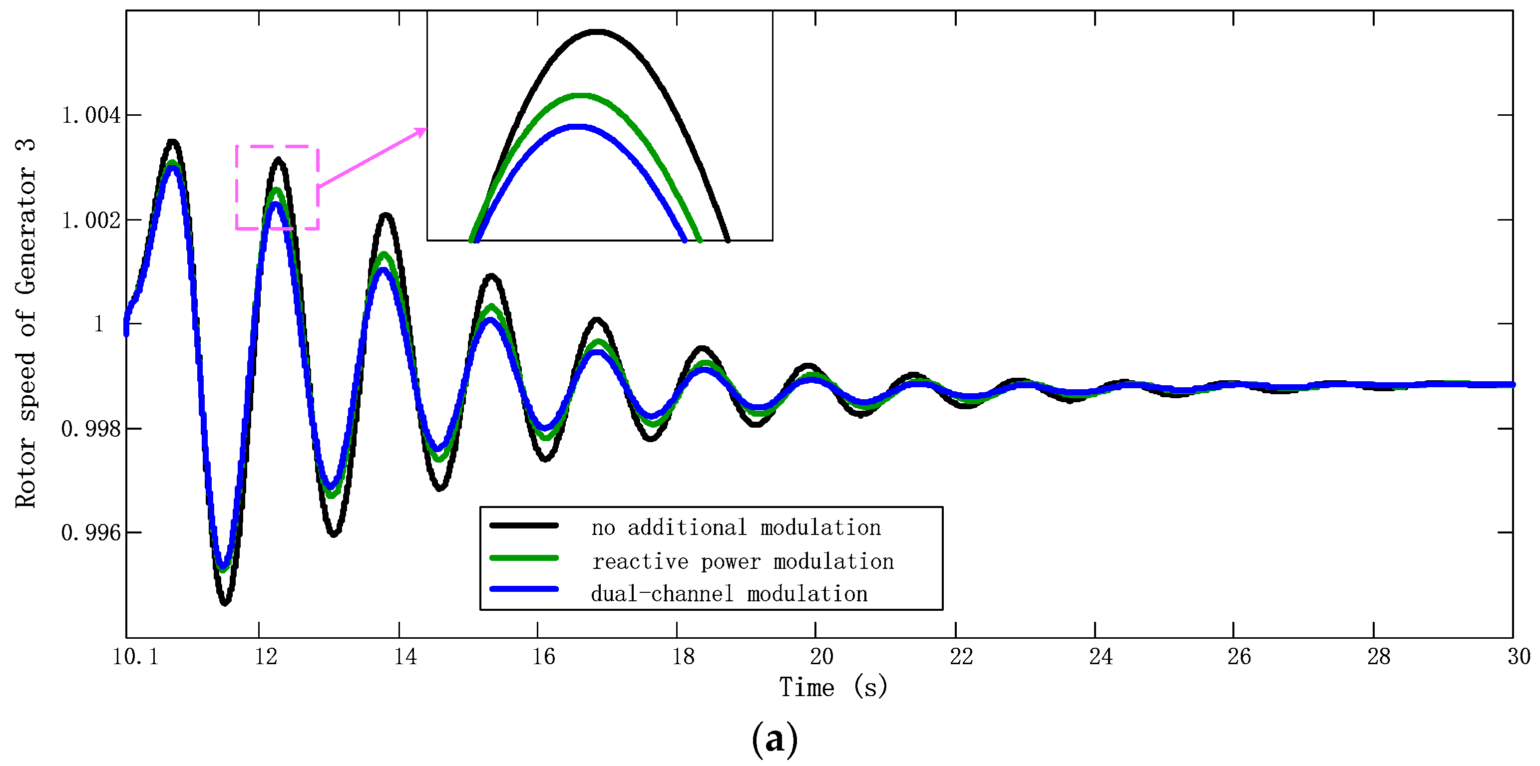
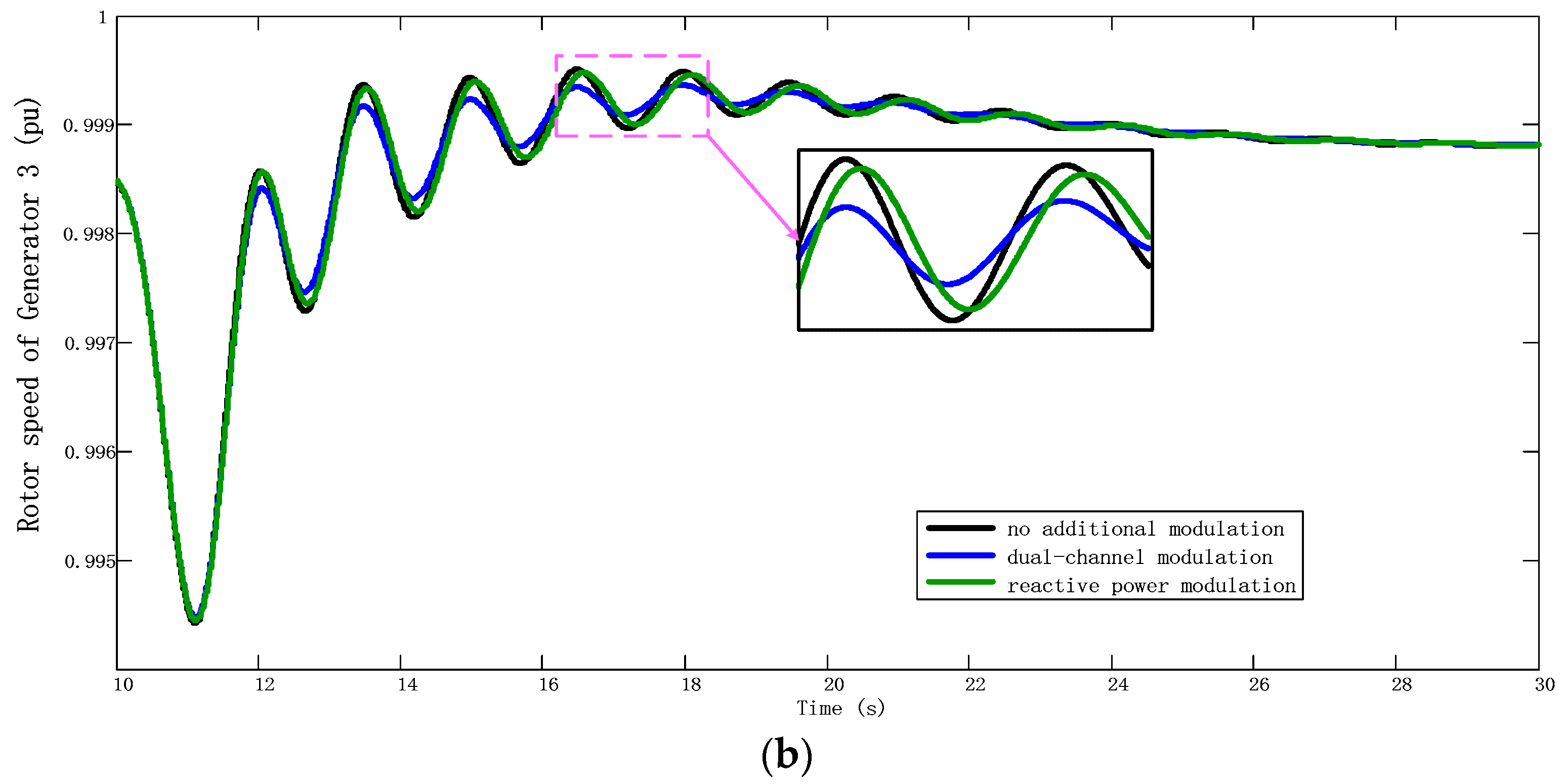
5.3.3. Compare RPM and DCPM
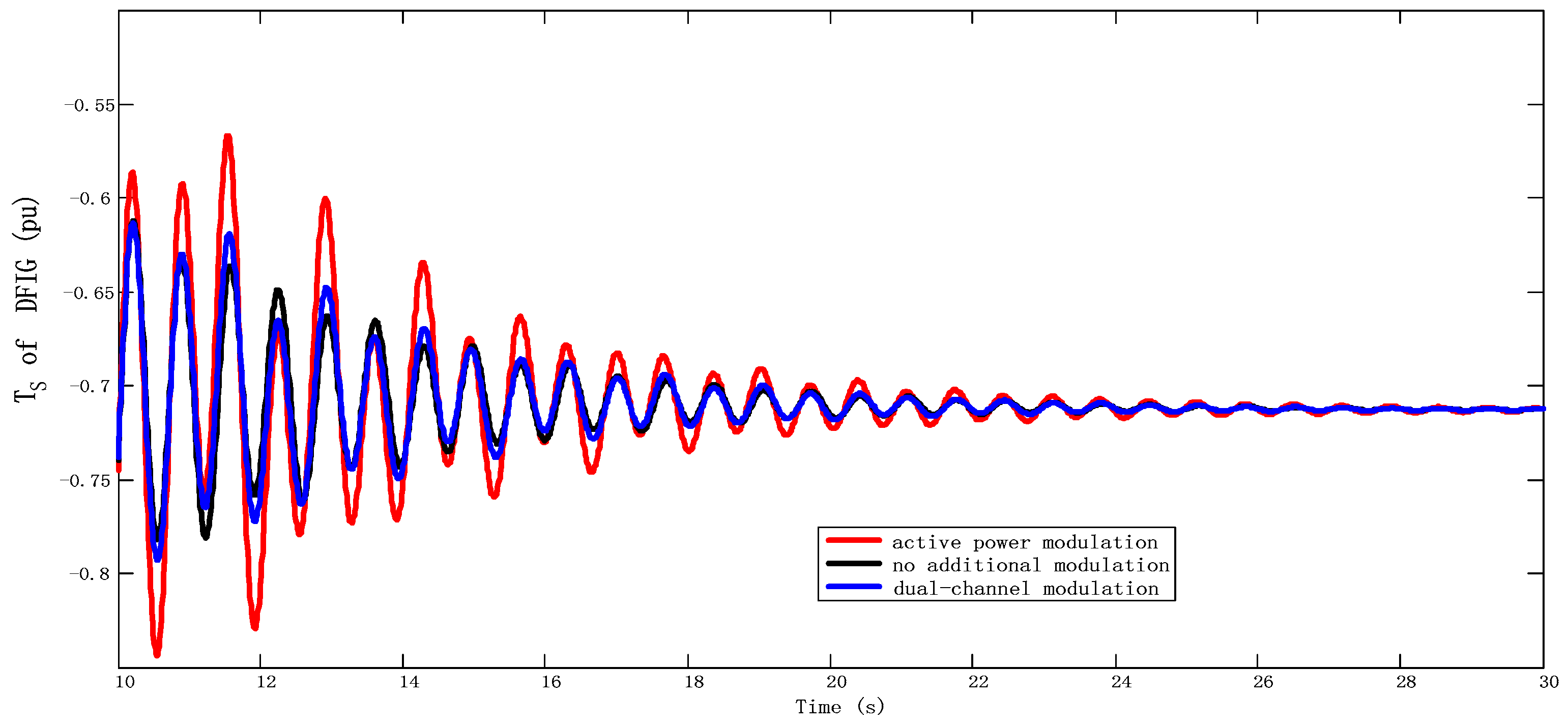
5.3.4. DFIG’s Shaft Dynamic after Additional Control
6. Conclusions
Author Contributions
Funding
Conflicts of Interest
Appendix A

Appendix B
References
- Islam, M.R.; Guo, Y.; Zhu, J. A review of offshore wind turbine nacelle: Technical challenges, and research and developmental trends. Renew. Sustain. Energy Rev. 2014, 33, 161–176. [Google Scholar] [CrossRef]
- Muller, S.; Deicke, M.; De Doncker, R.W. Doubly fed induction generator systems for wind turbines. IEEE Ind. Appl. Mag. 2002, 8, 26–33. [Google Scholar] [CrossRef]
- Yanfeng, M.; Jia, L.; Haihang, L. Active-Reactive Additional Damping Control of a Doubly-Fed Induction Generator Based on Active Disturbance Rejection Control. Energies 2018, 11, 1314–1331. [Google Scholar]
- Domínguez-García, J.L.; Gomis-Bellmunt, O.; Bianchi, F.D. Power oscillation damping supported by wind power: A review. Renew. Sustain. Energy Rev. 2012, 16, 4994–5006. [Google Scholar] [CrossRef]
- Hughes, F.M.; Anaya-Lara, O.; Jenkins, N. A power system stabilizer for DFIG-based wind generation. IEEE Trans. Power Syst. 2006, 21, 763–772. [Google Scholar] [CrossRef]
- Miao, Z.; Fan, L.; Osborn, D. Control of DFIG-Based Wind Generation to Improve Interarea Oscillation Damping. IEEE Trans. Energy Convers. 2009, 24, 415–422. [Google Scholar] [CrossRef]
- Tan, A.; Lin, X.; Sun, J. A Novel DFIG Damping Control for Power System with High Wind Power Penetration. Energies 2016, 9, 521. [Google Scholar] [CrossRef]
- Fan, L.; Yin, H.; Miao, Z. On Active/Reactive Power Modulation of DFIG-Based Wind Generation for Interarea Oscillation Damping. IEEE Trans. Energy Convers. 2011, 26, 513–521. [Google Scholar]
- Tsourakis, G.; Nomikos, B.M.; Vournas, C.D. Contribution of Doubly Fed Wind Generators to Oscillation Damping. IEEE Trans. Energy Convers. 2009, 24, 783–791. [Google Scholar] [CrossRef]
- Liao, K.; He, Z.; Xu, Y. A Sliding Mode Based Damping Control of DFIG for Interarea Power Oscillations. IEEE Trans. Sustain. Energy 2016, 8, 258–267. [Google Scholar] [CrossRef]
- Kundur, P. Power System Stability and Control, 1st ed.; McGraw-Hill: New York, NY, USA, 1994; pp. 1128–1160. [Google Scholar]
- Mokhtari, M.; Aminifar, F. Toward Wide-Area Oscillation Control Through Doubly-Fed Induction Generator Wind Farms. IEEE Trans. Power Syst. 2014, 29, 2985–2992. [Google Scholar] [CrossRef]
- Xi, X.; Geng, H.; Yang, G. Modelling of the DFIG Based Wind Farms for Small Signal Stability Analysis of Weak Power Grids. In Proceedings of the Renewable Power Generation Conference IET, Beijing, China, 9–11 September 2013. [Google Scholar]
- Li, H.; Chen, H.; Yang, C. Ancillary damping control strategy for wind farms with doubly-fed induction generators using power signals in transmission lines. Autom. Electr. Power Syst. 2012, 36, 28–33. [Google Scholar]
- Geng, H.; Xi, X.; Liu, L. Hybrid Modulated Active Damping Control for DFIG based Wind Farm Participating in Frequency Response. IEEE Trans. Energy Convers. 2017, 32, 1220–1230. [Google Scholar] [CrossRef]
- Lei, T.; Barnes, M.; Ozakturk, M. Doubly-fed induction generator wind turbine modelling for detailed electromagnetic system studies. IET Renew. Power Gener. 2013, 7, 180–189. [Google Scholar] [CrossRef]
- Liao, K.; Xu, Y.; Wang, Y. Hybrid fast damping control strategy for doubly fed induction generators against power system inter-area oscillations. IET Renew. Power Gener. 2018, 12, 463–471. [Google Scholar] [CrossRef]
- Nguyen-Duc, H.; Dessaint, L.; Okou, A.F. A Power Oscillation Damping Control Scheme Based on Bang-Bang Modulation of FACTS Signals. IEEE Trans. Power Syst. 2010, 25, 1918–1927. [Google Scholar] [CrossRef]
- Sunkara, S.K.; Narne, R.; Panda, P.C. Coordinated Tuning of PSS with TCSC Damping Controller Through Advanced Adaptive PSO for a Multi-Machine Power System. In Proceedings of the 2013 International Conference on Energy Efficient Technologies for Sustainability, Nagercoil, India, 10–12 April 2013. [Google Scholar]
- Ratnaweera, A.; Halgamuge, S.K.; Watson, H.C. Self-Organizing Hierarchical Particle Swarm Optimizer with Time-Varying Acceleration Coefficients. IEEE Trans. Evolut. Comput. 2004, 8, 240–255. [Google Scholar] [CrossRef]
- Fan, L.; Feliachi, A.; Schoder, K. Selection and design of a TCSC control signal in damping power system inter-area oscillations for multiple operating conditions. Electr. Power Syst. Res. 2002, 62, 127–137. [Google Scholar] [CrossRef]
- Larsen, E.V.; Sanchezgasca, J.J.; Chow, J.H. Concepts for design of facts controllers to damp power swings. IEEE Trans. Power Syst. 1995, 10, 948–956. [Google Scholar] [CrossRef]
- Zhang, C.; Ke, D.; Sun, Y. Coordinated Supplementary Damping Control of DFIG and PSS to Suppress Inter-Area Oscillations with Optimally Controlled Plant Dynamics. IEEE Trans. Sustain. Energy 2018, 9, 780–791. [Google Scholar] [CrossRef]


| Modulation Type | Channel | Gain | T1 | T2 | T3 | T4 |
|---|---|---|---|---|---|---|
| DCPM | active | 10.2 | 0.079 | 0.22 | 0.081 | 0.21 |
| reactive | 48.3 | 0.081 | 0.21 | 0 | 0 | |
| APM | active | 50 | 0.078 | 0.21 | 0.081 | 0.21 |
| RPM | reactive | 50 | 0.081 | 0.21 | 0 | 0 |
| Control Mode. | Inter-area Oscillation Frequency/Hz | Damping (%) | Shaft Oscillation Frequency/Hz | Damping (%) |
|---|---|---|---|---|
| No | 0.65 | 1.21 | 1.82 | 7.21 |
| DCPM | 0.65 | 8.05 | 1.82 | 6.52 |
| APM | 0.64 | 8.11 | 1.82 | 4.13 |
| RCM | 0.65 | 5.21 | 1.82 | 7.23 |
© 2019 by the authors. Licensee MDPI, Basel, Switzerland. This article is an open access article distributed under the terms and conditions of the Creative Commons Attribution (CC BY) license (http://creativecommons.org/licenses/by/4.0/).
Share and Cite
Cai, G.; Chen, X.; Sun, Z.; Yang, D.; Liu, C.; Li, H. A Coordinated Dual-Channel Wide Area Damping Control Strategy for a Doubly-Fed Induction Generator Used for Suppressing Inter-Area Oscillation. Appl. Sci. 2019, 9, 2353. https://doi.org/10.3390/app9112353
Cai G, Chen X, Sun Z, Yang D, Liu C, Li H. A Coordinated Dual-Channel Wide Area Damping Control Strategy for a Doubly-Fed Induction Generator Used for Suppressing Inter-Area Oscillation. Applied Sciences. 2019; 9(11):2353. https://doi.org/10.3390/app9112353
Chicago/Turabian StyleCai, Guowei, Xiangsong Chen, Zhenglong Sun, Deyou Yang, Cheng Liu, and Haobo Li. 2019. "A Coordinated Dual-Channel Wide Area Damping Control Strategy for a Doubly-Fed Induction Generator Used for Suppressing Inter-Area Oscillation" Applied Sciences 9, no. 11: 2353. https://doi.org/10.3390/app9112353
APA StyleCai, G., Chen, X., Sun, Z., Yang, D., Liu, C., & Li, H. (2019). A Coordinated Dual-Channel Wide Area Damping Control Strategy for a Doubly-Fed Induction Generator Used for Suppressing Inter-Area Oscillation. Applied Sciences, 9(11), 2353. https://doi.org/10.3390/app9112353