Article

Seismic Design of Steel Moment-Resisting Frames with Damping Systems in Accordance with KBC 2016

1
Graduate Student in Department of Architecture, Incheon National University, Incheon 22012, Korea
2
Professor in Division of Architecture and Urban Design, Incheon National University, Incheon 22012, Korea
*
Author to whom correspondence should be addressed.
Appl. Sci. 2019, 9(11), 2317; https://doi.org/10.3390/app9112317
Submission received: 26 April 2019 / Revised: 22 May 2019 / Accepted: 31 May 2019 / Published: 5 June 2019
(This article belongs to the Special Issue Buildings and Structures under Extreme Loads)

Abstract

:
An efficient design procedure for building structures with damping systems is proposed using nonlinear response history analysis permitted in the revised Korean building code, KBC 2016. The goal of the proposed procedure is to design structures with damping systems complying with design requirements of KBC 2016 that do not specify a detailed design method. The proposed design procedure utilizes response reduction factor obtained by a limited number of nonlinear response history analyses of the seismic-force-resisting system with incremental damping ratio substituting damping devices. Design parameters of damping device are determined taking into account structural period change due to stiffness added by damping devices. Two design examples for three-story and six-story steel moment frames with metallic yielding dampers and viscoelastic dampers, respectively, shows that the proposed design procedure can produce design results complying with KBC 2016 without time-consuming iterative computation, predict seismic response accurately, and save structural material effectively.

1. Introduction

There were no seismic design provisions for the application of damping systems in the Korean Building Code (KBC) 2009, therefore, Korean engineers encountered many difficulties in the practical application of damping devices [1]. The KBC was revised in 2016 with the addition of design criteria for structures with damping systems [2]. The design provisions for structures with damping systems in KBC 2016 adopted only nonlinear response history procedure. In the case of ASCE 7, both equivalent lateral force procedure and response spectrum procedure are allowed. However, the use of those two procedures is restricted for strict conditions and nonlinear response history procedure is adopted major design procedure in ASCE 7-16 [3].
In spite of being adopted as a major design procedure, nonlinear response history analysis procedure requires much more computational efforts compared to linear analysis. It is difficult to design damping devices by trial and error using nonlinear response history analysis. Therefore, many design procedures adopt equivalent linearization technique to take into account the nonlinear characteristics of either damping device or building structure [4,5,6,7,8,9,10]. Some design procedures adopt nonlinear static analysis to take into account the inelastic behavior of the structure more directly [11,12], which utilizes the equivalent linearization technique to determine the performance point. Many equivalent linearization techniques for different nonlinear damping devices have been proposed [13,14,15]. Most of them utilize damping correction factors, which represent response reduction for a specified amount of damping ratio developed for linear or nonlinear systems [13,14,16,17]. However, those design procedures based on equivalent linearization technique have limitations in that they assume deformed shape based on elastic analysis and are difficult to identify localized nonlinear behavior of a structure, such as weak story mechanism and force or deformation demands on structural components and damping devices with sufficient accuracy for detailed design. Besides, proposed optimization procedures have been developed. Some of those procedures adopt stochastic analysis [18,19] or linear response history analysis [20]. The others make use of nonlinear response history for evaluation of objective function or boundary conditions [21,22,23]. However, the latter methodologies repeat nonlinear response history analysis for every iterative step during optimization and, as a result, are computationally demanding in the case of actual building structures with many degrees of freedom
This study is to propose and validate an efficient and systematic design procedure for inelastic multi-degree-of-freedom (MDOF) structures with damping systems complying with KBC 2016, which requires nonlinear response history analysis but does not provide methodology for detailed design. Two design examples for steel moment frames using nonlinear response history analysis are presented. The proposed design procedure makes use of nonlinear response history analysis of an MDOF structure directly to determine design parameters of damping devices and captures complex inelastic behavior of building structures more realistically. Differently from the existing optimization procedure, the design procedure performs only a small number of nonlinear response history analyses, which is usually three to five times. As a result, the proposed design procedure requires only a small amount of computational efforts compared to the existing optimization-based design procedures that perform nonlinear response history analysis repeatedly until convergence. The proposed design procedure can be implemented using commercial structural analysis software and can be applied to design code except for KBC 2016.

2. KBC2016 Seismic Design Provisions for Structures with Damping Systems [2]

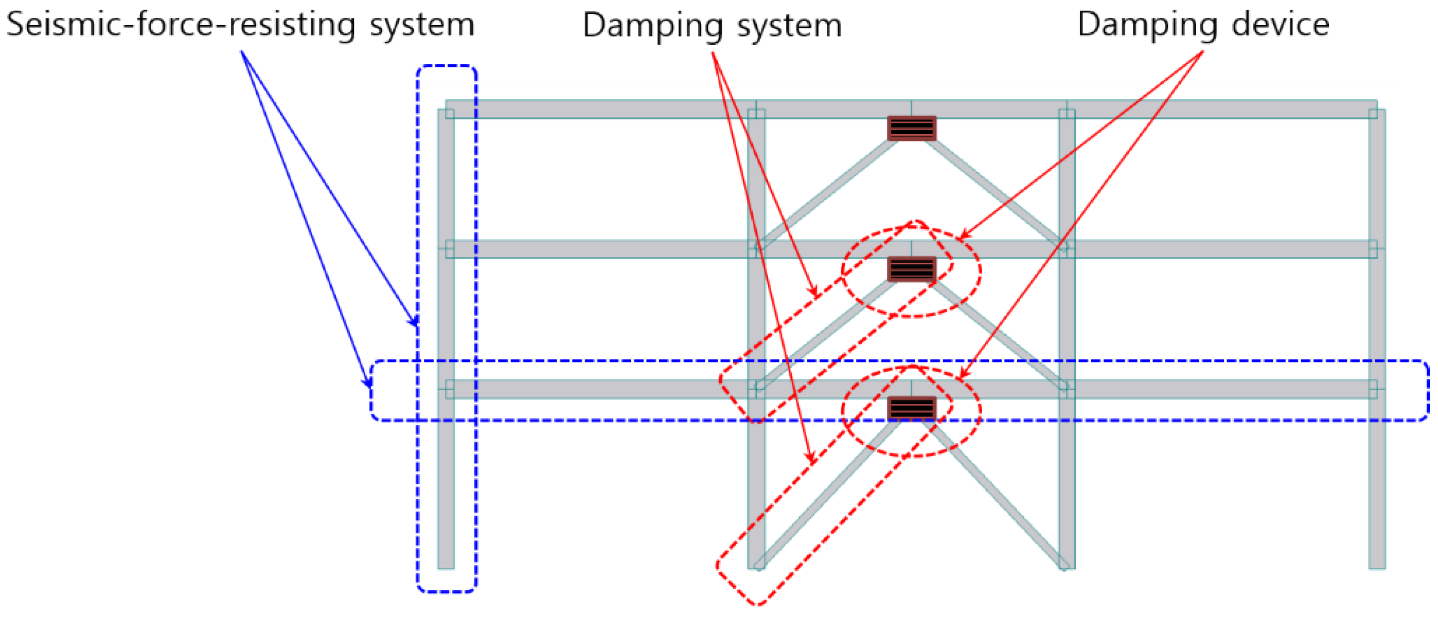
2.1. Damping Systems

The damping system is intended to reduce the seismic demand to a structure and refers to a subsystem that includes both damping devices and structural elements that transmit forces from the damping devices to seismic-force-resisting systems or foundations of the structure. The damping device is a structural element that dissipates energy by relative motion between two ends of the device and includes all the elements such as pins, bolts, gusset plates, braces, etc. necessary to install the damping device. The damping device may be installed in a separate structure out of the seismic-force-resisting system or in the seismic-force-resisting system. Figure 1 shows examples of configurations of damping devices and damping systems connected to a seismic-force-resisting system.
A damping device is classified into a velocity-dependent damping device whose force response depends on the relative velocity between the two ends of the device and a displacement-dependent damping device of which force response is determined by the relative displacement between the two ends of the devices. A mathematical model of the velocity-dependent damping system shall include the velocity coefficient corresponding to the test data. Displacement-response characteristics of the displacement-dependent damping device shall be modeled considering the dependence of seismic force response on the frequency, amplitude, and duration of ground motion clearly.
The components constituting the damping system shall be designed so that the damping device works normally without interruption. Thus, structural elements in the damping system are designed to remain elastic when subjected to design earthquake including forces transmitted from the damping device. The forces from the damping devices shall not be calibrated by the intensity reduction factor or the response correction factor. Moreover, the damping device shall be designed so as not to break when subjected to the maximum considered earthquake.

2.2. Seismic-Force-Resisting System

A building structure to which damping systems are applied shall have a seismic-force-resisting system defined in the KBC in each direction. Table 1 shows design factors of steel moment-resisting frame systems, which are appropriate to install damping devices due to relatively low stiffness and used in design examples of this study. At the initial stage, the seismic-force-resisting system of a building structure with damping systems are designed in order to resist the minimum base shear V m i n independently. V m i n is calculated by Equations (1) and (2).
V m i n = η V
η 0.75
where V is the design base shear calculated by equivalent lateral force procedure and η is the expected damping correction factor representing the degree of seismic force reduction acting on the structure obtained by damping systems. The expected damping correction factor η shall be validated through nonlinear response history analysis of the seismic-force-resisting systems combined with damping systems as described in the next section.

2.3. Damping Performance

The expected damping correction factor η applied to the minimum base shear V m i n of the seismic-force-resisting system shall be higher than or equal to the actual damping correction factor η h shown in Equation (3).
η h = V h V h e
where V h and V h e are the base shear calculated from the analysis of the structure with damping systems and from the analysis of the structure in which velocity-dependent components of damping devices are removed and displacement-dependent components of the damping devices are substituted into the effective stiffness, respectively.
The effective stiffness for the displacement-dependent component of the damping device is calculated based on the peak displacement and corresponding force of the damping device obtained from the analysis to calculate V h as follows.
k e f f = | F + | + | F | | Δ + | + | Δ |
where Δ + and Δ is the peak displacement of each damping device in positive and negative directions, respectively, and F + and F are corresponding forces, respectively.

3. Damping System Design Procedure

An efficient and systematic seismic design procedure for damping systems using nonlinear response history analysis is proposed in this section. The goal of the proposed procedure is to design structures with damping systems complying with the design requirements of KBC 2016 that does not specify a detailed design method.

3.1. Elastic Design of Seismic-Force-Resisting Systems

Seismic-force-resisting systems are designed to meet strength requirement for the minimum base shear with a target value of η . Then, the story drifts are checked using allowable story drifts corresponding to the seismic risk category. If some story drifts exceed the allowable story drifts, it is necessary to use damping systems in order to reduce the demand for those story drift. The allowable story drifts are 1.0%, 1.5%, and 2.0% for seismic risk category S, I, and II, respectively.

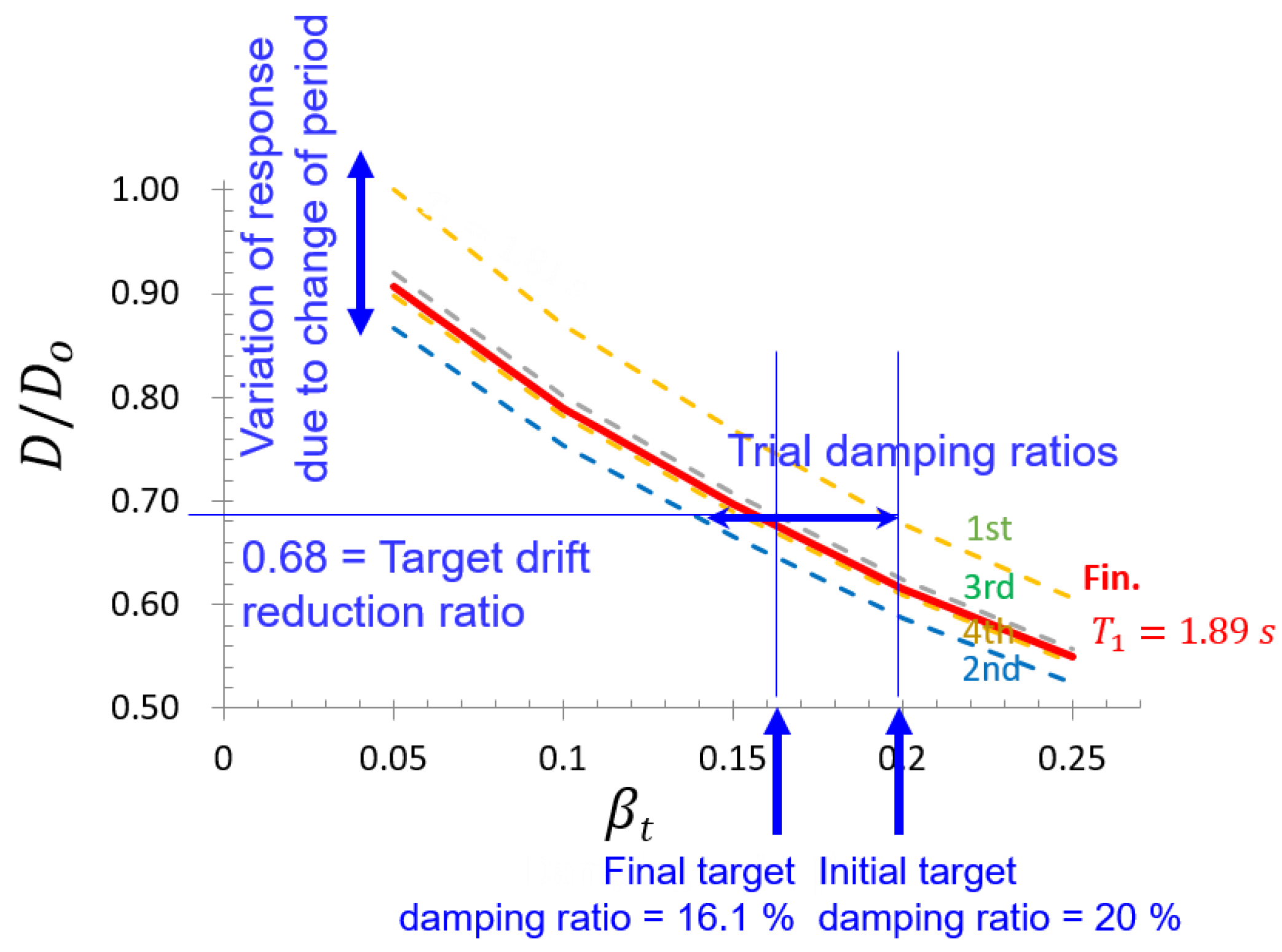
3.2. Target Damping Ratio Calculation

In order to estimate the target damping ratio, nonlinear response history analysis of the seismic-force-resisting system designed in Section 3.1 is performed repeatedly with a damping ratio raised at a constant increment. The peak story drift and peak base shear of the seismic-force-resisting systems are computed for each analysis until those peak responses reach their target values, respectively. Both peak story drift and peak base shear are determined as average responses obtained from nonlinear response history analysis using seven or more ground motion records. The target base shear V* is determined as the minimum base shear corrected by the demand‒capacity ratio (DCR), which is determined in the elastic design of the seismic-force-resisting system and represent redundancy in the design.
V * = V m i n D C R
The damping ratio of the seismic-force-resisting system is composed of inherent damping and damping added by damping systems. In this study, the damping ratio of the structure is assumed to be 5%. The target damping ratio β t is calculated by Equation (6).
β t = β I H + β v
where, β I H is the inherent damping ratio and β v is the damping ratio added by damping system. In the nonlinear response history analysis, β v is increased at a constant increment, and the increment need not be too small because the response can be interpolated numerically. Thus, three to five times of nonlinear response analysis for a given ground motion set is adequate.
Response reduction ratio with respect to effective damping ratio can be plotted in order to determine the target damping ratio and design of damping devices. An illustrative example of such plots is represented in Figure 2, where response reduction ratios for both base shear and maximum story drift are plotted in broken lines.

3.3. Damping Device Design

Damping device design is to determine design parameters that can provide damping parameters. Both displacement-dependent damping device and velocity-dependent damping device are addressed for illustrative design examples in this study. Metallic yielding dampers, friction dampers and many other types of dampers belong to displacement-dependent damping devices. The TADAS (triangular-plate added damping and added stiffness) system is adopted as an example of displacement-dependent damping devices in this study. Velocity-dependent damping devices include viscous dampers and viscoelastic dampers of which the latter provides a displacement-dependent force component. The viscoelastic damper is adopted as an example of velocity-dependent damping devices in this study.

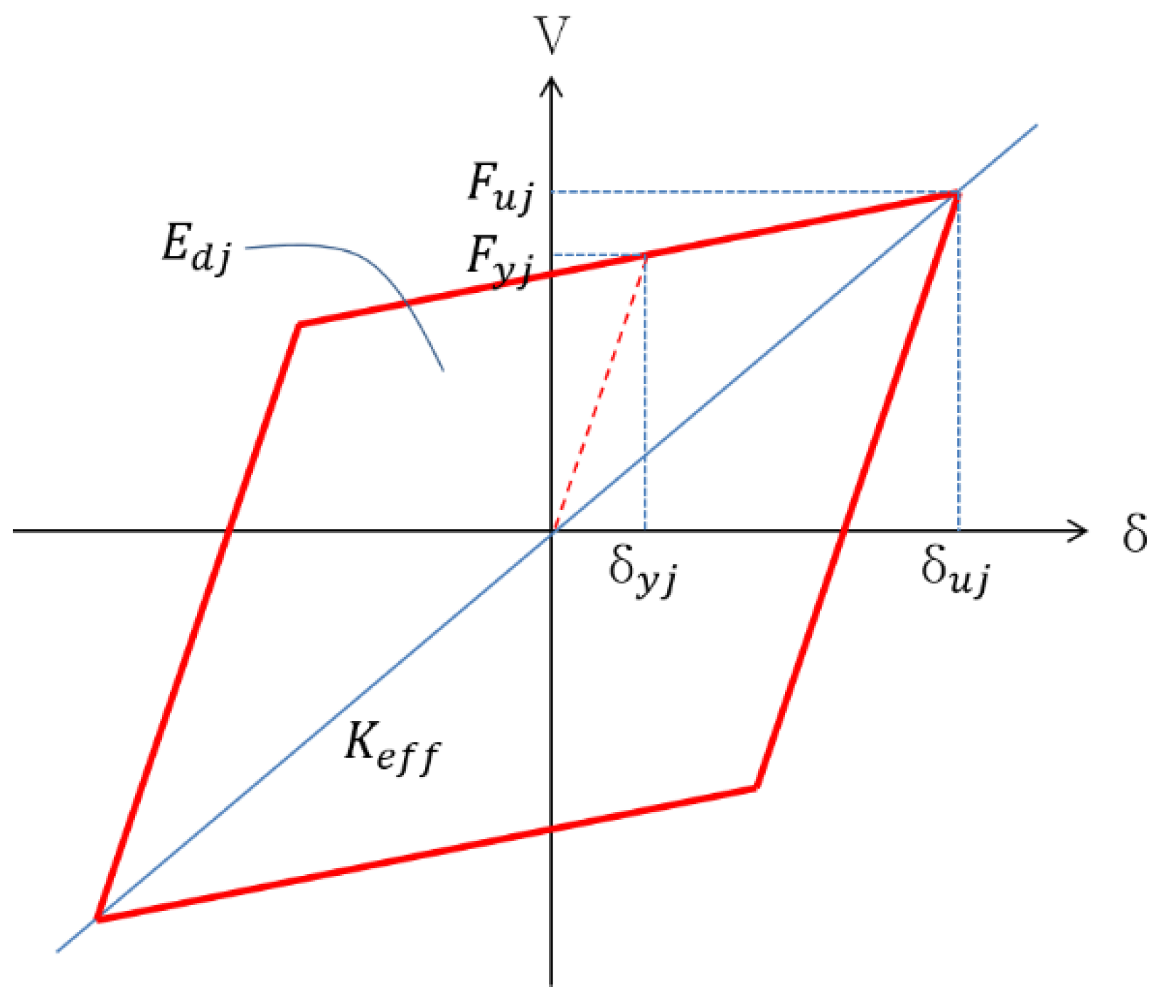
3.3.1. Effective Damping of Displacement-Dependent Damping Devices

The force-displacement relationship of the TADAS system is defined as a bi-linear model with a post-yield stiffness ratio of 0.02. The strength and stiffness characteristics of the TADAS system including deformation capacity are calculated by Equations (7) to (9) using metal plate dimensions and material strengths of which details can be found in Ramirez et al. [24].
δ y = 3 2 ( ε y h 2 t )
V y = F y b t 2 4 h
δ m a x = ε m a x h 2 t
where δ y , V y and δ m a x are yield deformation, yield strength and deformation capacity, respectively, and b , h and t are width, height and thickness of the triangular metal plate, ε y is the yield strain of the material, ε m a x is the strain limit of the damping device and can be calculated by the following equation [25,26,27,28].
ε m a x = A N f B
where N f is the number of deformation cycles and assumed to be 100, A and B are constant and assumed to be 0.08 and 0.3, respectively [24]. The peak deformation demand on the damping device is calculated as follows.
δ u = h i θ i
where θ i and h i are the peak story drift angle (rad) and the story height of the i-th story.
For given peak deformation demands, the effective damping ratio can be calculated by Equations (12) in accordance with ASCE 7-10 based on the energy dissipation due to cyclic deformations illustrated in Figure 3 [29].
β v = E d j 4 π E s
where E s is the strain energy stored in the structure E d j is the energy dissipated by the j-th damping device. E s and E d j are calculated by the following equations.
E s = 1 2 F i δ i
E d j = 4 ( F y j δ u j F u j δ y j )
where F i and δ i are the peak lateral force and peak lateral displacement at the i-th story, respectively, δ y j , δ u j , F y j and F u j are the yield displacement, peak displacement, yield strength and peak force of the i-th damping device.

3.3.2. Effective Damping of Velocity-Dependent Damping Devices

The characteristics of the viscoelastic damping device adopted in this study are based on the experimental results of Soong and Dargush (1997) represented in Table 2 [30]. Kelvin model illustrated in Figure 4 is adopted for numerical modeling of the viscoelastic damping device. Effective stiffness and damping coefficients of the model are given by the following equations
K d = A G t d
C d = η d ω K d
where G and η d are storage modulus and loss factor of the viscoelastic material, respectively, A and t d are the shear area and thickness of the viscoelastic damper, respectively, and ω is the excitation frequency, which is taken as the fundamental frequency of the structure with effective stiffness of damping devices. Added damping ratio β v can be calculated by the following equation on the basis of the modal strain energy method [31].
β v = η d 2 ( 1 ω n 2 ω ¯ n 2 )
where ω n and ω ¯ n are the natural frequency before and after installation of damping systems, respectively. Although the modal strain energy method is applicable to linear elastic structures, it is assumed that nonlinear damping devices is linearized using effective stiffness. Thus, ω ¯ n is calculated by eigenvalue analysis of the structure with the effective stiffness of damping systems added. The thickness of the viscoelastic damper t V E D can be calculated as follows.
t V E D = Δ u γ m a x
where Δ u is the maximum shear deformation of the damping device and γ m a x is the maximum strain capacity

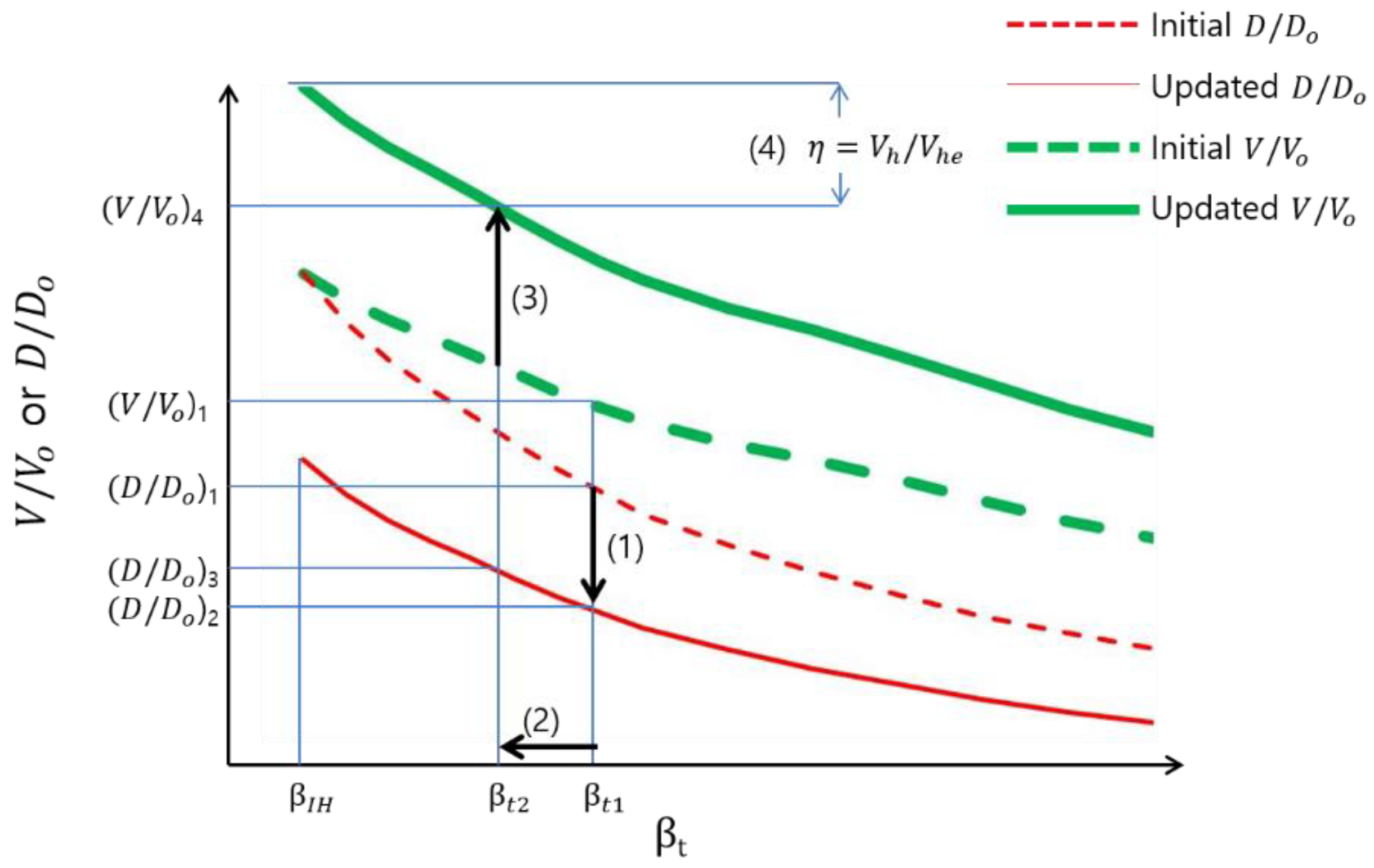
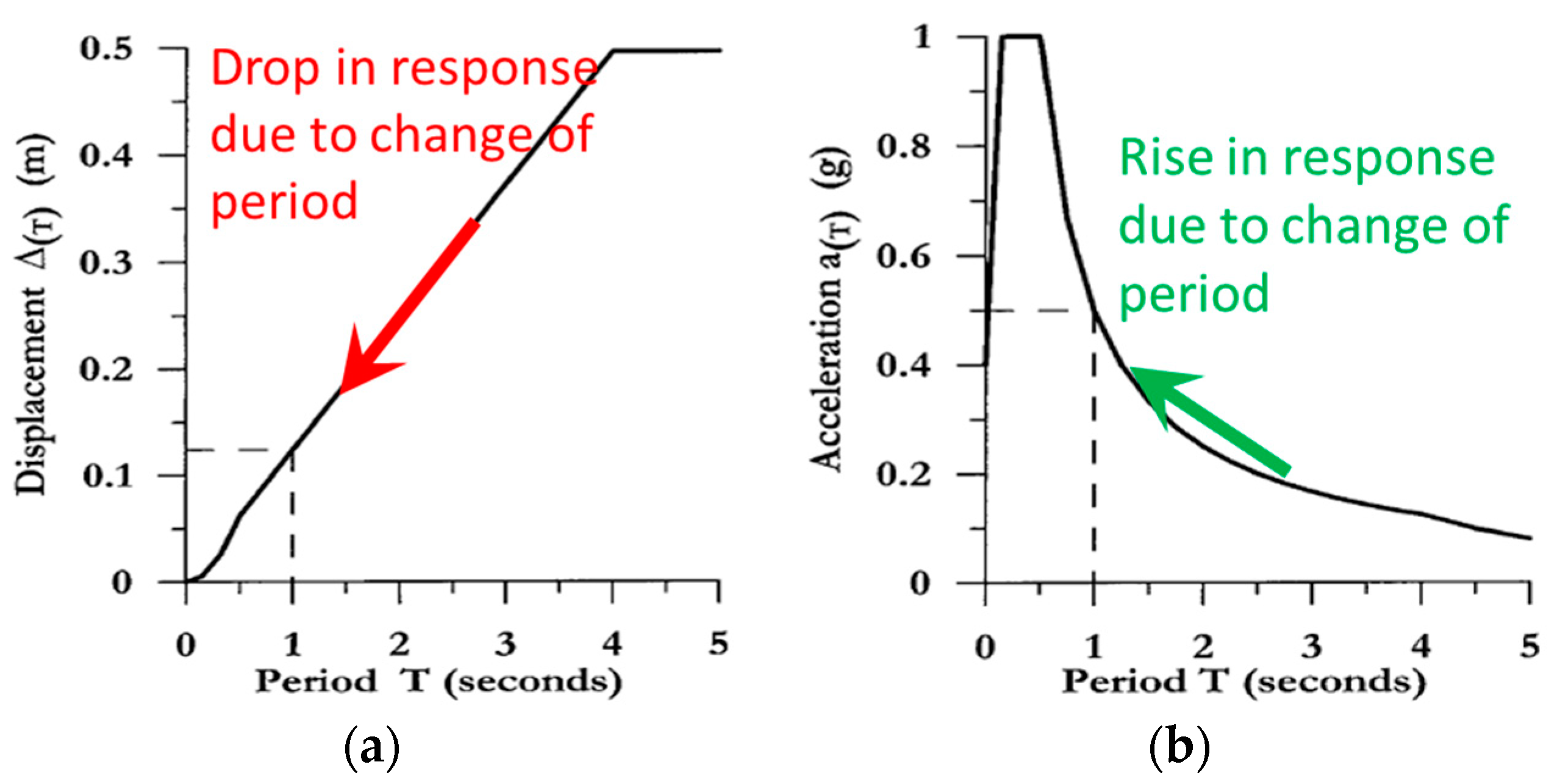
3.3.3. Design of Damping Devices Considering Change of the Natural Frequency

Once damping device properties are determined, it is necessary to update the effective damping ratio β v because the effective damping ratio β v given by Equations (12) or (17) is dependent on the stiffness and/or strength of the damping device. A rational method to update the effective damping ratio considering response reduction and stiffening effects of damping devices is described in this section and Figure 2 illustrates the procedure for updating the effective damping ratio conceptually.
(Step 1) Base shear and maximum story drift reduction factors are plotted with respect to β t , broken lines in Figure 2.
(Step 2) The target damping ratio β t 1 corresponding to the initial base shear reduction factor ( V / V o )1 is interpolated from the plot ‘Initial V / V o ’ (thick broken line) in Figure 2.
(Step 3) The maximum story drift reduction factor ( D / D o )1 is interpolated from the plot ‘Initial D / D o ’ (thin broken line) in Figure 2.
(Step 4) Damping devices are designed to achieve the target damping ratio Equation (12) or (17) subjected to deformations corresponding to ( D / D o )1. Those deformations can be approximated by multiplying ( D / D o )1 to the initial response for only β I H .
(Step 5) Effective stiffness of damping devices is calculated and added to the structure without damping devices. Then, the fundamental frequencies of the structure are updated.
(Step 6) Response reduction factors are updated corresponding to change of the fundamental frequencies. The peak story drift reduction factor is reduced on the basis of displacement design spectrum, as shown in Figure 5a due to fundamental period shortening. The modified peak story drift reduction factor is plotted as ‘Updated D / D o ’ (thin solid line) in Figure 2.
(Step 7) The effective damping ratio is updated to β t 2 considering the decrease of deformations in (Step 6), and corresponding maximum story drift reduction factor is interpolated from the plot ‘Updated D / D o ’ in Figure 2.
(Step 8) The base shear reduction factor is determined on the basis of pseudo-acceleration design spectrum and increased due to shortening of the fundamental period, as shown in Figure 5b. The modified base shear reduction factor is represented as ‘Updated V / V o ’ in Figure 2 (thick solid line).
(Step 9) Damping correction factor η for β t 2 is calculated as a ratio between V / V o ’s at β t 2 and β I H on ‘Updated V / V o ’ in Figure 2.
(Step 10) Adjust ( V / V o )1 and repeat (Step 2) to (Step 9) until η becomes sufficiently close to the target.
(Step 11) If η converges to the target, nonlinear response history analysis is performed in order to confirm whether the actual response reduction factor satisfies design requirements or not.
The design procedure proposed above utilizes nonlinear response history analysis only at Step 1. Additional response prediction is performed using the elastic design spectrum. Thus, the proposed design procedure is computationally efficient compared to the trial-and-error method based on fully nonlinear response history analysis.

4. Design Example

Two design examples based on the proposed damping system design procedure are presented. The first example is a three-story steel moment-resisting frames with metallic yielding dampers and the second example is a six-story steel moment-resisting frames with viscoelastic dampers.

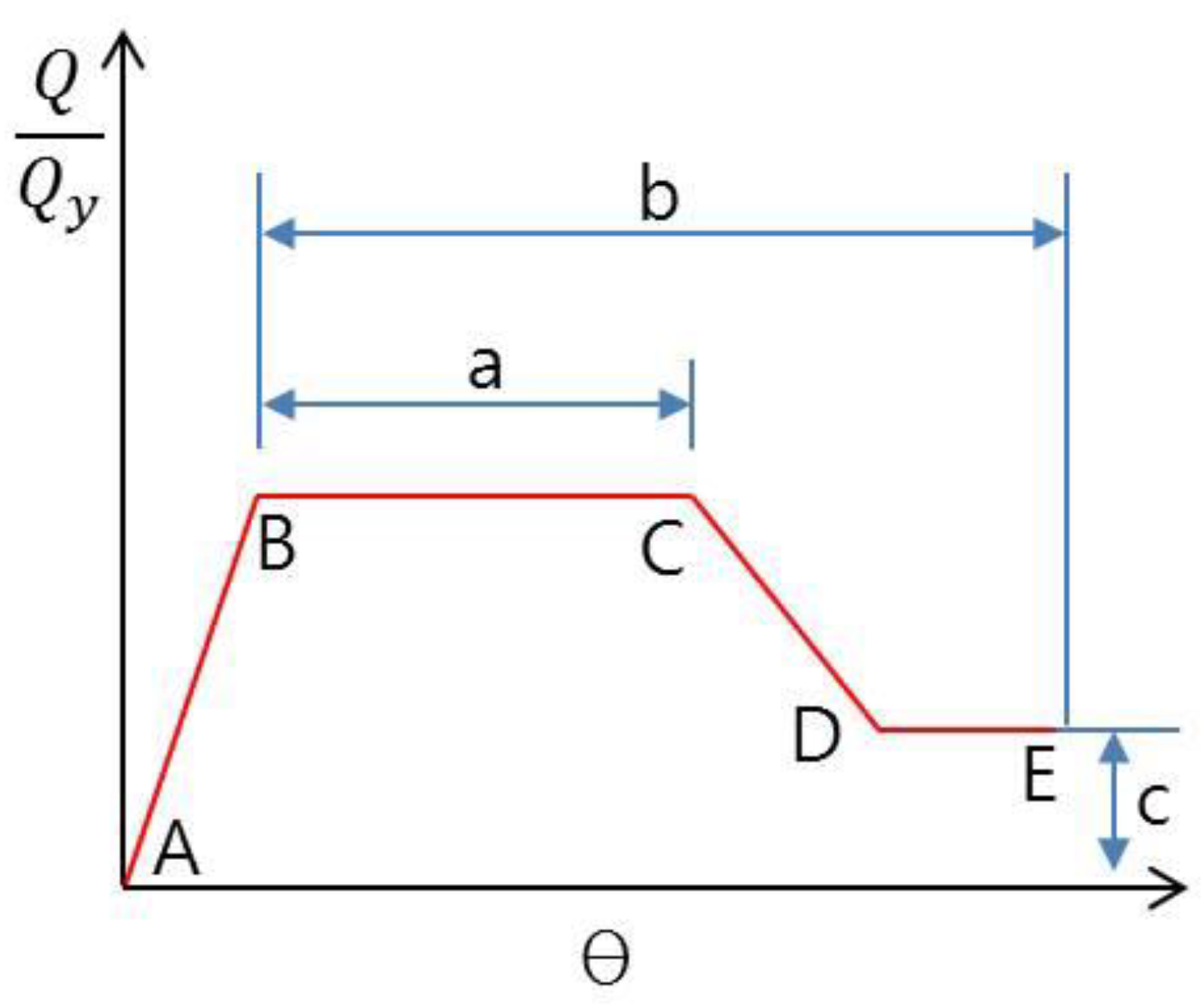
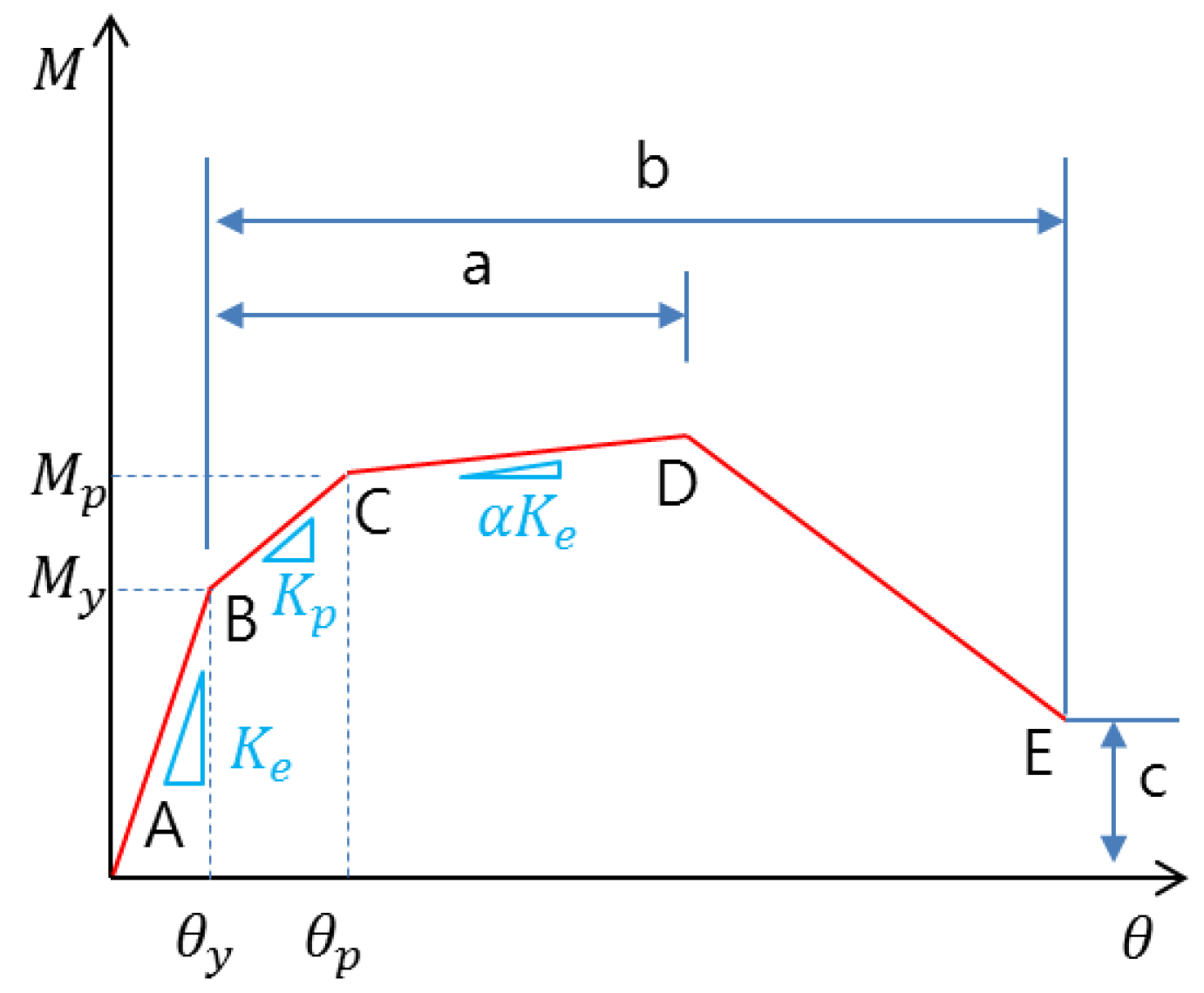
4.1. Nonlinear Modeling of Structural Elements

Nonlinear modeling of beams and columns of the steel moment frames is performed in accordance with ASCE 41-13 [32]. Common load-deformation relationship for beams and columns subjected to flexure is represented in Figure 6, where the yield rotation angle of beams and columns is calculated by Equations (19) and (20), respectively.
Beams :   θ y = Z F y l b 6 E I b
Columns :   θ y = Z F y l c 6 E I c ( 1 P P y e )
where l b , l c , Z and l are the moment of inertia for beams and columns, the plastic section modulus and member length, respectively. In addition, E , F y , P and P y e are the modulus of elasticity, yield strength of steel, the axial force acting on the member and the axial strength of member, respectively.
The panel zone of the steel moment frame was explicitly modeled with Krawinkler’s model [33] of which configuration is represented in Figure 7, and the load‒deformation relationship is shown in Figure 8. The characteristics of the panel zone model were calculated by the following Equations.
K e = 0.95 d b d c t p G
K p = 1.04 b f c t f c 2 G
M y = 0.55 F y t p 0.95 d b d c
θ p = 4 θ y
where d b , d c , b f c , t p , t f c , G and α are beam depth, column depth, column flange width, panel zone thickness, column flange thickness, shear modulus and strain-hardening ratio (0.02), respectively. Perform-3D software was used for modeling and nonlinear response history analysis.

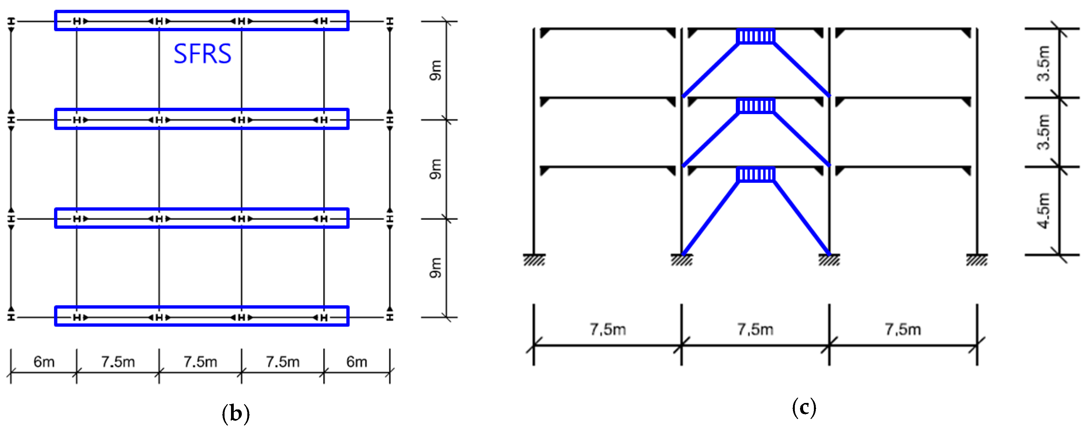
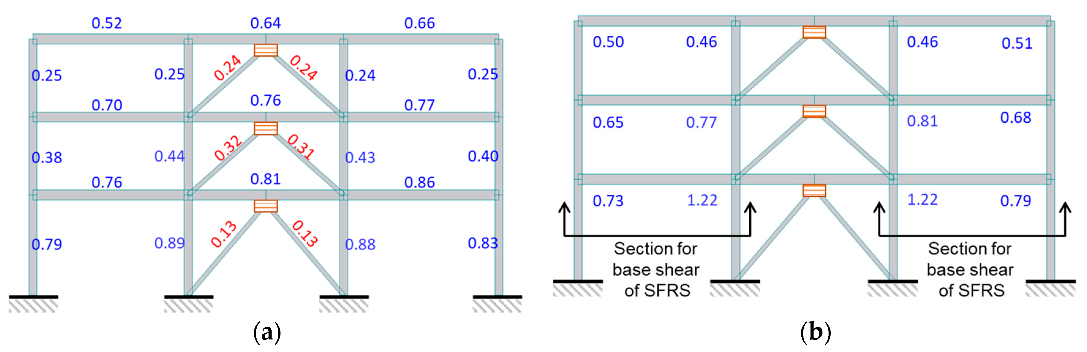
4.2. Three-Story Steel Moment-Resisting Frames with Metallic Yielding Dampers (3F-OMRF-MD)

4.2.1. Initial Design of Seismic-Force-Resisting System

An example building with displacement-dependent damping devices is designed based on the KBC 2016, which is composed of three stories, five spans in X direction, three spans in Y direction. Figure 9a,b shows a three-dimensional view and plan view of the building. All the X-directional internal frames are identical and only one frame is used in this design example and represented in Figure 9c. The dead and live loads of the structure applied to building floors are 5.0 kN/m2 and 3.5 kN/m2, respectively, and identical for all stories. The building is assumed to be located in seismic zones I and belong to seismic risk category ‘Special’. Site class SD is assumed for the building. The seismic-force-resisting system of the building is designed as an ordinary moment-resisting frame of which design factors are listed in Table 1. Allowable story drift of 1.0 % for seismic risk category ‘Special’ is adopted.
The initial design of the moment-resisting frame was performed for the minimum base shear with η = 0.75. The properties of columns and beams of the designed frame are listed in Table 3. The same section is used for each member in all stories. SM490 material was applied to all the members. The DCR of the initial design result is 0.95. Thus, the target base shear reduction factor required for damping systems is moderated to be 0.79, considering the DCR.
From linear dynamic analysis using the response spectrum method, the maximum story drift without damping devices was 1.32%, which occurs at the first story and is higher than the allowable story drift of 1.0%. Therefore, it is necessary to reduce the story drift as well as base shear using damping devices. TADAS damping devices are installed at the center span using brace members listed in Table 3. Thus, the center frame and the damping devices shown in Figure 9c comprises a damping system.

4.2.2. Design of Displacement-Dependent Damping Devices

In order to achieve target reduction factors for base shear and maximum story drift, those two response values are recorded from nonlinear response history analyses repeated with incremental damping of 0.05. Thus, the nonlinear response history analysis was performed only five times. Response reduction factors obtained from the nonlinear response history analysis are plotted in Figure 10.
Target damping ratio corresponding to the base shear reduction factor 0.79 is interpolated to be 19.1%. The damping devices were designed to achieve an added damping of 0.141 except 0.05 inherent damping of the moment-resisting frame. To design each damping device, the total dissipated energy E d j was calculated from Equation (12) in combination with Equation (13). Then E d j was distributed to each story in proportion to the story shear force. It is taken into account that yield strength or friction force of displacement-dependent damping devices are distributed based on the distribution of story shear force to maximize energy dissipation [34,35]. First estimation of target β v and corresponding β t were 0.141 and 0.191. Characteristics of damping devices determined to achieve the target β v on the basis of Equation (14) are given in Table 4. The post-yield stiffness ratio of the damping device was assumed to be 0.02 in the calculation of dissipated energy.
The fundamental period of the structure without damping devices was 1.04 sec. The fundamental period of the moment-resisting frame with damping devices substituted by secant stiffness thereof at respective peak deformations of them was reduced to 0.92 sec. Considering the change of the fundamental period, the story drift reduction factor was decreased, as shown in Figure 10. Then, β v and corresponding β t were modified into 0.12 and 0.17, respectively, using updated damping device deformations corresponding to the adjusted story drift reduction factor. As a result, the corresponding maximum story drift response is reduced to 64% compared to the structure with 0.05 damping ratio. Using those updated damping device deformations, the fundamental period based on the secant stiffness of damping devices was calculated to be 0.91 second. Then, the base shear reduction factor was elevated corresponding to 0.91 second period as shown in Figure 10. Finally, damping device yield strengths are modified in order to compensate reduced deformations due to period change and to achieve an added damping ratio β v of 0.12. The final damping device properties are listed in Table 4 for each story. Based on the modified base shear reduction factor represented by the thicker solid line in Figure 10, the expected damping correction factor is 0.93/1.14 = 0.82, which is slightly higher than the target η = 0.79. However, the damping performance obtained from the results of the nonlinear response history analysis is 0.79, which mean that the expected damping performance goal was achieved with a sufficiently accurate prediction of performance.
The average maximum story drift ratios for seven ground motion records representing design earthquake were 0.66%, 0.65% and 0.48% for the first, second, and third story, respectively, as summarized in Table 5 and all of those values are much smaller than the allowable story drift ratio 1.0%. This is because the base shear reduction factor 0.79 for seismic-force-resisting system governs the design rather than story drift reduction in this design example. The average maximum TADAS damping device deformation for seven ground motion records representing the maximum considered earthquake was maximum at the first story and calculated to be 41.2 mm. The deformation capacity of the example TADAS damping device is 60.3 mm. Therefore, damping devices can maintain the damping performance even under the maximum considered earthquake.
KBC 2016 requires structural elements comprising a damping system to remain elastic subjected to both seismic loads and forces induced by damping devices for design earthquake. DCRs for the frame members and panel zones were computed in terms of rotation angle ductility from nonlinear response history analysis and represented in Figure 11. In the case of columns and braces, higher DCR among bending moment DCR and axial force DCR in a member is given in Figure 11a. All the members that belong to the damping system at the central bay remain elastic since DCRs are lower than 1.0. Therefore, the design result obtained by the proposed procedure satisfies all the requirements of KBC 2016.
To examine the effect of structural steel material reduction by damping devices, a bare ordinary moment resisting frame is designed to achieve story drifts similar to the frame with damping devices. Steel sections and story drifts of two models with and without damping devices are summarized with the respective total weights in Table 5, where 3F-OMRF-SD represents the seismically designed bare frame. The total weight of steel sections for the frame with damping devices is 149 kN, which is 67% of 221 kN for the frame without damping devices. Thus, the proposed procedure can yield efficient structural material-saving design. Ramirez et al. [5] provide similar design example, in which three-story and three-bay frames are designed without and with metallic yielding damping devices using equivalent lateral force procedure although the seismic-force-resisting system is a special moment-resisting frame and target story drift ratio is set to 2% differently from this study. In the comparative design example, the frame with damping devices has 76% of the weight for frames without damping devices. In spite of several different conditions, this comparison supports the ability of the proposed design procedure to reduce seismic demand on the seismic-force-resisting system with supplementary energy dissipation relying on more accurate response prediction by nonlinear response history analysis.

4.3. Six-Story Steel Moment Frames with Viscoelastic Dampers (6F-SMRF-VED)

4.3.1. Initial Design of Seismic-Force-Resisting System

A six-story steel moment-resisting frame is designed in this example. Velocity-dependent damping devices are added for seismic response reduction. The steel moment frame has five spans in the longitudinal direction, and three spans in the transverse direction. The building is assumed to be located in Seismic zone I of KBC 2016 and belong to seismic risk category ‘Special’ of which importance factor is 1.5. Site class was assumed to be SD. The overall design was performed under conditions similar to the example building with displacement-dependent damping systems. However, a special moment-resisting frame was adopted for the seismic-force-resisting system. The numerical model of the example building is represented in Figure 12.
In the transverse direction, only two special moment-resisting frames placed at the outermost part of the building plan play a role of seismic-force-resisting system. Considering geometrical symmetry, only one moment-resisting frame is modeled in the example for simplicity. In addition, the P-Δ effect due to gravity loads at the center of the plan was taken into account using the leaning column as shown in Figure 12c.
The initial design of the special moment-resisting frame was performed for the minimum base shear with η = 1.0. The DCR of the initial design result is 0.88. Table 3 summarizes sections of members used in the designed frame. Since η assumed in the design equals 1.0, it is unnecessary to confirm whether a target base shear reduction factor is achieved. The damping devices are installed at the center span of the planar frame with braces and illustrated in Figure 12c. Thus, the frame in the central bay and the damping devices shown in Figure 12c comprises a damping system.
From linear dynamic analysis based on response spectrum method with response modification factor and deflection amplification factor defined in KBC 2016, it was observed that the highest peak story drift was 1.75% and observed in the third and fourth stories. It is necessary to reduce the story drift by the damping device because it does not satisfy the allowable story drift of 1.0%.

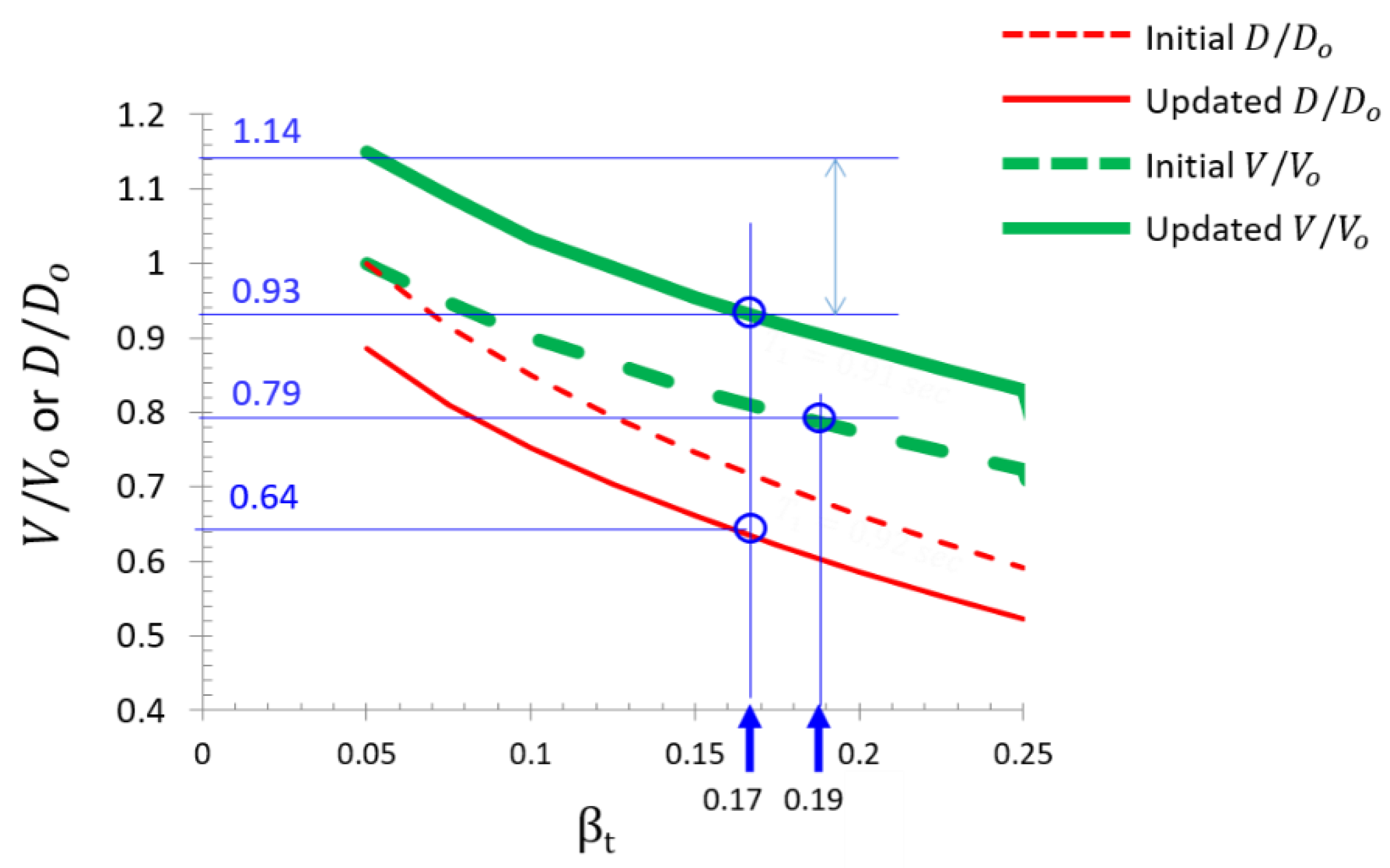
4.3.2. Design of Velocity-Dependent Damping Devices

The natural frequency of the first mode was 0.5 Hz from the eigenvalue analysis of the structure with only the stiffness component of the viscoelastic damping devices. Viscoelastic damper characteristics corresponding to an excitation frequency of 1.0 Hz, which is the closest one to 0.5 Hz, was adopted among those dependent on excitation frequencies. The stiffness and damping coefficients of each damping device were calculated using Equation (15) and (16).
The average maximum story drift ratios from nonlinear response history analysis for seven ground motion records representing design earthquake are listed in Table 6. The maximum story drift ratio is found to be 1.48% for the third story. Target story drift reduction factor is 1.0%/1.48% = 0.68. The maximum story drift reduction factor was obtained from the nonlinear response history analysis of the moment-resisting frame with an incremental damping ratio of 0.05 that substitute damping devices. Thus, the nonlinear response history analysis was performed only five times and the maximum story drift reduction factor was plotted in Figure 13 and the target damping ratio β t interpolated from the plot is 0.20. To achieve the target damping ratio, β v = 0.15 excluding β I H = 0.05 is necessary to be added by damping devices.
The damping ratio added by viscoelastic damping devices is calculated by Equation (17), in which the added damping ratio is dependent on the fundamental frequency of the structure with effective stiffness of damping devices. In order to design damping devices, the stiffness K d of damping devices represented by Kelvin model are increased until the fundamental frequency becomes the target value corresponding to the target damping ratio. This work is conducted by eigenvalue analysis of the linear elastic model and does not require additional nonlinear response history analysis. The same stiffness was applied to all the damping devices in this design example, but more efficient distribution may be investigated [18]. When K d is determined, a corresponding C d can be calculated using Equation (16).
However, change of the fundamental frequency due to damping devices affects the maximum story drift reduction factor. As a result, the maximum story drift reduction factor in Figure 13 is updated repeatedly. For each update of the maximum story drift reduction factor, the target damping ratio changes correspondingly. Four times of update were performed and updated parameters including target damping ratios and target frequencies are summarized in Table 7. The final fundamental frequency converged to 1.89 sec and K a and C d reached 6800 kN/m and 2718 kN∙sec/m, respectively.
Nonlinear response history analysis was performed using the final stiffness and damping coefficient of the damping devices. It is unnecessary to examine design base shear because the damping correction factor was set to 1.0. The base shear reduction factor was 0.92 which is smaller than 1.0. The peak story drifts of the final design are summarized in Table 8. Compared to Table 6, the maximum peak story drift was reduced to 0.90%, which is slightly lower than the allowable story drift ratio of 1.0%. As a result, the proposed design methodology can design damping systems with a sufficiently accurate prediction of performance.
As with the displacement-dependent damping system design, the structural elements comprising the damping system must be both elastic against the loads including seismic loads and forces induced by damping devices for design earthquake. Braces to install damping devices transmitting damping device force to the seismic-force-resisting force and the column at the right-hand side of the first story damping device transmitting vertical component of damping device force to the foundation comprises the damping system of the structure. DCRs for the frame members and panel zones were computed in terms of rotation angle ductility from nonlinear response history analysis for design earthquake and represented in Figure 14. In the case of columns and braces, higher DCR between bending moment DCR and axial force DCR is given in Figure 14a. All the members that belong to the damping system in the central bay remain elastic with DCRs lower than 1.0.
Finally, damping device safety subjected to the maximum considered earthquake was checked. The maximum shear strain of damping devices was 0.455 from the response analysis for the maximum considered earthquake. The experimental data of Soong and Dargush used in the design of the damping device does not provide the deformation capacity of the damping device [20]. Therefore, it is necessary to ensure whether or not the damping device is broken for the strain demand subjected to the maximum considered earthquake. Therefore, the design result satisfies all the requirements of KBC 2016 under the premise that the deformation capacity requirement for the damping device can be met.
Like the three-story frame example, a bare special moment-resisting frame is designed to achieve story drifts similar to the frame with damping devices. Steel sections and story drifts of two models with and without damping devices are summarized with the respective total weights in Table 8 where 6F-SMRF-SD represents the seismically designed bare frame. The total weight of steel sections for the frame with damping devices is 297 kN, which is about 50% of 590 kN for the frame without damping devices. Thus, the proposed procedure can yield efficient structural material-saving design in case of viscoelastic damping devices. Ramirez et al. [5] provide similar design example, in which six-story and three-bay frames are designed without and with viscous damping devices using equivalent lateral force procedure although the damping device does not have stiffness component and target story drift ratio is set to 2% differently from this study. In the comparative design example, the frame with damping devices has 60% of the weight for frames without damping devices. Similar to the preceding design example, the proposed design procedure can design damping devices effectively to reduce seismic demand on the seismic-force-resisting system with better efficiency, which is owing to more accurate response prediction by nonlinear response history analysis.

5. Conclusions

This study proposed an efficient seismic design procedure for building structures with damping systems subjected to requirements of the revised Korean building code, KBC 2016, using nonlinear response history analysis. The proposed design procedure was validated by two design examples of steel moment-resisting frame with metallic yielding dampers and viscoelastic dampers, respectively. The conclusions from this study are summarized as follows.
  • The proposed design procedure makes use of nonlinear response history analysis, but does not repeat time-consuming nonlinear response history analysis until convergence of design solution. Instead, design parameters of damping devices are determined using the response reduction curve prescribed by a limited number of response history analyses. Only five times of response history analysis is sufficient for practical application.
  • The proposed design procedure can predict seismic response of nonlinear structures with considerable accuracy because basic response reduction factors are obtained through nonlinear response history although equivalent linearization technique is used partially to estimate effects of damping devices with limited computational efforts.
  • The proposed design procedure does not require an optimization procedure and can be conducted using commercial structural analysis software. However, the proposed design procedure provides a systematic process to update the design parameters of damping devices and converges to a final design meeting design goals.
  • The proposed design procedure for structures with damping systems can reduce structural materials of seismic-force-resisting systems efficiently by 30 to 50% compared to those without damping systems as illustrated by design examples for steel moment-resisting frames.

Author Contributions

Formal analysis, S.-H.J.; writing—original draft, J.-H.P.; writing—review & editing, T.-W.H.

Acknowledgments

This work was supported by Incheon National University Research Grant in 2016.

Conflicts of Interest

The authors declare no conflict of interest.

References

  1. Architectural Institute of Korea. AIK Korean Building Code. KBC 2009; AIK: Seoul, Korea, 2009. [Google Scholar]
  2. Architectural Institute of Korea. AIK Korean Building Code. KBC 2016; AIK: Seoul, Korea, 2016. [Google Scholar]
  3. American Society of Civil Engineers, Structural Engineering Institute. ASCE/SEI 7-16. Minimum Design Loads for Buildings and Other Structures; ASCE: Reston, VA, USA, 2016. [Google Scholar]
  4. Lin, Y.Y.; Tsai, M.H.; Whang, J.S.; Chang, K.C. Direct displacement-based design for building with passive energy dissipation systems. Eng. Struct. 2003, 25, 25–37. [Google Scholar] [CrossRef]
  5. Ramirez, O.M.; Constantinou, M.C.; Whittaker, A.S.; Kircher, C.A.; Johnson, M.W.; Chrysostomou, C.Z. Validation of the 2000 NEHRP provisions’ equivalent lateral force and modal analysis procedures for buildings with damping systems. Earthq. Spectra 2003, 19, 981–999. [Google Scholar] [CrossRef]
  6. Whittaker, A.S.; Constantinou, M.C.; Ramirez, O.M.; Johnson, M.W.; Chrysostomou, C.Z. Equivalent lateral force and modal analysis procedures of the 2000 NEHRP provisions for buildings with damping systems. Earthq. Spectra 2003, 19, 959–980. [Google Scholar] [CrossRef]
  7. Lin, Y.Y.; Chang, K.C.; Chen, C.Y. Direct displacement-based design for seismic retrofit of existing buildings using nonlinear viscous dampers. Bull. Earthq. Eng. 2008, 6, 535–552. [Google Scholar] [CrossRef]
  8. Silvestri, S.; Gasparini, G.; Trombetti, T. A five-step procedure for the dimensioning of viscous dampers to be inserted in building structures. J. Earthq. Eng. 2010, 14, 417–447. [Google Scholar] [CrossRef]
  9. Sullivan, T.J.; Lago, A. Towards a simplified direct DBD procedure for the seismic design of moment resisting frames with viscous dampers. Eng. Struct. 2012, 35, 140–148. [Google Scholar] [CrossRef]
  10. Palermo, M.; Silvestri, S.; Landi, L.; Gasparini, G.; Trombetti, T. A “direct five-step procedure” for the preliminary seismic design of buildings with added viscous dampers. Eng. Struct. 2018, 173, 933–950. [Google Scholar] [CrossRef]
  11. Kim, J.K.; Choi, H.H.; Min, K.W. Performance-based design of added viscous dampers using capacity spectrum method. J. Earthq. Eng. 2003, 7, 1–24. [Google Scholar] [CrossRef]
  12. Lin, Y.Y.; Chang, K.C. An improved capacity spectrum method for ATC-40. Earthq. Eng. Struct. Dyn. 2003, 32, 2013–2025. [Google Scholar] [CrossRef]
  13. Ramirez, O.M.; Constantinou, M.C.; Gomez, J.D.; Whittaker, A.S.; Chrysostomou, C.Z. Evaluation of simplified methods of analysis of yielding structures with damping systems. Earthq. Spectra 2002, 18, 501–530. [Google Scholar] [CrossRef]
  14. Park, J.-H. Seismic response of SDOF systems representing masonry-infilled RC frames with damping systems. Eng. Struct. 2013, 56, 1735–1750. [Google Scholar] [CrossRef]
  15. Chae, Y.; Ricles, J.M.; Sause, R. Development of equivalent linear systems for single-degree-of-freedom structures with magneto-rheological dampers for seismic design application. J. Intell. Mater. Syst. Struct. 2017, 28, 2675–2687. [Google Scholar] [CrossRef]
  16. Newmark, N.M.; Hall, W.J. Earthquake Spectra and Design; Earthquake Engineering Research Institute: Berkeley, CA, USA, 1982; pp. 35–36. [Google Scholar]
  17. Priestley, M.J.N.; Calvi, G.M.; Kowalsky, M.J. Displacement-Based Seismic Design of Structures; IUSS Press: Pavia, Italy, 2007. [Google Scholar]
  18. Park, J.-H.; Kim, J.; Min, K.-W. Optimal design of added viscoelastic dampers and supporting braces. Earthq. Eng. Struct. Dyn. 2004, 33, 465–484. [Google Scholar] [CrossRef]
  19. De Domenico, D.; Ricciardi, G. Earthquake protection of structures with nonlinear viscous dampers optimized through an energy-based stochastic approach. Eng. Struct. 2019, 179, 523–539. [Google Scholar] [CrossRef]
  20. Ontiveros-Perez, S.P.; Miguel, L.F.F.; Riera, J.D. Reliability-based optimum design of passive friction dampers in buildings in seismic regions. Eng. Struct. 2019, 190, 276–284. [Google Scholar] [CrossRef]
  21. Lavan, O.; Levy, R. Optimal design of supplemental viscous dampers for irregular shear-frames in the presence of yielding. Earthq. Eng. Struct. Dyn. 2005, 34, 889–907. [Google Scholar] [CrossRef]
  22. Lavan, O. A methodology for the integrated seismic design of nonlinear buildings with supplemental damping. Struct. Control Health Monit. 2015, 22, 484–499. [Google Scholar] [CrossRef]
  23. Wang, S.; Mahin, S.A. High-performance computer-aided optimization of viscous dampers for improving the seismic performance of a tall building. Soil Dyn. Earthq. Eng. 2018, 113, 454–461. [Google Scholar] [CrossRef]
  24. Ramirez, O.M.; Constantinou, M.C.; Kircher, C.A.; Whittaker, A.S.; Johnson, M.W.; Gomez, J.D.; Chrysostomou, C.Z. Development and Evaluation of Simplified Procedures for the Analysis and Design of Buildings with Passive Energy Dissipation Systems; Technical Report MCEER-00-0010; Multidisciplinary Center for Earthquake Engineering Research, University at Buffalo: Buffalo, NY, USA, 2000. [Google Scholar]
  25. Manson, S.S. Behavior of Materials under Conditions of Thermal Stress. In Heat Transfer Symposium; Engineering Research Institute, University of Michigan: Ann Arbor, MI, USA, 1953; pp. 9–75. [Google Scholar]
  26. Coffin, L.F., Jr. A Study of Effects of Cyclic Thermal Stresses on a Ductile Metal. Trans. Am. Soc. Mech. Eng. N. Y. 1954, 76, 931–950. [Google Scholar]
  27. Koh, S.K.; Stephens, R.I. Mean Stress Effects on Low Cycle Fatigue for High Strength Steel. Fatigue Fract. Eng. Mater. Struct. 1991, 14, 413–428. [Google Scholar] [CrossRef]
  28. Mander, J.R.; Panthaki, F.D.; Kasalanati, A. Low-Cycle Fatigue Behavior of Reinforcing Steel. J. Mater. Civ. Eng. 1994, 6, 453–467. [Google Scholar] [CrossRef]
  29. American Society of Civil Engineers, Structural Engineering Institute. ASCE/SEI 7-10. Minimum Design Loads for Buildings and Other Structures; ASCE: Reston, VA, USA, 2010. [Google Scholar]
  30. Soong, T.T.; Dargush, G.F. Passive Energy Dissipation Systems in Structural Engineering; John Wiley & Sons Ltd.: London, UK; New York, NY, USA, 1997. [Google Scholar]
  31. Chang, K.C.; Lai, M.L.; Soong, T.T.; Hao, D.S.; Yeh, Y.C. Seismic Behavior and Design Guidelines for Steel Frame Structures with Added Viscoelastic Dampers; Technical Report MCEER-93-0009; Multidisciplinary Center for Earthquake Engineering Research, University at Buffalo: Buffalo, NY, USA, 1993. [Google Scholar]
  32. Pekelnicky, R.; Engineers, S.D.; Chris Poland, S.E.; Engineers, N.D. ASCE 41-13: Seismic Evaluation and Retrofit Rehabilitation of Existing Buildings. In Proceedings of the SEAOC 2012 Convention, Santa Fe, NM, USA, 12–15 September 2012. [Google Scholar]
  33. Krawinkler, H. Shear in beam-column joints in seismic design of steel frames. Eng. J. 1978, 15, 82–91. [Google Scholar]
  34. Lee, S.-H.; Park, J.-H.; Lee, S.-K.; Min, K.-W. Allocation and slip load of friction dampers for a seismically excited building structure based on storey shear force distribution. Eng. Struct. 2008, 30, 930–940. [Google Scholar] [CrossRef]
  35. Nabid, N.; Hajirasouliha, I.; Petkovski, M. A Practical Method for Optimum Seismic Design of Friction Wall Dampers. Earthq. Spectra 2017, 33, 1033–1052. [Google Scholar] [CrossRef] [Green Version]
Figure 1. Damping system (DS) and seismic-force-resisting system (SFRS) configurations.
Applsci 09 02317 g001
Figure 2. Design process of damping device.
Applsci 09 02317 g002
Figure 3. Energy dissipation of metallic damping device.
Applsci 09 02317 g003
Figure 4. Kelvin model of viscoelastic damping devices.
Applsci 09 02317 g004
Figure 5. Modification of response due to change of the fundamental period: (a) Displacement spectrum and (b) pseudo-acceleration spectrum.
Applsci 09 02317 g005
Figure 6. Load‒deformation relationship of beams and columns [12].
Applsci 09 02317 g006
Figure 7. Krawinkler’s model for panel zone.
Applsci 09 02317 g007
Figure 8. Load‒deformation relationship for panel zone [22].
Applsci 09 02317 g008
Figure 9. Three-story steel moment resisting frame with metallic yielding dampers: (a) Isometric view, (b) plan, (c) elevation of internal frame.
Applsci 09 02317 g009aApplsci 09 02317 g009b
Figure 10. Base shear and peak story drift reduction factors.
Applsci 09 02317 g010
Figure 11. Demand–capacity ratio (DCR) of three-story steel moment-resisting frames with metallic yielding dampers (3F-OMF-MD): (a) Frame members, (b) panel zones.
Applsci 09 02317 g011
Figure 12. Six-story steel moment-resisting frames with viscoelastic damping devices: (a) Isometric view, (b) plan, (c) elevation of internal frame for design example.
Applsci 09 02317 g012
Figure 13. Normalized response vs. incremental damping ratios.
Applsci 09 02317 g013
Figure 14. DCR of 6F-SMRF-VED. (a) Frame members, (b) panel zones.
Applsci 09 02317 g014
Table 1. Design factors for steel moment-resisting frame systems.
Steel Moment-Resisting Frame
Systems
Design Coefficients
Response
Modification
Factor
R
Overstrength
Factor
Ω o
Deflection
Amplification
Factor
C d
Special835.5
Intermediate4.534
Ordinary3.533
Table 2. Properties of the viscoelastic damping device [20].
Temperature
(°C)
Frequency
(Hz)
Strain
(%)
Shear Storage
modulus ,   G
(MPa)
Shear loss
modulus ,   G
(MPa)
Loss
Factor
η d
241.0200.9581.1511.20
Table 3. Properties of moment-resisting frames.
ModelMemberStorySectionMaterial
3F-OMRF-MDBeam1‒3H-506 × 201 × 11/19SM490
f y = 315 MPa
f u = 490 MPa
Column1‒3H-394 × 405 × 18/18
Brace1‒3H-200 × 200 × 8/12
6F-SMRF-VEDBeam5‒6H-354 × 176 × 8/13
3‒4H-450 × 200 × 9/14
1‒2H-496 × 199 × 9/14
Column4‒6H-414 × 405 × 18/28
1‒3H-428 × 407 × 20/35
Brace1‒6H-244 × 252 × 11/11
Table 4. Characteristics of TADAS damping devices to achieve target damping ratio.
β v FloorStory Force
Ratio
V y
(kN)
V u
(kN)
δ y
(mm)
δ u
(mm)
0.14130.561401474.617.2
20.822042234.624.8
11.002492705.930.4
0.12030.571451524.615.7
20.812092264.622.6
11.002552745.928.2
Table 5. Comparison of drift ratio and structural weight.
Seismic Design ModelStoryStory Drift Ratio (%)Member Section (DCR)Weight (kN)
3F-OMRF-MD
(with damping devices)
30.48Beam: H-506 × 201 × 11/19 (0.79)
Column: H-394 × 405 × 18/18 (0.81)
Brace: H-200 × 200 × 8/12 (0.29)
149
20.65
10.66
3F-OMRF-SD
(without damping devices)
30.39Beam: H-692 × 300 × 13/20 (0.57)
Column: H-428 × 407 × 20/35 (0.58)
221
20.59
10.61
Table 6. Peak story drifts of six-story steel moment frames with viscoelastic dampers (6F-SMRF-VED).
Seismic Risk CategoryImportance FactorStoryStory-Drift Ratio without Damping Devices (%)Allowable Story-Drift Ratio (%)
Equivalent Static AnalysisNonlinear Response History Analysis
S1.561.321.241.00
51.591.28
41.751.31
31.751.48
21.541.39
10.930.76
Table 7. Target damping ratio and frequency.
Structure without Damping DevicesIterationTarget Damping Ratio
β t
Added Damping Ratio
β v
Target Frequency
ω ¯ (rad/sec)
Target Period
T ¯ (sec)
Fundamental Period
T (sec)
Fundamental Frequency
ω (rad/sec)
2.093.00-0.0500.0003.002.09
1st0.2000.1503.471.81
2nd0.1420.0923.261.93
3rd0.1660.1163.341.88
4th0.1560.1063.311.90
Fin0.1610.1113.331.89
Table 8. Comparison of peak drift ratio and structural weight.
Seismic Design ModelStoryStory Drift
(%)
Member Section (DCR)Weight (kN)
BeamColumn or Brace
6F-SMRF-VED
(with damping systems)
60.51H-354 × 176 × 8/13
(0.75)
Column: H-414 × 405 × 18/28 (0.19)
Brace: H-244 × 252 × 11/11 (0.43)
297
50.68
40.83H-450 × 200 × 9/14
(0.79)
30.90Column: H-414 × 405 × 18/28 (0.32)
Brace: H-244 × 252 × 11/11 (0.46)
20.85H-496 × 199 × 9/14
(0.78)
10.51
6F-SMRF-SD
(without damping systems)
60.62H-506 × 201 × 11/19
(0.36)
Column: H-498 × 432 × 45/70 (0.07)590
50.77
40.90H-606 × 201 × 12/20
(0.47)
30.97Column: H-498 × 432 × 45/70 (0.15)
20.88H-606 × 201 × 12/20
(0.45)
10.48

