Hydrogen Fuel Cell Vehicles; Current Status and Future Prospect


 and
and
Abstract
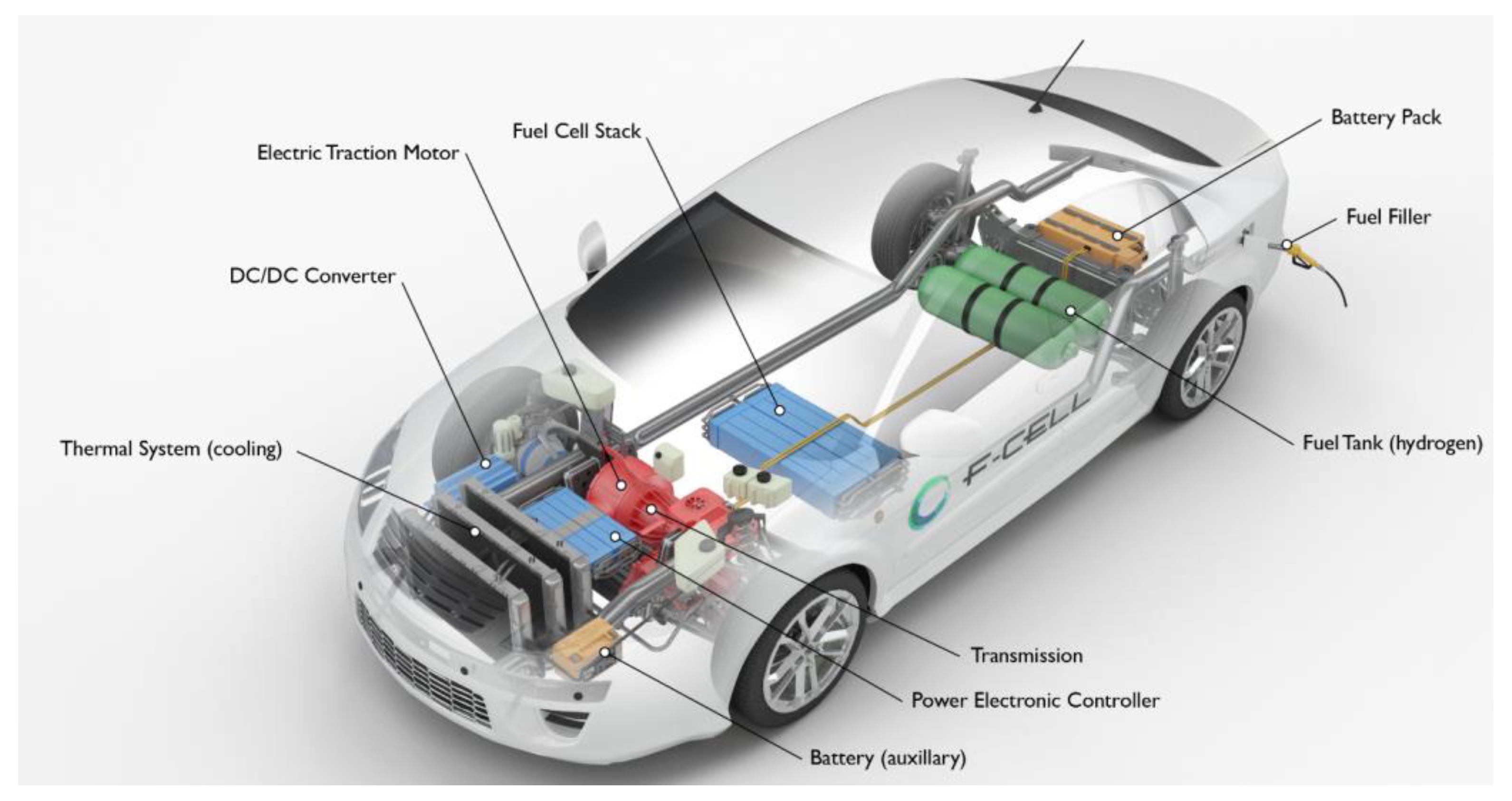
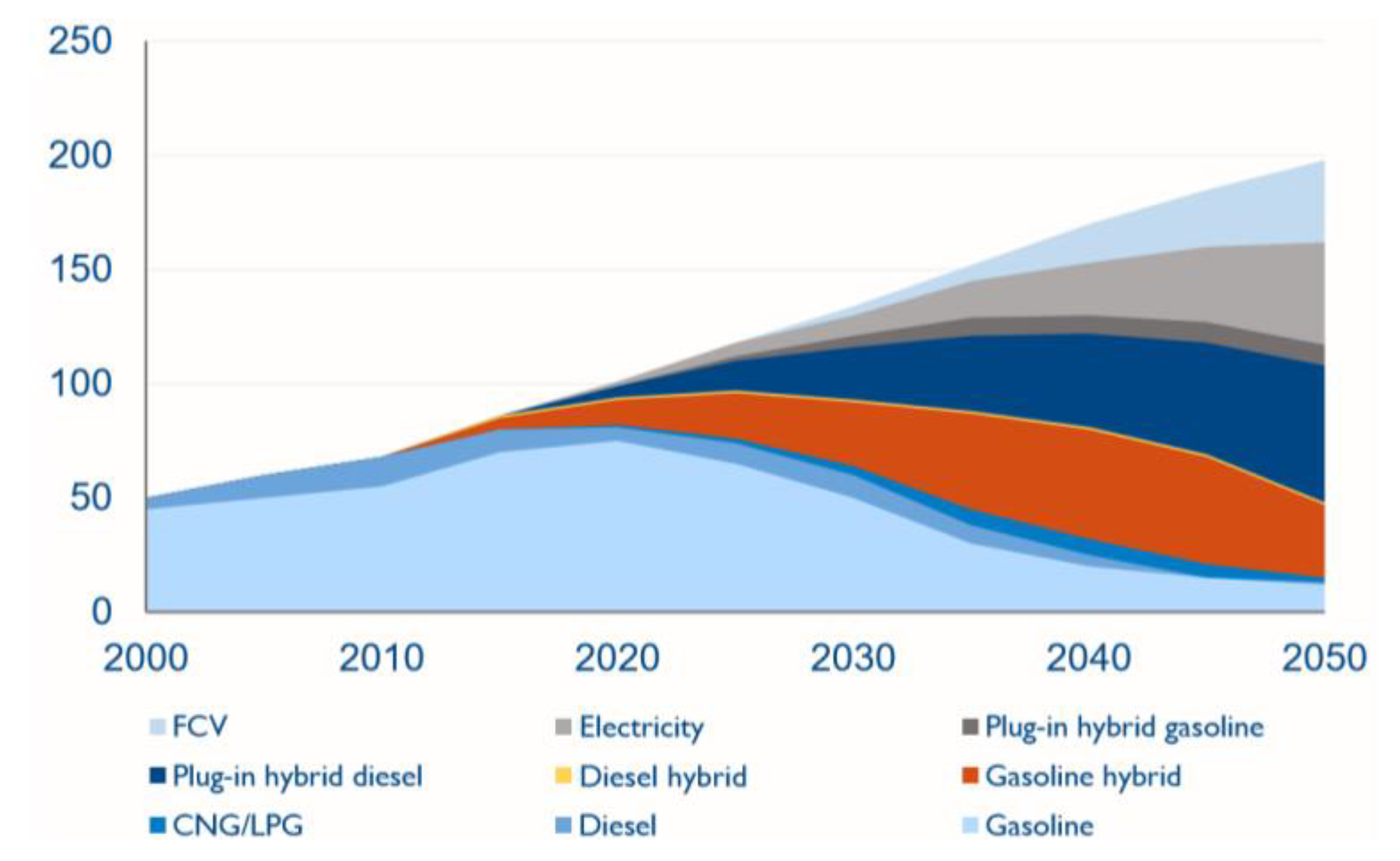
1. Introduction
2. Hydrogen as a Transportation Fuel
3. Hydrogen Storage in FCVs
3.1. Pressurized Tank Storage
3.2. Hydrogen Uptake in Metal-Based Compounds
3.3. Cryogenic Liquid Hydrogen Storage
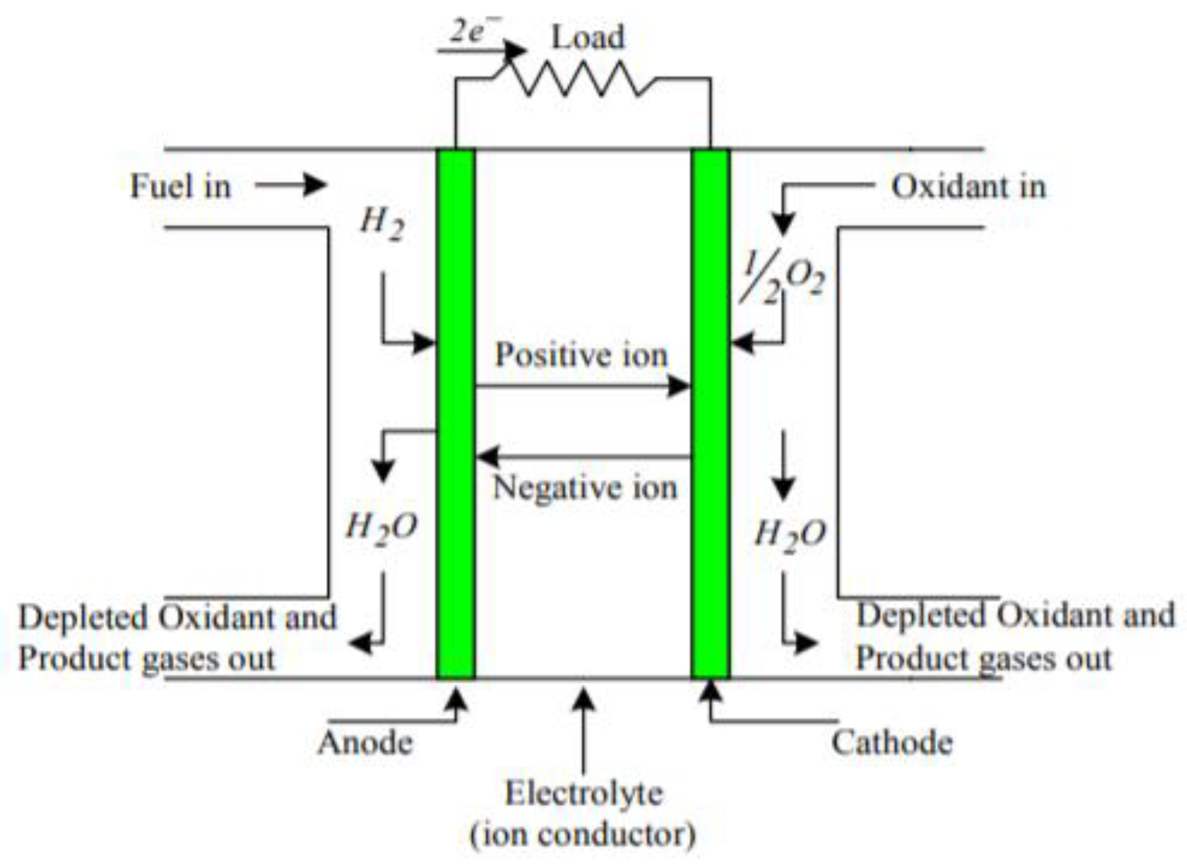
4. Principles of Fuel Cell
4.1. Types of Fuel Cell
4.1.1. Solid Oxide Fuel Cell (SOFC)
4.1.2. Direct Methanol Fuel Cell (DMFC)
4.1.3. Phosphoric Acid Fuel Cell (PAFC)
4.1.4. Polymer Electrolyte Membrane Fuel Cell (PEMFC)
4.1.5. Alkaline Fuel Cells (AFC)
4.1.6. Unitized Reversible Fuel Cell
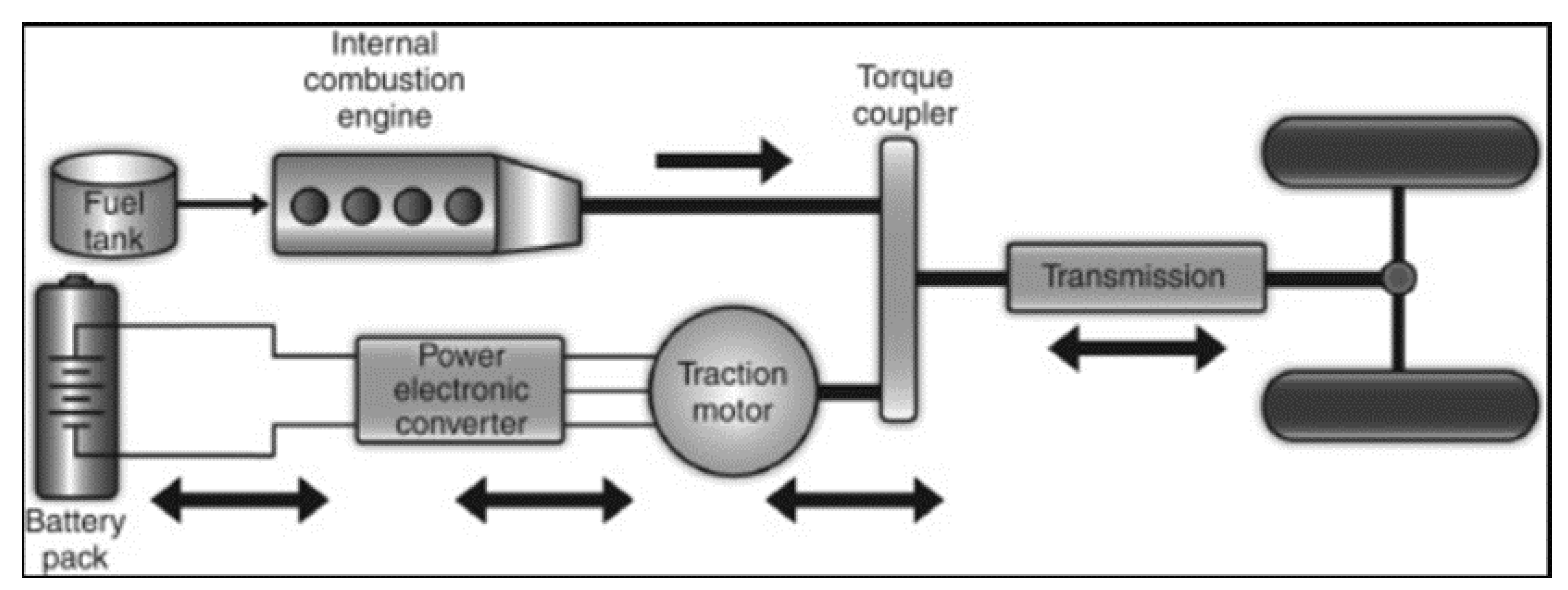
5. Fuel Cell Hybrid Vehicles
5.1. Parallel Hybrid
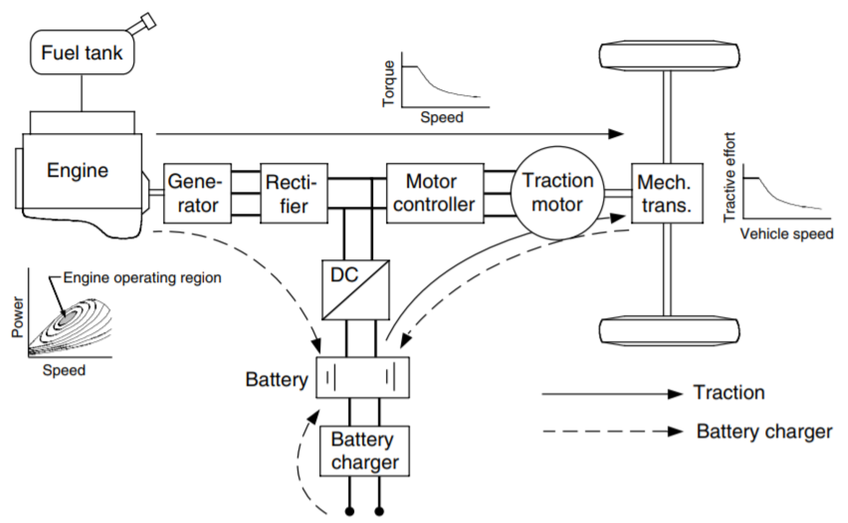
5.2. Series Hybrid
5.3. Series-Parallel Hybrid
6. Control Strategies to Make FCV More Efficient
- Peaking Power Source Strategy (PPSS)
- Operating Mode Control Strategy (OMCS)
- Fuzzy Logic Control Strategy (FLCS)
- Equivalent Consumption Minimization Strategy (ECMS)
6.1. Peaking Power Source Strategy (PPSS)
6.2. Operating Mode Control Strategy (OMCS)
6.3. Fuzzy Logic Control Strategy (FLCS)
6.4. Equivalent Consumption Minimization Strategy (ECMS)
7. Conclusions
Author Contributions
Funding
Conflicts of Interest
Abbreviation
| AFC | Alkaline Fuel Cell |
| BAT | Battery |
| BEV | Battery electric vehicle |
| CH2 | Compressed Hydrogen |
| CV | Conventional vehicle |
| DMFC | Direct methanol fuel cell |
| ECMS | Equivalent Consumption Minimization Strategy |
| FC | Fuel cell |
| FCEV | Fuel cell electric vehicle |
| FCV | Fuel cell vehicle |
| FLCS | Fuzzy Logic Control Strategy |
| HRS | Hydrogen refueling stations |
| ICE | Internal combustion engine |
| LH2 | Liquid Hydrogen |
| OMCS | Operating Mode Control Strategy |
| PAFC | Phosphoric acid fuel cell |
| PEMFC | Polymer electrolyte membrane fuel cell |
| PPSS | Peaking Power Source Strategy |
| SCAP | Super Capacitor |
| SOC | State of Charge |
| SOFC | Solid oxide fuel cells |
| URFC | Unitized regenerative fuel cell |
| YSZ | Yttrium stabilized zirconia |
References
- Hosseini, S.E.; Andwari, A.M.; Wahid, M.A.; Bagheri, G. A review on green energy potentials in Iran. Renew. Sustain. Energy Rev. 2013, 27, 533–545. [Google Scholar] [CrossRef]
- Granovskii, M.; Dincer, I.; Rosen, M.A. Greenhouse gas emissions reduction by use of wind and solar energies for hydrogen and electricity production: Economic factors. Int. J. Hydrogen Energy 2007, 32, 927–931. [Google Scholar] [CrossRef]
- Derbeli, M.; Barambones, O.; Sbita, L.; Derbeli, M.; Barambones, O.; Sbita, L. A Robust Maximum Power Point Tracking Control Method for a PEM Fuel Cell Power System. Appl. Sci. 2018, 8, 2449. [Google Scholar] [CrossRef]
- Hosseini, S.E.; Wahid, M.A.; Aghili, N. The scenario of greenhouse gases reduction in Malaysia. Renew. Sustain. Energy Rev. 2013, 28, 400–409. [Google Scholar] [CrossRef]
- Eriksson, E.L.V.; Gray, E.M.A. Optimization and integration of hybrid renewable energy hydrogen fuel cell energy systems—A critical review. Appl. Energy 2017, 202, 348–364. [Google Scholar] [CrossRef]
- Heywood, J.B. Internal Combustion Engine Fundamentals; McGraw-Hill Education: New York, NY, USA, 1988. [Google Scholar]
- Costilla-Reyes, A.; Erbay, C.; Carreon-Bautista, S.; Han, A.; Sánchez-Sinencio, E. A Time-Interleave-Based Power Management System with Maximum Power Extraction and Health Protection Algorithm for Multiple Microbial Fuel Cells for Internet of Things Smart Nodes. Appl. Sci. 2018, 8, 2404. [Google Scholar] [CrossRef]
- Kerviel, A.; Pesyridis, A.; Mohammed, A.; Chalet, D.; Kerviel, A.; Pesyridis, A.; Mohammed, A.; Chalet, D. An Evaluation of Turbocharging and Supercharging Options for High-Efficiency Fuel Cell Electric Vehicles. Appl. Sci. 2018, 8, 2474. [Google Scholar] [CrossRef]
- Wang, C.; Nehrir, M.H.; Gao, H. Control of PEM Fuel Cell Distributed Generation Systems. IEEE Trans. Energy Convers. 2006, 21, 586–595. [Google Scholar] [CrossRef]
- Somekawa, T.; Nakamura, K.; Kushi, T.; Kume, T.; Fujita, K.; Yakabe, H. Examination of a high-efficiency solid oxide fuel cell system that reuses exhaust gas. Appl. Therm. Eng. 2017, 114, 1387–1392. [Google Scholar] [CrossRef]
- Ayad, M.Y.; Becherif, M.; Henni, A. Vehicle hybridization with fuel cell, supercapacitors and batteries by sliding mode control. Renew. Energy 2011, 36, 2627–2634. [Google Scholar] [CrossRef]
- Chakraborty, U.K. A New Model for Constant Fuel Utilization and Constant Fuel Flow in Fuel Cells. Appl. Sci. 2019, 9, 1066. [Google Scholar] [CrossRef]
- Giorgi, L.; Leccese, F. Fuel Cells: Technologies and Applications. Open Fuel Cells J. 2013, 6, 1–20. [Google Scholar] [CrossRef]
- Offer, G.J.; Howey, D.; Contestabile, M.; Clague, R.; Brandon, N.P. Comparative analysis of battery electric, hydrogen fuel cell and hybrid vehicles in a future sustainable road transport system. Energy Policy 2010, 38, 24–29. [Google Scholar] [CrossRef]
- Choi, H.; Shin, J.; Woo, J. Effect of electricity generation mix on battery electric vehicle adoption and its environmental impact. Energy Policy 2018, 121, 13–24. [Google Scholar] [CrossRef]
- Aceves, S.M.; Berry, G.D.; Weisberg, A.H.; Espinosa-Loza, F.; Perfect, S.A. Advanced concepts for vehicular containment of compressed and cryogenic hydrogen. In Proceedings of the 16th World Hydrogen Energy Conference 2006 (WHEC 2006), Lyon, France, 13–16 June 2006. [Google Scholar]
- Michel, F.; Fieseler, H.; Allidiers, L. Liquid Hydrogen Technologies for Mobile Use. In Proceedings of the 16th World Hydrogen Energy Conference 2006 (WHEC 2006), Lyon, France, 13–16 June 2006. [Google Scholar]
- Paggiaro, R.; Michl, F.; Bénard, P.; Polifke, W. Cryo-adsorptive hydrogen storage on activated carbon. II: Investigation of the thermal effects during filling at cryogenic temperatures. Int. J. Hydrogen Energy 2010, 35, 648–659. [Google Scholar] [CrossRef]
- Hosseini, S.E.; Wahid, M.A. Hydrogen production from renewable and sustainable energy resources: Promising green energy carrier for clean development. Renew. Sustain. Energy Rev. 2016, 57. [Google Scholar] [CrossRef]
- Boretti, A. Novel dual fuel diesel-ammonia combustion system in advanced TDI engines. Int. J. Hydrogen Energy 2017, 42, 7071–7076. [Google Scholar] [CrossRef]
- Veziroglu, A.; MacArio, R. Fuel cell vehicles: State of the art with economic and environmental concerns. Int. J. Hydrogen Energy 2011, 36, 25–43. [Google Scholar] [CrossRef]
- Hosseini, S.E.; Wahid, M.A.; Ganjehkaviri, A. An overview of renewable hydrogen production from thermochemical process of oil palm solid waste in Malaysia. Energy Convers. Manag. 2015, 94, 415–429. [Google Scholar] [CrossRef]
- Hosseini, S.E.; Abdul Wahid, M.; Jamil, M.; Azli, A.A.M.; Mohamad, F.M. A review on biomass-based hydrogen production for renewable energy supply. Int. J. Energy Res. 2015, 39, 1597–1615. [Google Scholar] [CrossRef]
- Hibino, T.; Kobayashi, K.; Ito, M.; Ma, Q.; Nagao, M.; Fukui, M.; Teranishi, S. Efficient Hydrogen Production by Direct Electrolysis of Waste Biomass at Intermediate Temperatures. ACS Sustain. Chem. Eng. 2018, 6, 9360–9368. [Google Scholar] [CrossRef]
- Hibino, T.; Kobayashi, K.; Lv, P.; Nagao, M.; Teranishi, S.; Mori, T. An Intermediate-Temperature Biomass Fuel Cell Using Wood Sawdust and Pulp Directly as Fuel. J. Electrochem. Soc. 2017, 164, F557–F563. [Google Scholar] [CrossRef]
- Hibino, T.; Kobayashi, K.; Ito, M.; Nagao, M.; Fukui, M. Applied Catalysis B: Environmental Direct electrolysis of waste newspaper for sustainable hydrogen production: An oxygen-functionalized porous carbon anode. Appl. Catal. B Environ. 2018, 231, 191–199. [Google Scholar] [CrossRef]
- Hibino, T.; Kobayashi, K.; Nagao, M.; Teranishi, S. Hydrogen Production by Direct Lignin Electrolysis at Intermediate Temperatures. ChemElectroChem 2017, 4, 3032–3036. [Google Scholar] [CrossRef]
- Hori, T.; Ma, Q.; Kobayashi, K.; Nagao, M. Electrolysis of humidified methane to hydrogen and carbon dioxide at low temperatures and voltages. Int. J. Hydrogen Energy 2019, 44, 2454–2460. [Google Scholar] [CrossRef]
- Alternative Fuels Data Center: How Do Fuel Cell Electric Vehicles Work Using Hydrogen? Available online: https://afdc.energy.gov/vehicles/how-do-fuel-cell-electric-cars-work (accessed on 21 May 2019).
- Devrim, Y.; Devrim, H.; Eroglu, I. Development of 500 W PEM fuel cell stack for portable power generators. Int. J. Hydrogen Energy 2015, 40, 7707–7719. [Google Scholar] [CrossRef]
- Davis, C.; Edelstein, B.; Evenson, B.; Brecher, A.; Cox, D. Hydrogen Fuel Cell Vehicle Study. Presented at the Panel on Public Affairs (POPA), American Physical Society, 12 June 2003. [Google Scholar]
- Atkinson, K.; Roth, S.; Hirscher, M.; Grünwald, W. Carbon nanostructures: An efficient hydrogen storage medium for fuel cells. Fuel Cells Bull. 2001, 4, 9–12. [Google Scholar] [CrossRef]
- Das, L.M. Hydrogen-fueled internal combustion engines. Compend. Hydrog. Energy 2016, 177–217. [Google Scholar] [CrossRef]
- Chen, P.; Xiong, Z.; Luo, J.; Lin, J.; Tan, K.L. Interaction of hydrogen with metal nitrides and imides. Nature 2002, 420, 302–304. [Google Scholar] [CrossRef]
- Ehsani, M.; Gao, Y.; Longo, S.; Ebrahimi, K. Modern Electric, Hybrid Electric, and Fuel Cell Vehicles, Third Edition; CRC Press: Boca Raton, FL, USA, 2018; ISBN 9780429504884. [Google Scholar]
- Jorgensen, S.W. Hydrogen storage tanks for vehicles: Recent progress and current status. Curr. Opin. Solid State Mater. Sci. 2011, 15, 39–43. [Google Scholar] [CrossRef]
- Greene, D.L.; Leiby, P.N.; James, B.D.; Perez, J.; Melandez, M.; Milbrandt, A.; Unnasch, S.; Rutherford, D. Analysis of the Transition to Hydrogen Fuel Cell Vehicles and the Potential Hydrogen Energy Infrastructure Requirements; Oak Ridge National Lab. (ORNL): Oak Ridge, TN, USA, 2008. [Google Scholar]
- Kirubakaran, A.; Jain, S.; and Nema, R.K. The PEM Fuel Cell System with DC / DC Boost Converter: Design, Modeling and Simulation. Int. J. Recent Trends Eng. 2009, 1, 157. [Google Scholar]
- O’Hayre, R.P.; Cha, S.-W.; Colella, W.G.; Prinz, F.B. Fuel Cell Fundamentals; John Wiley & Sons: Hoboken, NJ, USA, 2016; ISBN 9781119113805. [Google Scholar]
- Reschiotto, D. Effects of Anode Fuel Recirculation on SOFCs Fuelled with Biogas. Master’s Thesis, Politecnico di Torino, Torino, Italy, 2018. [Google Scholar]
- Yang, G.; Jung, W.; Ahn, S.-J.; Lee, D.; Yang, G.; Jung, W.; Ahn, S.-J.; Lee, D. Controlling the Oxygen Electrocatalysis on Perovskite and Layered Oxide Thin Films for Solid Oxide Fuel Cell Cathodes. Appl. Sci. 2019, 9, 1030. [Google Scholar] [CrossRef]
- NFCRC Tutorial: Solid Oxide Fuel Cell (SOFC). Available online: http://www.nfcrc.uci.edu/3/TUTORIALS/EnergyTutorial/sofc.html (accessed on 16 October 2018).
- Barbir, F. PEM Fuel Cells: Theory and Practice, 2nd ed.; Academic Press: Cambridge, MA, USA, 2013; ISBN 9780123877109. [Google Scholar]
- Yamarone, R. The Trader’s Guide to Key Economic Indicators; Bloomberg Press: Hoboken, NJ, USA, 2004; ISBN 1576601390. [Google Scholar]
- Srinivasan, S. Fuel cells: From fundamentals to applications. In Fuel Cells; Springer Science & Business Media: Boston, MA, USA, 2006; pp. 3–25. [Google Scholar]
- Wilberforce, T.; El-Hassan, Z.; Khatib, F.N.; Al Makky, A.; Baroutaji, A.; Carton, J.G.; Olabi, A.G. Developments of electric cars and fuel cell hydrogen electric cars. Int. J. Hydrogen Energy 2017, 42, 25695–25734. [Google Scholar] [CrossRef]
- Briguglio, N.; Andaloro, L.; Ferraro, M.; Antonucci, V. Fuel Cell Hybrid Electric Vehicles. In Electric Vehicles, The Benefits and Barriers; InTech: London, UK, 2011. [Google Scholar]
- Garche, J.; Jörissen, L. Applications of Fuel Cell Technology: Status and Perspectives. Electrochem. Soc. Interface 2015, 24, 39–43. [Google Scholar] [CrossRef]
- Bhosale, A.C.; Mane, S.R.; Singdeo, D.; Ghosh, P.C. Modeling and experimental validation of a unitized regenerative fuel cell in electrolysis mode of operation. Energy 2017, 121, 256–263. [Google Scholar] [CrossRef]
- Zhang, Y.; Zhang, H.; Ma, Y.; Cheng, J.; Zhong, H.; Song, S.; Ma, H. A novel bifunctional electrocatalyst for unitized regenerative fuel cell. J. Power Sources 2010, 195, 142–145. [Google Scholar] [CrossRef]
- Ito, H.; Miyazaki, N.; Ishida, M.; Nakano, A. ScienceDirect Efficiency of unitized reversible fuel cell systems. Int. J. Hydrogen Energy 2016, 41, 5803–5815. [Google Scholar] [CrossRef]
- Shukla, A.K.; Jackson, C.L.; Scott, K. The Promise of Fuel Cell-Based Automobiles. Bull. Mater. Sci. 2003, 26, 207–214. [Google Scholar] [CrossRef]
- Stefan, J.; Minott, S.J.; Norman, R.; Scott, N.R. Feasibility of Fuel Cells for Energy Conversion on Dairy Farms. In Proceedings of the ASABE Annual Meeting, Sacramento, CA, USA, July 29–August 1 2001. [Google Scholar]
- Chu, S.; Majumdar, A. Opportunities and challenges for a sustainable energy future. Nature 2012, 488, 294–303. [Google Scholar] [CrossRef]
- Mahmoud, M.; Garnett, R.; Ferguson, M.; Kanaroglou, P. Electric buses: A review of alternative powertrains. Renew. Sustain. Energy Rev. 2016, 62, 673–684. [Google Scholar] [CrossRef]
- Hardman, S.; Tal, G. Who are the early adopters of fuel cell vehicles? Int. J. Hydrogen Energy 2018, 43, 17857–17866. [Google Scholar] [CrossRef]
- Schwelm, G. Hydrogenics fueling installations in Germany, France. Fuel Cells Bull. 2009, 2009, 7. [Google Scholar] [CrossRef]
- Robledo, C.B.; Oldenbroek, V.; Abbruzzese, F.; van Wijk, A.J.M. Integrating a hydrogen fuel cell electric vehicle with vehicle-to-grid technology, photovoltaic power and a residential building. Appl. Energy 2018, 215, 615–629. [Google Scholar] [CrossRef]
- International Energy Agency. Available online: http://www.iea.org/ (accessed on 20 January 2017).
- Arena, F.; Spera, D.; Laguardia, F. What’s in the Future for Fuel Cell Vehicles? Arthur D Little: Boston, MA, USA.
- Hisschemöller, M.; Bode, R.; van de Kerkhof, M. What governs the transition to a sustainable hydrogen economy? Articulating the relationship between technologies and political institutions. Energy Policy 2006, 34, 1227–1235. [Google Scholar] [CrossRef]
- Brey, J.J.; Carazo, A.F.; Brey, R. Exploring the marketability of fuel cell electric vehicles in terms of infrastructure and hydrogen costs in Spain. Renew. Sustain. Energy Rev. 2018, 82, 2893–2899. [Google Scholar] [CrossRef]
- Thomas, C.E. Fuel cell and battery electric vehicles compared. Int. J. Hydrogen Energy 2009, 34, 6005–6020. [Google Scholar] [CrossRef]
- Barbosa, M.J.; Rocha, J.M.; Tramper, J.; Wijffels, R.H. Acetate as a carbon source for hydrogen production by photosynthetic bacteria. J. Biotechnol. 2001, 85, 25–33. [Google Scholar] [CrossRef]
- Emadi, A.; Rajashekara, K.; Williamson, S.S.; Lukic, S.M. Topological Overview of Hybrid Electric and Fuel Cell Vehicular Power System Architectures and Configurations. IEEE Trans. Veh. Technol. 2005, 54, 763–770. [Google Scholar] [CrossRef]
- Liu, Y.-L.; Tong, C.-C.; Jwo, W.-S.; Lin, S.-J. Design an Intelligent Neural-Fuzzy Controller for Hybrid Motorcycle. In NAFIPS 2007. 2007 Annual Meeting of the North American Fuzzy Information Processing Society; IEEE: San Diego, CA, USA, 24–27 June 2007; pp. 283–288. [Google Scholar]
- Ahn, J.K.; Jung, K.H.; Kim, D.H.; Jin, H.B.; Kim, H.S.; Hwang, S.H. Analysis of a regenerative braking system for Hybrid Electric Vehicles using an Electro-Mechanical Brake. Int. J. Automot. Technol. 2009, 10, 229–234. [Google Scholar] [CrossRef]
- Gao, Y.; Chen, L.; Ehsani, M. Investigation of the Effectiveness of Regenerative Braking for EV and HEV. In SAE Techical Paper; SAE International: Warrendale, PA, USA, 1999. [Google Scholar]
- Arora, A.; Medora, N.K.; Livernois, T.; Swart, J. Safety of Lithium-Ion Batteries for Hybrid Electric Vehicles. Electr. Hybrid Veh. 2010, 463–491. [Google Scholar] [CrossRef]
- Walters, J.; Husted, H.; Rajashekara, K. Comparative Study of Hybrid Powertrain Strategies. SAE Trans. 2001, 110, 1944–1953. [Google Scholar]
- Hogarth, W.H.J.; Benziger, J.B. Dynamics of Autohumidifed PEM Fuel Cell Operation. J. Electrochem. Soc. 2006, 153, A2139. [Google Scholar] [CrossRef][Green Version]
- Hasan, A.; Guo, S.; Wahab, M. Simulation of a proton exchange membrane fuel cell. World J. Eng. 2011, 8, 109–115. [Google Scholar] [CrossRef]
- Guarnieri, M.; Moro, F. A novel circuit model of a proton exchange membrane fuel cell. COMPEL Int. J. Comput. Math. Electr. Electron. Eng. 2010, 29, 1562–1572. [Google Scholar] [CrossRef]
- Kato, M.; Henry, A.; Graham, S.; Doan, D.H.; Fushinobu, K. Molecular dynamics simulation of oxygen transport characteristics in the electrolyte membrane of PEMFC. Int. J. Numer. Methods Heat Fluid Flow 2018, 28, 289–296. [Google Scholar] [CrossRef]
- Electrochemical Society. Journal of the Electrochemical Society; Electrochemical Society: Pennington, NJ, USA, 1948. [Google Scholar]
- Grammatico, S.; Balluchi, A.; Italia, D. A series-parallel hybrid electric powertrain for industrial vehicles. In Proceedings of the Automotive Control View Project; IEEE: Piscataway, NJ, USA, 2010. [Google Scholar]
- Amodeo, S.J.; Chiacchiarini, H.G.; Solsona, J.A.; Busada, C.A. High-performance sensorless nonlinear power control of a flywheel energy storage system. Energy Convers. Manag. 2009, 50, 1722–1729. [Google Scholar] [CrossRef]
- Xiong, W.; Zhang, Y.; Yin, C. Optimal energy management for a series–parallel hybrid electric bus. Energy Convers. Manag. 2009, 50, 1730–1738. [Google Scholar] [CrossRef]
- Hu, X.; Murgovski, N.; Johannesson, L.; Egardt, B. Energy efficiency analysis of a series plug-in hybrid electric bus with different energy management strategies and battery sizes. Appl. Energy 2013, 111, 1001–1009. [Google Scholar] [CrossRef]
- He, X.; Jiang, Y. Review of hybrid electric systems for construction machinery. Autom. Constr. 2018, 92, 286–296. [Google Scholar] [CrossRef]
- Dreier, D.; Silveira, S.; Khatiwada, D.; Fonseca, K.V.O.; Nieweglowski, R.; Schepanski, R. Well-to-Wheel analysis of fossil energy use and greenhouse gas emissions for conventional, hybrid-electric and plug-in hybrid-electric city buses in the BRT system in Curitiba, Brazil. Transp. Res. Part D Transp. Environ. 2018, 58, 122–138. [Google Scholar] [CrossRef]
- Camara, M.B.; Gualous, H.; Gustin, F.; Berthon, A. Design and New Control of DC/DC Converters to Share Energy Between Supercapacitors and Batteries in Hybrid Vehicles. IEEE Trans. Veh. Technol. 2008, 57, 2721–2735. [Google Scholar] [CrossRef]
- Bauman, J.; Kazerani, M. An Analytical Optimization Method for Improved Fuel Cell–Battery–Ultracapacitor Powertrain. IEEE Trans. Veh. Technol. 2009, 58, 3186–3197. [Google Scholar] [CrossRef]
- Bauman, J.; Kazerani, M. A Comparative Study of Fuel-Cell–Battery, Fuel-Cell–Ultracapacitor, and Fuel-Cell–Battery–Ultracapacitor Vehicles. IEEE Trans. Veh. Technol. 2008, 57, 760–769. [Google Scholar] [CrossRef]
- Thounthong, P.; Raël, S.; Davat, B. Energy management of fuel cell/battery/supercapacitor hybrid power source for vehicle applications. J. Power Sources 2009, 193, 376–385. [Google Scholar] [CrossRef]
- Cipollone, R.; Di Battista, D.; Marchionni, M.; Villante, C. Model based Design and Optimization of a Fuel Cell Electric Vehicle. Energy Procedia 2014, 45, 71–80. [Google Scholar] [CrossRef][Green Version]
- Ning, Q.; Xuan, D.; Kim, Y. Modeling and control strategy development for fuel cell hybrid vehicles. Int. J. Automot. Technol. 2010, 11, 229–238. [Google Scholar] [CrossRef]
- Bizon, N.; Thounthong, P. Fuel economy using the global optimization of the Fuel Cell Hybrid Power Systems. Energy Convers. Manag. 2018, 173, 665–678. [Google Scholar] [CrossRef]
- Gao, L.; Dougal, R.A.; Liu, S. Power Enhancement of an Actively Controlled Battery/Ultracapacitor Hybrid. IEEE Trans. Power Electron. 2005, 20, 236–243. [Google Scholar] [CrossRef]


| Fuel Cell | Abbreviation | Membrane |
|---|---|---|
| Solid Oxide Fuel cells | SOFC | Yttria-stabilized zirconia |
| Direct methanol fuel cell | DMFC | Solid polymer electrolyte (Nafion) |
| Phosphoric Acid fuel cell | PAFC | Phosphoric Acid (H3PO4) |
| Polymer electrolyte fuel cell Or Proton exchange membrane | PEMFC | Solid polymer electrolyte (Nafion) |
| Alkaline fuel cell | AFC | Aqueous solution Potassium Hydroxide (KOH) |
© 2019 by the authors. Licensee MDPI, Basel, Switzerland. This article is an open access article distributed under the terms and conditions of the Creative Commons Attribution (CC BY) license (http://creativecommons.org/licenses/by/4.0/).
Share and Cite
Manoharan, Y.; Hosseini, S.E.; Butler, B.; Alzhahrani, H.; Senior, B.T.F.; Ashuri, T.; Krohn, J. Hydrogen Fuel Cell Vehicles; Current Status and Future Prospect. Appl. Sci. 2019, 9, 2296. https://doi.org/10.3390/app9112296
Manoharan Y, Hosseini SE, Butler B, Alzhahrani H, Senior BTF, Ashuri T, Krohn J. Hydrogen Fuel Cell Vehicles; Current Status and Future Prospect. Applied Sciences. 2019; 9(11):2296. https://doi.org/10.3390/app9112296
Chicago/Turabian StyleManoharan, Yogesh, Seyed Ehsan Hosseini, Brayden Butler, Hisham Alzhahrani, Bhi Thi Fou Senior, Turaj Ashuri, and John Krohn. 2019. "Hydrogen Fuel Cell Vehicles; Current Status and Future Prospect" Applied Sciences 9, no. 11: 2296. https://doi.org/10.3390/app9112296
APA StyleManoharan, Y., Hosseini, S. E., Butler, B., Alzhahrani, H., Senior, B. T. F., Ashuri, T., & Krohn, J. (2019). Hydrogen Fuel Cell Vehicles; Current Status and Future Prospect. Applied Sciences, 9(11), 2296. https://doi.org/10.3390/app9112296