Article

A Precise Prediction of Tunnel Deformation Caused by Circular Foundation Pit Excavation

1
Department of Civil Engineering, Huaiyin Institute of Technology, Huai’an 223001, China
2
Department of Civil Engineering, Nanjing Tech University, Nanjing 211816, China
*
Author to whom correspondence should be addressed.
Appl. Sci. 2019, 9(11), 2275; https://doi.org/10.3390/app9112275
Submission received: 29 April 2019 / Revised: 29 May 2019 / Accepted: 30 May 2019 / Published: 2 June 2019

Abstract

:
In comparison with tetragonal retaining structures, circular retaining structures have an advantage in terms of controlling the deformation caused by foundation excavation, and are a reasonable choice in engineering practice. Many results have been obtained regarding the effect of tetragonal excavation on the deformation of an adjacent tunnel. Nevertheless, a sufficient understanding of the circular excavation’s effect on the deformation of an adjacent tunnel is currently lacking. Therefore, this study focused on the problem of precise predicting tunnel deformation below a circular excavation. A numerical model was established to calculate the tunnel deformation caused by the circular excavation. An advanced nonlinear constitutive model, known as a hypoplasticity model, which can capture path-dependent and strain-dependent soil stiffness even at small strains, was adopted. The models and their associated parameters were calibrated by centrifuge test results reported in the literature. The deformation mechanism was revealed, and the calculated results were compared with those obtained with a square excavation and the same excavation amount. The differences between the deformations caused by these two types of excavation shapes were analyzed. It was found that under equal excavation area conditions, the excavation-induced deformations of the metro tunnel below a circular excavation were approximately 1.18–1.22 times greater than those below a square excavation. The maximum tunnel tensile bending strain caused by the circular excavation was 32% smaller than that caused by the square excavation. By comparing with the measured results, it is proved that the proposed numerical method can provide effective reference for engineers to analyze soil-structure problems.

1. Introduction

With urban development, a large number of excavation works have been conducted. Stress relief caused by basement excavation will inevitably affect surrounding subway tunnels. Many research results have been obtained with regard to the effect of tetragonal excavation on the deformation of an adjacent metro tunnel. The main contents of this study are as follows: geometry of the excavation [1,2]; relative position of tunnel and excavation [3,4,5,6,7]; excavation conditions and reinforcement method [8,9,10,11]; tunnel lining stiffness [4] and diameter of tunnel lining [1]; different soil constitutive models [12]; soil relative density and retaining wall stiffness [13]; influence zone [14] and calculation methods [15,16,17].
However, existing studies have mainly focused on analyzing the tunnel response caused by the unloading of the tetragonal basement excavation. With the rapid development of urban construction, the development and utilization of underground space is rapidly increasing and more and more foundation basements are constructed as circular foundation basements [18,19,20,21]. Unlike the traditional tetragonal rectangular basement, a circular basement can make full use of the circular arch effect, such that the force of the structure becomes more reasonable.
Existing circular basement studies have mainly focused on the soil pressure around the basement and the retaining structure’s deformation caused by the excavation [22,23,24,25,26,27,28,29,30]. However, few studies have focused on the deformation of surrounding foundations and buildings, which is caused by the unloading of the circular excavation. Considering the many differences between circular and tetragonal basements, it is theoretically and practically significant to evaluate the effect of circular basement excavation on the deformation of the surrounding structure to reduce damages.
The objective of this study was to investigate the contribution of circular basement construction to the deformation of a nearby existing tunnel, and to reveal the tunnel deformation mechanism. Three-dimensional numerical analyses using advanced constitute model combined with accurate numerical simulation techniques were conducted based on the reported centrifuge model test. The effect of the excavation shape and the tunnel and soil responses were analyzed with the expectation that the results may provide a useful reference for engineering practice.

2. Introduction of a Centrifuge Model Test

A centrifuge model test, which models the interaction between a new basement excavation and an existing tunnel was carried, out as shown in Figure 1 [7]. The centrifuge acceleration of the test was 60 g. The length, width, and depth of the excavation was 300 × 300 × 150 mm, which is equal to 18 × 18 × 9 m in the prototype, respectively. The Young’s modulus of the model diaphragm wall was 70 GPa, and was equal to that of the model tunnel. The model tunnel had a diameter of 100 mm, length of 1,200 mm, and thickness of 3 mm, which is equal to 6 m, 72 m, and 0.18 m in the prototype, respectively. The details of the proposed centrifuge test have been reported by Ng et al. (2013) [7]. It is also noted that the following measured results in this paper are all reported by Ng et al. (2013) [7].

3. Finite Element Model

3.1. Finite Element Mesh and Boundary Condition

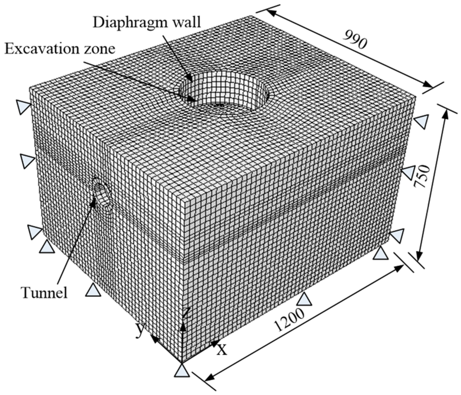
In this study, the finite element software ABAQUS [31] was used. A three-dimensional finite element mesh was built as shown in Figure 2. The finite element mesh in this model had a length of 1200 mm, width of 990 mm, and depth of 750 mm. The square basement excavation (on plan) was the same as that in the centrifuge model test, with a length and width of 300 × 300 mm (equal to 18 × 18 m in the prototype). Preliminary calculations checked the influence of the mesh density (13,540–86,590 elements in a structured or unstructured mesh, respectively) and of the element type (triangle or quadrilateral elements with linear interpolation). The influence of these factors on the results has been shown to be small. However, for precise and quick convergence, 86,950 elements in a structured mesh with quadrilateral element type was adopted. Based on the principle of the excavation amount being equal to the square excavation amount recorded in the test, a circular excavation was conducted with a diameter of 339 mm (equal to 20.3 m in the prototype). The basement excavation depth was 150 mm, which is equal to 9 m in the prototype. The embedment depth of the diaphragm wall was 225 mm, which is equal to 13.5 m in the prototype. The sand and the diaphragm wall were simulated by an eight-node brick element, and the tunnel was simulated by a four-node shell element. To consider the friction boundary condition, pin supports were adopted both at the vertical sides and at the base of the model. Interface elements were adopted at the soil-diaphragm wall and at the soil-tunnel interfaces. Each interface element used is described by zero-thickness slip element, assigned with the Coulomb friction law. The friction coefficient (µ) and limiting relative displacement (γlim) at which slippage occurs are controlled by two input parameters for each slip element. The interface friction coefficient, µ, is derived from µ = tanδ, where δ is the interface friction angle, which is taken as 20° (i.e., 2/3 of the critical friction angle of soil). The limiting displacement of 5 mm is assumed to achieve full mobilization of the interface friction. It is noted that the initial compaction due to air pressure was not taken into account.

3.2. Constitutive Model and Model Parameters

In the references paper [12], the ability of three different soil constitutive models to predict a tunnel’s response to basement excavation has been evaluated. It is found that the hypoplastic model yielded the best predictions of tunnel heave among the adopted models. The nonlinearity of soil can be captured by a hypoplastic (HP) constitutive model. Various HP models have been developed in the 1990s (Kolymbas 1991; Gudehus 1996; Von Wolffersdorff 1996; Wu et al. 1996) [32,33,34,35] as well as recently (Mašín 2012 2014, 2013) [36,37,38]. The model proposed by Von Wolffersdorff (1996) [34] was adopted to describe the behavior of Toyoura sand. This model was incorporated into the software package ABAQUS using open-source implementation which can be freely downloaded from the web (Gudehus et al. 2008) [39]. The model specifies eight material parameters (φc, hs, n, ed0, ec0, ei0, α and β). Niemunis and Herle (1997) [40] improved the model for predictions of small-strain stiffness and the recent stress history, leading to five additional parameters (mT, mR, R, βr and χ). See Table 1 and the literature mentioned above for their physical meaning.
Six parameters of Toyoura sand (φc, hs, n, ed0, ec0 and ei0) were obtained from Herle and Gudehus (1999) [41], while the triaxial test results reported by Maeda and Miura (1999) [42] were used to calibrate the parameters of α and β. Five parameters (mT, mR, R, βr and χ) of the intergranular strain can be calibrated from the stiffness degradation curve of Toyoura sand (Iwasaki et al. 1978) [43], as shown in Figure 3. The void ratio of soil was considered as a state variable in the HP model. The parameter selection list is presented in Table 1. The parameter selection procedure and values have been reported by Ng et al. (2015) [12]. The tunnel and diaphragm wall can be considered as an elastic material. Their elastic modulus and Poisson’s ratio were 70 GPa and 0.2, respectively.

3.3. Numerical Modelling Procedures

The gradual unloading method was adopted to simulate the excavation. Figure 3 shows the flow chart of specific simulation process and as follows.
  • Establish the initial stress conditions using K0 = 0.5. Apply the same amounts of vertical and horizontal pressure as that in the centrifuge test to the formation level and diaphragm wall, respectively.
  • Incrementally increase the gravitational acceleration of the whole model from 1 g to 60 g in four steps, i.e., from 1 g, to 15 g, to 30 g, to 45 g, and finally to 60 g. Simultaneously, apply pressure to the formation level and the wall.
  • Decrease the amounts of vertical and horizontal pressure gradually in each excavation stage to simulate excavation until a depth of 9 m is reached.

4. Result Interpretation

4.1. Tunnel Heave in Longitudinal Direction

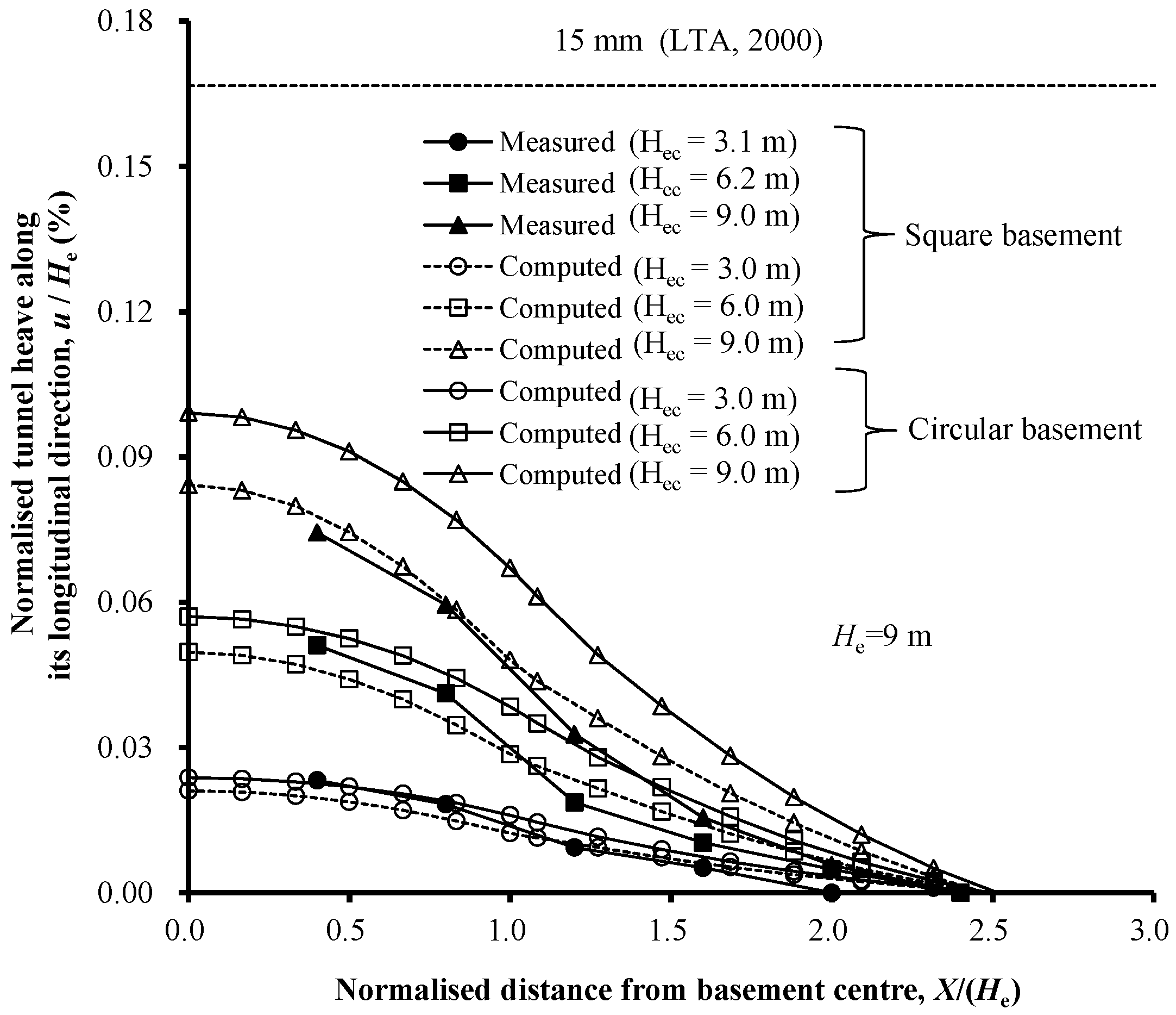
Figure 4 shows the measured tunnel heave computed by numerical analyses for both the square and the circular basement excavations. It can be seen that the computed tunnel heave was generally in agreement with the measured magnitude and distribution values. The tunnel heave in the existing tunnel was caused by stress relief, as shown in Figure 5. With the increase of the basement excavation depth, the tunnel heave increased. After the basement excavation, the measured tunnel heave reached 0.07% He (He is the basement depth) at a distance of 0.4 He from the basement center, and reduced to zero at a distance of 2.4 He from the basement center. The computed maximum value of the tunnel heave was 0.084% He and 0.099% He for the square and circular basement excavations, respectively, with a similar trend distribution. By comparing the computed tunnel heave caused by a different basement shape, it was found that the maximum tunnel heave caused by the unloading of the circular excavation was 1.18 times greater than that of the square excavation with the same excavation amount. According to the provisions of the Land Transport Authority [44], the allowable maximum tunnel heave value is 15 mm (i.e., 0.170% He, as shown in Figure 4). The computed tunnel heave ranged in the standard allowable value and also in the measured value. From the above analysis, it was determined that the tunnel heave caused by the circular basement excavation was 18% larger than that caused by the square basement excavation. Additionally, if a circular basement is adopted, and assuming that the tunnel heave caused by the square basement is in a critical state, it is essential to take corresponding reinforcement measures.

4.2. Stress Distribution around the Tunnel Lining

To explain the reason for the occurrence of tunnel heave, Figure 5 shows the stress distribution in the soil element around the tunnel crown. The stress increases are shown as positive values, while the stress decreases are shown as negative values. The basement excavation with two different shapes predicted almost similar vertical stress patterns for the soil elements around the tunnel crown. A great decrease in the vertical stress beneath the basement was observed after the excavation. Additionally, it was observed that the vertical soil stress was uniform beneath the basement, and increased greatly just beneath the diaphragm wall. The vertical stress increased by 64 kPa and 75 kPa for the square and circular basement, respectively. The largest stress change for the soil element was caused by the circular basement around the tunnel crown and was 17% larger than that of the square basement. Thus, the tunnel heave caused by the circular basement excavation was larger than that caused by the square basement excavation, as shown in Figure 4. At a distance 0.6 He from the diaphragm wall location, the stress change in the soil element was less than 20 kPa. Based on the Building department of the government of Hong Kong Special Administrative Region, HKSAR [45], the stress change in this case did not exceed the proposed limit value (i.e., ±20 kPa).

4.3. Tunnel Diameter Change

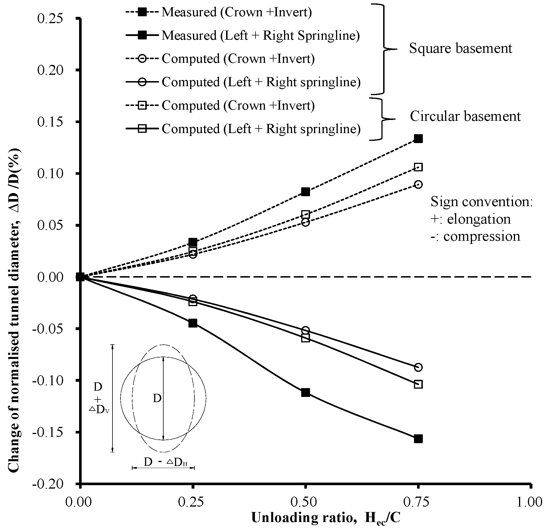
Figure 6 shows the tunnel diameter (D) change varying with Hec/C (defined as the unloading ratio), where Hec is the current excavation depth and C is the tunnel cover depth. The positive value represents the elongation, while the negative value represents compression. The tunnel lining caused by both basement excavation types was elongated vertically and compressed horizontally. It is clear that with the increase of the basement excavation depth, the elongation (ΔDV) and compression (ΔDH) of the tunnel lining increased. The square and circular basement resulted in a maximum change in the tunnel diameter by 0.09% D and 0.11% D, respectively. The maximum tunnel diameter change caused by the circular basement excavation was 22% larger than that caused by the square basement.
To better understand the tunnel diameter change for the two different types of basement excavation, the earth pressure change around the tunnel is shown in Figure 7, where it can be seen that the maximum earth pressure change occurred in the soil around the tunnel crown, while a smaller change occurred at the springlines, and little change occurred at the invert. Because the earth pressure reduction was larger at the crown than at the springlines, the tunnel lining was elongated vertically and compressed horizontally as shown in Figure 6. By comparing the two types of basement excavation, the earth pressure change at the tunnel crown and invert was almost the same because of the same excavation amount assumed by the model. However, owing to the effect of arching, the earth pressure change for the other soil elements of the square basement was smaller than that in the circular basement excavation. Thus, the tunnel diameter change caused by the circular basement excavation was larger than that caused by the square basement, as shown in Figure 6. Based on the recommendations of the British Tunnelling Society [46], the maximum tunnel lining change ((ΔDV + ΔDH)/D) should not exceed 2%. Thus, it was determined that the maximum deformation of the tunnel (i.e., 0.16% D) was smaller than the proposed allowable limit.

4.4. Bending Strain at the Tunnel Lining

The bending strains computed at the tunnel lining in the transverse direction were compared with the measured values, as shown in Figure 8a. The positive value represents the tensile strain, and the negative value represents the compressive strain. In comparison with the measured results, the computed results for both basement types exhibited similar trends. Moreover, the symmetrical bending strain distribution with regard to the tunnel centerline could be determined. The compressive strain occurred at the tunnel springlines, while the tensile strain occurred at the other tunnel elements. In the transverse direction, the maximum tensile bending strain was 91 με and 108 με for the square and circular basement excavation, respectively. There was only a small change in the transverse direction for these two excavations types, not only in the magnitude, but also in the distribution. Thus it was concluded that, in the transverse direction, the basement shape had little influence on the tunnel’s bending strain. Based on the American Concrete Institute [35], the maximum tensile strain was 150 με. The computed bending strains did not exceed the given allowable limit nor the measured value, assuming that zero bending strain occurred before the basement construction.
Figure 8b shows the bending strains computed after the excavation in the longitudinal direction in comparison with the measured values. The positive sign denotes the tensile strain, while the negative sign denotes the compressive strain occurring at the tunnel lining crown. Similar trends were observed in the measured and computed results. With regard to the basement center, it was found that the distribution of the bending strain was symmetrical. For the square and circular basement, the maximum tensile strain computed by the numerical method was 86 με and 65 με, respectively. The computed maximum tunnel lining bending strain in the longitudinal direction, which was caused by the circular excavation, was 32% smaller than that caused by the square excavation. Based on ACI [47], cracks may occur in the tunnel lining assuming that the tensile strain exceeds 85 με before the circular basement excavation.

5. Conclusions

This paper studies the tunnel deformation caused by circular excavations; the problem is tackled numerically by means an advanced nonlinear hypoplasticity constitutive model, which is able to capture the path-dependent and strain-dependent soil stiffness, even at small strains. The numerical analysis is accompanied by an experimental calibration of the parameters based on centrifuge tests. The effect of the excavation shape and the tunnel and soil responses were analyzed. The precise prediction method is useful for practical applications and can represent a key reference the design of tunnel structures, accounting for the soil-structural interaction. The comparisons of the predicted results can be regarded as the verification of different design analyses, carried out by practicing engineers. Based on the comparisons between measured and computed results, the following conclusions may be drawn:
(a)
Tunnel heave occurred in the existing tunnel lining, owing to stress relief above the existing tunnel. Thus, the tunnel heave caused by the circular basement excavation was 18% larger than that caused by the square basement.
(b)
The tunnel lining caused by both basement excavation types was elongated vertically and compressed horizontally with the basement excavation depth. The maximum tunnel diameter change caused by the circular basement excavation was 22% larger than that caused by the square basement excavation.
(c)
In the transverse direction, the compressive strains were recorded at the tunnel springlines, while the tensile strains arose at the other tunnel elements. The basement shape had little influence on the tunnel bending strain. In the tunnel’s longitudinal direction, the symmetrical bending strain distribution could be determined with regard to the basement excavation centerline. The computed maximum tunnel bending strain caused by the circular excavation was 32% smaller than that caused by the square excavation.
(d)
Under identical excavation area conditions, the extent of the influence of the stress relief caused by the circular excavation was wider and deeper than that caused by the square excavation. This implies that controlling the deformation of a metro tunnel under excavation depends mainly on the length of the metro tunnel passing through the excavation area, rather than on the excavation shape.

Data Availability Statement

The computed data used to support the findings of this study are included within the article. Previously reported measured data were used to support this study and are available at [https://doi.org/10.1139/cgj-2012-0423, https://doi.org/10.1139/cgj-2014-0361]. These prior studies (and datasets) are cited at relevant places within the text as references [7,12].

Author Contributions

Conceptualization, H.S.; methodology, H.S.; software, H.S. and S.C.; validation, H.S. and L.W.; formal analysis, H.S. and L.W.; investigation, H.S. and H.D.; resources, H.S. and S.C.; data curation, H.S. and H.D.; writing—original draft preparation, H.S. and L.W.; writing—review and editing, H.S. and J.Z.; visualization, H.S.; supervision, H.S.; project administration, H.S.; funding acquisition, H.S.

Funding

This research was funded by the National Natural Science Foundation of China, grant number 51708245, the Natural Science Foundation of Jiangsu Province, grant number BK20160426, and the Natural Science Foundation for Colleges and Universities in Jiangsu Province (17KJB620002, 17KJB130003, 17KJA560001).

Acknowledgments

We thank the anonymous reviewers for their valuable comments and suggestions. We thank Liwen Bianji, Edanz Editing China (www.liwenbianji.cn/ac), for editing the English text of a draft of this manuscript.

Conflicts of Interest

The authors declare that there are no conflicts of interest regarding the publication of this paper.

References

  1. Huang, X.; Schweiger, H.F.; Huang, H.W. Influence of deep excavations on nearby existing tunnels. Int. J. Geomech. 2013, 13, 170–180. [Google Scholar] [CrossRef]
  2. Shi, J.W.; Ng, C.W.; Chen, Y.H. Three-dimensional numerical parametric study of the influence of basement excavation on existing tunnel. Comput. Geotech. 2015, 63, 146–158. [Google Scholar] [CrossRef]
  3. Doležalová, M. Tunnel complex unloaded by a deep excavation. Comput. Geotech. 2001, 28, 469–493. [Google Scholar] [CrossRef]
  4. Sharma, J.S.; Hefny, A.M.; Zhao, J.; Chan, C.W. Effect of large excavation on displacement of adjacent MRT tunnels. Tunn. Undergr. Space Technol. 2001, 16, 93–98. [Google Scholar] [CrossRef]
  5. Zheng, G.; Wei, S.W. Numerical analysis of influence of overlying pit excavation on existing tunnels. J. Cent. South Univ. Technol. 2008, 15, 69–75. [Google Scholar] [CrossRef]
  6. Huang, X.; Huang, H.W.; Zhang, D.M. Centrifuge modeling of deep excavation over existing tunnels. Geotech. Eng. 2014, 167, 3–18. [Google Scholar] [CrossRef]
  7. Ng, C.W.; Shi, J.; Hong, Y. Three-dimensional centrifuge modelling of basement excavation effects on an existing tunnel in dry sand. Can. Geotech. J. 2013, 50, 874–888. [Google Scholar] [CrossRef]
  8. Hu, Z.F.; Yue, Z.Q.; Zhou, J.; Tham, L.G. Design and construction of a deep excavation in soft soils adjacent to the Shanghai Metro tunnels. Can. Geotech. J. 2003, 40, 933–948. [Google Scholar] [CrossRef] [Green Version]
  9. Gao, G.; Gao, M.; Yang, C. Influence of deep excavation on deformation of operating metro tunnels and countermeasures. Chin. J. Geotech. Eng. 2010, 32, 453–459. [Google Scholar]
  10. Zheng, G.; Du, Y.; Diao, Y. Optimization Analysis of Efficiency of Isolation Piles Incontrolling the Deformation of Existing Tunnels Adjacent to Deep Excavation. Chin. J. Rock Mech. Eng. 2015, 34, 3499–3509. [Google Scholar]
  11. Feng, S.J.; Gao, G.Y.; AI, H.T. Deformation analysis of group excavation adjacent to subway tunnels. Chin. J. Geotech. Eng. 2008, 30, 112–117. [Google Scholar]
  12. Ng, C.W.; Sun, H.S.; Lei, G.H.; Shi, J.W.; Mašín, D. Ability of three different soil constitutive models to predict a tunnel’s response to basement excavation. Can. Geotech. J. 2015, 52, 1685–1698. [Google Scholar] [CrossRef]
  13. Ng, C.W.; Shi, J.W.; David, M.; Sun, H.S.; Lei, G.H. Influence of sand density and retaining wall stiffness on three-dimensional responses of tunnel to basement excavation. Can. Geotech. J. 2015, 52, 1811–1829. [Google Scholar] [CrossRef]
  14. Zheng, G.; Du, Y.; Diao, Y. Influenced zones for deformation of existing tunnels adjacent to excavations. Chin. J. Geotech. Eng. 2016, 38, 599–612. [Google Scholar]
  15. Zhang, Z.G.; Huang, M.S.; Wang, W.D. Evaluation of deformation response for adjacent tunnels due to soil unloading in excavation engineering. Tunn. Undergr. Space Technol. 2013, 38, 244–253. [Google Scholar] [CrossRef]
  16. Zhang, J.F.; Chen, J.J.; Wang, J.H. Prediction of tunnel displacement induced by adjacent excavation in soft soil. Tunn. Undergr. Space Technol. 2013, 36, 24–33. [Google Scholar] [CrossRef]
  17. Shi, J.; Ng, C.W.; Chen, Y. A simplified method to estimate three-dimensional tunnel responses to basement excavation. Tunn. Undergr. Space Technol. 2017, 62, 53–63. [Google Scholar] [CrossRef]
  18. Zhou, J.J.; Rao, S.L. The design and construction of large mixed foundation in west anchorage of Humen Bridge. Bridge Constr. 1995, 2, 44–47. [Google Scholar]
  19. Liu, S.X. The design of circular diaphragm wall in the four phase of the project of Qinhuangdao port coal terminal dumper. Port Eng. Technol. 1995, 4, 28–35. [Google Scholar]
  20. Zhu, F. Monitoring and Analysis of a Deep Small Diameter Circular Excavation. Master’s Thesis, Shanghai Jiao Tong University, Shanghai, China, 2007. [Google Scholar]
  21. Zhang, Z.J.; Tang, Y.; Wang, J.H. Measured deformation of a semi-circular foundation pit in Shanghai soft soils. Chin. J. Geotech. Eng. 2014, 36, 451–454. [Google Scholar]
  22. Prater, E.G. An examination of some theories of earth pressure on shaft linings. Can. Geotech. J. 1977, 14, 91–106. [Google Scholar] [CrossRef]
  23. Dong, X.P.; Guo, Q.H.; Zhou, S.H. Character and factor analysis of deformation of diaphragm wall in the cylindrical foundation pit. Chin. J. Undergr. Space Eng. 2005, 4, 196–199. [Google Scholar]
  24. Liu, F.Q.; Wang, J.H. The active earth pressure of circular pit subjected to non-uniform surcharge loading. J. Shanghai Jiaotong Univ. 2006, 40, 2134–2136. [Google Scholar]
  25. Cheng, Y.M.; Au, S.K.; Hu, Y.Y.; Wei, W.B. Active pressure for circular cut with Berezantzev’s and Prater’s theories, numerical modeling and field measurements. Soils Found. 2008, 48, 621–631. [Google Scholar] [CrossRef]
  26. Tobar, T.; Meguid, M.A. Comparative evaluation of methods to determine the earth pressure distribution on cylindrical shafts: A review. Tunn. Undergr. Space Technol. 2010, 25, 188–197. [Google Scholar] [CrossRef]
  27. Kim, K.Y.; Lee, D.S.; Cho, J. The effect of arching pressure on a vertical circular shaft. Tunn. Undergr. Space Technol. 2013, 37, 10–21. [Google Scholar] [CrossRef]
  28. Liu, F.Q. Lateral earth pressures acting on circular retaining walls. Int. J. Geomech. 2014, 14, 613–624. [Google Scholar] [CrossRef]
  29. Meguid, M.A.; Tran, V.D.H.; Chouinard, L.E. Discrete element and experimental investigations of the earth pressure distribution on cylindrical shafts. Int. J. Geomech. 2014, 14, 80–91. [Google Scholar]
  30. Zhang, J.G.; Ren, P. Numerical simulation for constructionprocess of a very deep circular pit. In Proceedings of the International Conference on Transportation Engineering, Chengdu, China, 23–25 July 2011; pp. 1786–1791. [Google Scholar]
  31. ABAQUS, Inc. ABAQUS User’s and Theory Manuals; Version 6.17; ABAQUS, Inc.: Providence Rhode Island, RI, USA, 2017. [Google Scholar]
  32. Kolymbas, D. An outline of hypoplasticity. Arch. Appl. Mech. 1991, 61, 143–151. [Google Scholar]
  33. Gudehus, G. A comprehensive constitutive equation for granular materials. Soils Found. 1996, 36, 1–12. [Google Scholar] [CrossRef]
  34. Von Wolffersdorff, P.A. A hypoplastic relationship for granular material with a predefined limit state surface. Mech. Cohesive Frict. Mater. 1996, 1, 251–271. [Google Scholar] [CrossRef]
  35. Wu, W.; Bauer, E.; Kolymbas, D. Hypoplastic constitutive model with critical state for granular materials. Mechanics of Materials 1996, 23, 45–69. [Google Scholar] [CrossRef]
  36. Mašín, D. Hypoplastic Cam-clay model. Géotechnique 2012, 62, 549–553. [Google Scholar] [CrossRef] [Green Version]
  37. Mašín, D. Clay hypoplasticity with explicitly defined asymptotic states. Acta Geotech. 2013, 8, 481–496. [Google Scholar] [CrossRef]
  38. Mašín, D. Clay hypoplasticity model including stiffness anisotropy. Géotechnique 2014, 64, 232–238. [Google Scholar] [CrossRef] [Green Version]
  39. Gudehus, G.; Amorosi, A.; Gens, A.; Herle, I.; Kolymbas, D.; Mašín, D.; Muir Wood, D.; Niemunis, A.; Nova, R.; Pastor, M.; et al. The soilmodels.info project. Int. J. Numer. Anal. Methods Geomech. 2008, 32, 1571–1572. [Google Scholar] [CrossRef]
  40. Niemunis, A.; Herle, I. Hypoplastic model for cohensionless soils with elastic strain range. Mech. Cohesive Frict. Mater. 1997, 2, 279–299. [Google Scholar] [CrossRef]
  41. Herle, I.; Gudehus, G. Determination of parameters of a hypoplastic constitutive model from properties of grain assemblies. Mech. Cohesive Frict. Mater. 1999, 4, 461–486. [Google Scholar] [CrossRef]
  42. Maeda, K.; Miura, K. Confining stress dependency of mechanical properties of sands. Soils Found. 1999, 39, 53–67. [Google Scholar] [CrossRef]
  43. Iwasaki, T.; Tatsuoka, F.; Takagi, Y. Shear moduli of sands under cyclic torsional shear loading. Soils Found. 1978, 18, 39–50. [Google Scholar] [CrossRef]
  44. LTA. Code of Practice for Railway Protection; Development & Building Control Department, Land Transport Authority (LTA): Singapore, 2000. [Google Scholar]
  45. BD. Practice Note for Authorized Persons APP-24. In Technical Notes for Guidance in Assessing the Effects of Civil Engineering Construction/Building Development on Railway Structures and Operations; Building Department of the Government of HKSAR (BD): Hong Kong, China, 2009. [Google Scholar]
  46. British Tunnelling Society (BTS). Specification for Tunnelling; Thomas Telford: London, UK, 2000. [Google Scholar]
  47. American Concrete Institute. Control of Cracking in Concrete Structures (ACI 224R-01); American Concrete Institute: Farmington Hills, MI, USA, 2001. [Google Scholar]
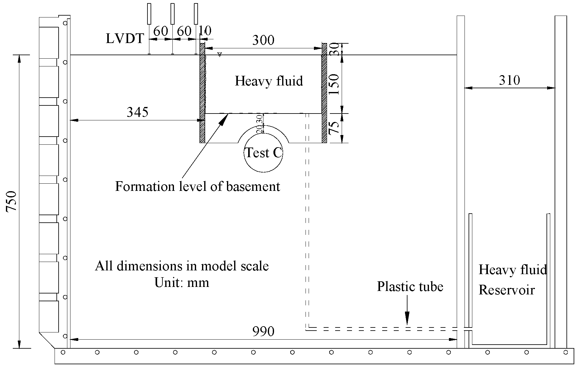
Figure 1. Layout of the proposed centrifuge model test [7].
Applsci 09 02275 g001
Figure 2. Finite element model (in model scale, unit: mm).
Applsci 09 02275 g002
Figure 3. Flow chart of the numerical modelling procedures.
Applsci 09 02275 g003
Figure 4. Measured and computed tunnel heave.
Applsci 09 02275 g004
Figure 5. Vertical stress changes in soil element around tunnel crown.
Applsci 09 02275 g005
Figure 6. Comparison of tunnel diameter change.
Applsci 09 02275 g006
Figure 7. Earth pressure change around the tunnel lining (absolute value).
Applsci 09 02275 g007
Figure 8. Additional bending strains in tunnel lining along the (a) transverse and (b) longitudinal direction.
Applsci 09 02275 g008
Table 1. Soil parameters adopted in the hypoplastic model.
Soil ParametersValues
Critical state friction angle (1), φc30°
Granulates hardness (1), hs2.6 GPa
Exponent n (1), n0.27
Minimum void ratio at zero pressure (1), ed00.61
Critical void ratio at zero pressure (1), ec00.98
Maximum void ratio at zero pressure (1), ei01.10
Exponent α (2), α0.14
Exponent β (2), β3.0
Parameter controlling the initial shear modulus upon a 180° strain path reversal and in the initial loading (2), mR5.5
Parameter controlling the initial shear modulus upon a 90° strain path reversal (2), mT2.75
Size of elastic range (2), R3 × 10−5
Parameter controlling rate of degradation of stiffness with strain (2), βr0.08
Parameter controlling rate of degradation of stiffness with strain (2), χ1.0
Coefficient of at-rest earth pressure, K00.5
Dry density, ρd1542 kg/m3
Void ratio, e0.72
Note: (1) Herle and Gudehus, 1999 [41]. (2) Obtained by fitting test results from Maeda and Miura (1999) [42] and Iwasaki et al. (1978) [43].