Thermal Evaluation of Graphene Nanoplatelets Nanofluid in a Fast-Responding HP with the Potential Use in Solar Systems in Smart Cities

 ,
, 
 and
and 
Abstract
:
1. Introduction
2. Experimental
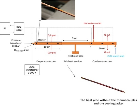
2.1. Test Rig
2.2. Preparation of the Working Fluid
- (1)
- Initially, the graphene nanoplatelets were weighted with a balancer. For 1 kg of n-pentane, the desired mass of graphene platelets was dispersed in n-pentane such that the nanofluids were prepared at weight percentages of 0.1, 0.2 and 0.3.
- (2)
- A magnetic stirrer was used to uniformly disperse the GNPs into n-pentane at stirring speed of 300 rpm for 10 minutes. However, due to the potential agglomeration of the nanoparticles, an ultrasonic homogenizer was employed at 350 Watt and frequency of 40 kHz for almost 10 minutes to crack the clusters and agglomerated particles.
- (3)
- To increase the stability of the nanoparticles, an anionic surfactant of nonyl phenol ethoxylate was added to the nano-suspensions and the nano-suspensions were stirred for 5 more minutes to uniformly disperse the surfactant inside the nano-suspension.
- (4)
- pH of the nano-suspensions was also regulated with a buffer solution to minimize the fouling formation within the system. A mixture of HCl and NaOH at 0.1 mM was employed.
- (5)
- Time-settlement experiments were employed to ensure about the stability of the nanofluids. To perform, nanofluids were placed inside the containers at various pH values and the sedimentation of the nanoparticles was constantly monitored to identify the best conditions in which the thickness of the sedimentation layer is minimized. Stability tests results illustrated that nanofluid could be stable for three weeks, which was sufficient for conducting the experiments.
2.3. Data Reduction
3. Results and Discussion
3.1. Temperature Profile
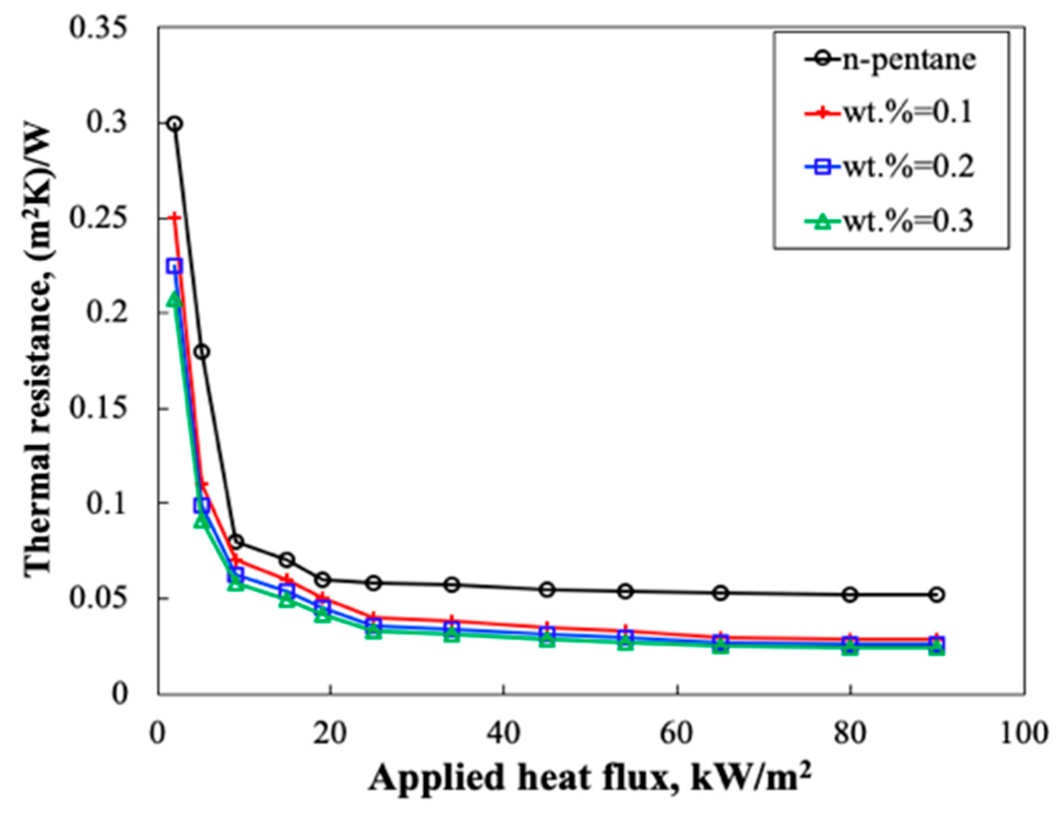
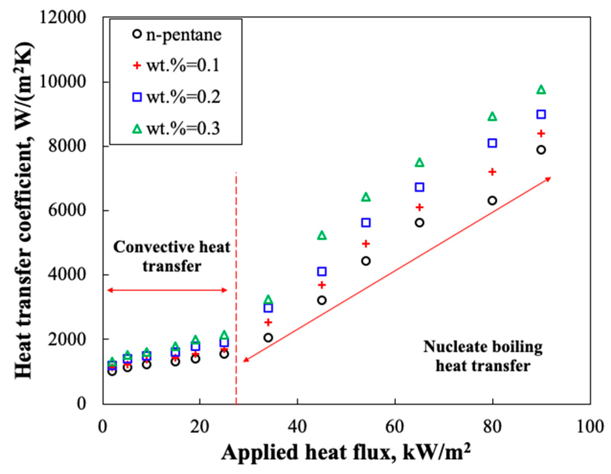
3.2. Effect of Heat Flux
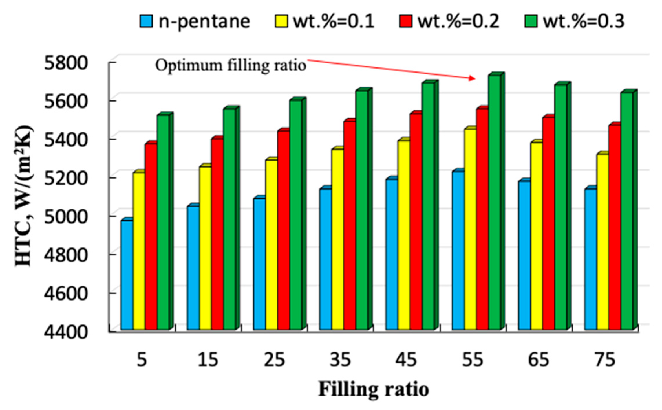
3.3. Filling Ratio
3.4. Installation Angle
4. Conclusions
Author Contributions
Funding
Acknowledgments
Conflicts of Interest
References
- Tsai, C.; Chien, H.; Ding, P.; Chan, B.; Luh, T.-Y.; Chen, P.-H. Effect of structural character of gold nanoparticles in nanofluid on heat pipe thermal performance. Mater. Lett. 2004, 58, 1461–1465. [Google Scholar] [CrossRef]
- Panwar, N.; Kaushik, S.; Kothari, S.; Panwar, D.N.L. Role of renewable energy sources in environmental protection: A review. Renew. Sustain. Energy Rev. 2011, 15, 1513–1524. [Google Scholar] [CrossRef]
- Dincer, I. Renewable energy and sustainable development: A crucial review. Renew. Sustain. Energy Rev. 2000, 4, 157–175. [Google Scholar] [CrossRef]
- Kreith, F.; Kreider, J.F. Principles of Solar Engineering; Hemisphere Publishing Corp.: Washington, DC, USA, 1978; p. 790. [Google Scholar]
- Tian, Y.; Zhao, C. A review of solar collectors and thermal energy storage in solar thermal applications. Appl. Energy 2013, 104, 538–553. [Google Scholar] [CrossRef]
- Olia, H.; Torabi, M.; Bahiraei, M.; Ahmadi, M.H.; Goodarzi, M.; Safaei, M.R. Application of Nanofluids in Thermal Performance Enhancement of Parabolic Trough Solar Collector: State-of-the-Art. Appl. Sci. 2019, 9, 463. [Google Scholar] [CrossRef]
- Kreider, J.F.; Kreith, F. Solar Energy Handbook; McGraw-Hill: New York, NY, USA, 1981. [Google Scholar]
- Arya, A.; Sarafraz, M.M.; Shahmiri, S.; Madani, S.A.H.; Nikkhah, V.; Nakhjavani, S.M. Thermal performance analysis of a flat heat pipe working with carbon nanotube-water nanofluid for cooling of a high heat flux heater. Heat Mass Transf. 2018, 54, 985–997. [Google Scholar] [CrossRef]
- Sarafraz, M.; Hormozi, F.; Peyghambarzadeh, S. Thermal performance and efficiency of a thermosyphon heat pipe working with a biologically ecofriendly nanofluid. Int. Commun. Heat Mass Transf. 2014, 57, 297–303. [Google Scholar] [CrossRef]
- Sarafraz, M.; Hormozi, F. Experimental study on the thermal performance and efficiency of a copper made thermosyphon heat pipe charged with alumina—Glycol based nanofluids. Powder Technol. 2014, 266, 378–387. [Google Scholar] [CrossRef]
- Sarafraz, M.; Pourmehran, O.; Yang, B.; Arjomandi, M. Assessment of the thermal performance of a thermosyphon heat pipe using zirconia-acetone nanofluids. Renew. Energy 2019, 136, 884–895. [Google Scholar] [CrossRef]
- Nakhjavani, M.; Nikkhah, V.; Sarafraz, M.; Shoja, S.; Sarafraz, M. Green synthesis of silver nanoparticles using green tea leaves: Experimental study on the morphological, rheological and antibacterial behaviour. Heat Mass Transf. 2017, 53, 3201–3209. [Google Scholar] [CrossRef]
- Nikkhah, V.; Sarafraz, M.; Hormozi, F. Application of spherical copper oxide (II) water nano-fluid as a potential coolant in a boiling annular heat exchanger. Chem. Biochem. Eng. Q. 2015, 29, 405–415. [Google Scholar] [CrossRef]
- Sarafraz, M.; Hormozi, F.; Peyghambarzadeh, S.; Vaeli, N. Upward Flow Boiling to DI-Water and Cuo Nanofluids Inside the Concentric Annuli. J. Appl. Fluid Mech. 2015, 8, 651–659. [Google Scholar]
- Sarafraz, M.; Hormozi, F.; Silakhori, M.; Peyghambarzadeh, S.M. On the fouling formation of functionalized and non-functionalized carbon nanotube nano-fluids under pool boiling condition. Appl. Therm. Eng. 2016, 95, 433–444. [Google Scholar] [CrossRef]
- Sarafraz, M.; Nikkhah, V.; Madani, S.; Jafarian, M.; Hormozi, F. Low-frequency vibration for fouling mitigation and intensification of thermal performance of a plate heat exchanger working with CuO/water nanofluid. Appl. Therm. Eng. 2017, 121, 388–399. [Google Scholar] [CrossRef]
- Sarafraz, M.; Nikkhah, V.; Nakhjavani, M.; Arya, A. Thermal performance of a heat sink microchannel working with biologically produced silver-water nanofluid: Experimental assessment. Exp. Therm. Fluid Sci. 2018, 91, 509–519. [Google Scholar] [CrossRef]
- Sarafraz, M.M.; Peyghambarzadeh, S.; Fazel, S.A.; Vaeli, N. Nucleate pool boiling heat transfer of binary nano mixtures under atmospheric pressure around a smooth horizontal cylinder. Period. Polytech. Chem. Eng. 2013, 57, 71–77. [Google Scholar] [CrossRef]
- Sarafraz, M.; Peyghambarzadeh, S.M. Nucleate pool boiling heat transfer to Al2O3-water and TiO2-water nanofluids on horizontal smooth tubes with dissimilar homogeneous materials. Chem. Biochem. Eng. Q. 2012, 26, 199–206. [Google Scholar]
- Yu, W.; France, D.M.; Routbort, J.L.; Choi, S.U.S. Review and comparison of nanofluid thermal conductivity and heat transfer enhancements. Heat Transf. Eng. 2008, 29, 432–460. [Google Scholar] [CrossRef]
- Li, Y.; Zhou, J.; Tung, S.; Schneider, E.; Xi, S. A review on development of nanofluid preparation and characterization. Powder Technol. 2009, 196, 89–101. [Google Scholar] [CrossRef]
- Kleinstreuer, C.; Feng, Y. Experimental and theoretical studies of nanofluid thermal conductivity enhancement: A review. Nanoscale Res. Lett. 2011, 6, 229. [Google Scholar] [CrossRef]
- Jang, S.P.; Choi, S.U.S. Role of Brownian motion in the enhanced thermal conductivity of nanofluids. Appl. Phys. Lett. 2004, 84, 4316–4318. [Google Scholar] [CrossRef]
- Prasher, R.; Bhattacharya, P.; Phelan, P.E. Brownian-motion-based convective-conductive model for the effective thermal conductivity of nanofluids. J. Heat Transf. 2006, 128, 588–595. [Google Scholar] [CrossRef]
- Malvandi, A.; Ganji, D.D. Brownian motion and thermophoresis effects on slip flow of alumina/water nanofluid inside a circular microchannel in the presence of a magnetic field. Int. J. Therm. Sci. 2014, 84, 196–206. [Google Scholar] [CrossRef]
- Shafahi, M.; Bianco, V.; Vafai, K.; Manca, O. Thermal performance of flat-shaped heat pipes using nanofluids. Int. J. Heat Mass Transf. 2010, 53, 1438–1445. [Google Scholar] [CrossRef]
- Naphon, P.; Khonseur, O. Study on the convective heat transfer and pressure drop in the micro-channel heat sink. Int. Commun. Heat Mass Transf. 2009, 36, 39–44. [Google Scholar] [CrossRef]
- Azari, A.; Derakhshandeh, M. An experimental comparison of convective heat transfer and friction factor of Al2O3 nanofluids in a tube with and without butterfly tube inserts. J. Taiwan Inst. Chem. Eng. 2015, 52, 31–39. [Google Scholar] [CrossRef]
- Abdollahi-Moghaddam, M.; Motahari, K.; Rezaei, A.; Abdollahi-Moghaddam, M.; Motahari, K.; Rezaei, A. Performance characteristics of low concentrations of CuO/water nanofluids flowing through horizontal tube for energy efficiency purposes; an experimental study and ANN modeling. J. Mol. Liq. 2018, 271, 342–352. [Google Scholar] [CrossRef]
- Nazari, M.A.; Ghasempour, R.; Ahmadi, M.H.; Heydarian, G.; Shafii, M.B. Experimental investigation of graphene oxide nanofluid on heat transfer enhancement of pulsating heat pipe. Int. Commun. Heat Mass Transf. 2018, 91, 90–94. [Google Scholar] [CrossRef]
- Togun, H.; Ahmadi, G.; Abdulrazzaq, T.; Shkarah, A.J.; Kazi, S.N.; Badarudin, A.; Safaei, M.R. Thermal performance of nanofluid in ducts with double forward-facing steps. J. Taiwan Inst. Chem. Eng. 2015, 47, 28–42. [Google Scholar] [CrossRef]
- Kline, S.J.; McClintock, F.A. Describing Uncertainties in Single-Sample Experiments. Mech. Eng. 1953, 75, 3–8. [Google Scholar]
- Kline, S. The purposes of uncertainty analysis. J. Fluids Eng. 1985, 107, 153–160. [Google Scholar] [CrossRef]
- Faghri, A. Heat pipes: Review, opportunities and challenges. Front. Heat Pipes 2014, 5. [Google Scholar] [CrossRef]
- Naphon, P.; Thongkum, D.; Assadamongkol, P. Heat pipe efficiency enhancement with refrigerant—Nanoparticles mixtures. Energy Convers. Manag. 2009, 50, 772–776. [Google Scholar] [CrossRef]


© 2019 by the authors. Licensee MDPI, Basel, Switzerland. This article is an open access article distributed under the terms and conditions of the Creative Commons Attribution (CC BY) license (http://creativecommons.org/licenses/by/4.0/).
Share and Cite
Sarafraz, M.M.; Tlili, I.; Tian, Z.; Bakouri, M.; Safaei, M.R.; Goodarzi, M. Thermal Evaluation of Graphene Nanoplatelets Nanofluid in a Fast-Responding HP with the Potential Use in Solar Systems in Smart Cities. Appl. Sci. 2019, 9, 2101. https://doi.org/10.3390/app9102101
Sarafraz MM, Tlili I, Tian Z, Bakouri M, Safaei MR, Goodarzi M. Thermal Evaluation of Graphene Nanoplatelets Nanofluid in a Fast-Responding HP with the Potential Use in Solar Systems in Smart Cities. Applied Sciences. 2019; 9(10):2101. https://doi.org/10.3390/app9102101
Chicago/Turabian StyleSarafraz, M. M., Iskander Tlili, Zhe Tian, Mohsen Bakouri, Mohammad Reza Safaei, and Marjan Goodarzi. 2019. "Thermal Evaluation of Graphene Nanoplatelets Nanofluid in a Fast-Responding HP with the Potential Use in Solar Systems in Smart Cities" Applied Sciences 9, no. 10: 2101. https://doi.org/10.3390/app9102101
APA StyleSarafraz, M. M., Tlili, I., Tian, Z., Bakouri, M., Safaei, M. R., & Goodarzi, M. (2019). Thermal Evaluation of Graphene Nanoplatelets Nanofluid in a Fast-Responding HP with the Potential Use in Solar Systems in Smart Cities. Applied Sciences, 9(10), 2101. https://doi.org/10.3390/app9102101