1. Introduction
Following the detection of gravitational waves by the LIGO (Laser Interferometer Gravitational-wave Observatory) [
1], detecting such waves at lower frequencies is the next exciting scientific challenge for the coming decade [
2]. The LISA (Laser Interferometer Space Antenna) mission, proposed by ESA (European Space Agency) and with contributions by NASA (National Aeronautics and Space Administration), is the earliest and most mature plan to study gravitational waves in the frequency band between 0.1 mHz and 1 Hz [
3,
4]. The LISA mission with its three satellites will use heterodyne interferometry to convert the tiny displacements between test masses into a phase fluctuation in the interferometric signal. The length of the interferometer arms that are formed by LISA’s satellites is 2.5 million kilometers [
5]. About two months before LIGO announced the first detection of gravitational waves, the LISA pathfinder was launched into space for technical validation [
6,
7]. After successful tests of the LISA pathfinder, the LISA mission is scheduled to be launched in the year 2034 [
7,
8]. Similar to LISA, the Taiji space gravitational wave detection, the length of the interferometer arm being 3 million kilometers, initiated by Chinese Academic of Sciences in 2008, plans to be launched in 2033 [
9]. A pathfinder mission is planned to validate all key technologies prior to the Taiji mission [
10,
11,
12].
In assembling the optical bench of Taiji and its pathfinder, an optical bonding technology is expected to be adopted in joining the optical components with their substrates [
13,
14,
15]. The hydroxide-catalysis bonding [
13], which has been successfully applied in the Gravity Probe B mission and the LISA pathfinder [
16], was chosen for joins in the optical bench for the Taiji and its pathfinder mission. Different from the traditional epoxy glue, the hydroxide-catalysis bonding forms covalent bonds between materials through hydration and hydrolysis. There is no additional material layer formed during the bonding process, and therefore satisfies the special requirements of the Taiji pathfinder, such as structural strength, reliability, and extreme thinness of the adhesive layer.
For principle verification for the Taiji pathfinder mission, an optical bench was built employing the hydroxide-catalysis bonding and tested in our laboratory. In this paper, the optical layout of the interferometer is given in
Section 2. Next, the adjustment strategy of the optical bench assembly is presented in
Section 3. Details of the hydroxide-catalysis bonding and assembly process are given in
Section 4 and
Section 5. Finally, the noise performance of the optical bench is given in
Section 6.
2. Optical Layout
A prototype of the optical bench was built to help in the optimization of the hydroxide-catalysis bonding and in determining the precision of the optical assembly. As shown in
Figure 1 (this figure was created using the component library by Alexander Franzen, Albert Einstein Institution, Hannover, Germany, 2017), the optical layout of the interferometer includes a simple Mach–Zehnder interferometry system. A laser beam from a frequency-stabilized laser (wavelength: 1064 nm, linear polarized, and single mode) is split by a 50/50 BS (Beam Splitter). The transmitted beam directly accesses an AOM (Acoustic-Optical Modulator), whereas the reflected beam accesses another AOM after a reflector changes its direction of propagation. Both beams are frequency shifted by the AOMs, and the difference between the modulated values is the frequency of the heterodyne interferometric signal. Next, these two beams are coupled into a single-mode polarization-maintaining fiber and sent into the interferometry system. The interference system is located in the vacuum chamber to reduce the influence of air disturbance on the measurement precision. The interferometer contains two FCPSs (Fiber Collimation Package Subassemblies) for beam collimating, two BSs and two BCs (Beam Combiners), which perform the interferometry. Two PDs (Photo-Detectors) convert the optical signals into electric signals. Finally, the phase information of the electric signals from the PDs are obtained using a phasemeter.
3. Adjustment Strategy
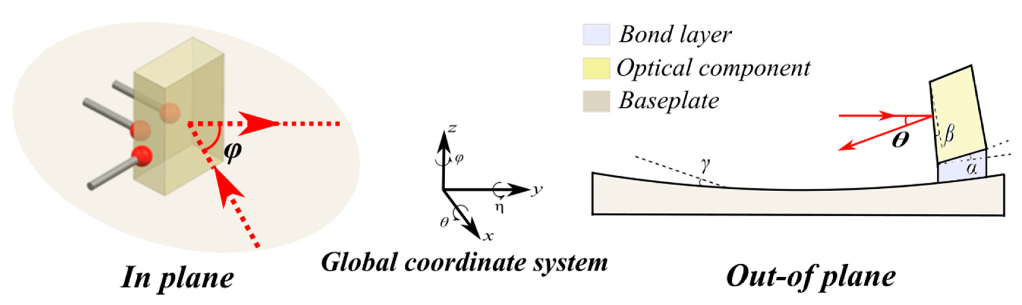
Ideally, in the global coordinate system of the assembly (
Figure 2), the incident and the reflected beams (red dash line) only propagate in the plane of the interferometer (the designated X-Y plane) and parallel to the bonding surface, and establishes the "in-plane" [
17]. Hence, if we adjust the "in-plane" angle of propagation, we only need to adjust angle φ. In accordance with the principle of kinematic constraint, the adjustment of the three degrees of freedom (x, y, φ) in the "in-plane" can be accomplished using three points (
Figure 2). For high adjustment precision, a large-stroke hexapod (Model P84, Core Tomorrow, Harbin, China) is used to manipulate the position of the target. The displacement and angular precision of the piezoelectric actuators are ±7 nm and ±0.5 μrad, respectively.
However, the bottom plane of the optical components and the baseplate are not always ideal planes. In this situation (
Figure 2), “out-of-plane” refers to the beam position evolution in the
z and
degrees of freedom, which is mainly caused by the following three parts:
(1) The surface shape of the baseplate exhibits a shape of an approximate sinusoidal curve [
18] with a flatness of λ/4 (peak-to-valley, ~160 nm, λ = 632.8 nm). For an optical element with 10 mm thickness, the maximum value γ of the angular error introduced thereby is about ±5 μrad.
(2) The thickness of the glue layer introduced by the hydroxide-catalysis bonding process is about a hundred nanometers order. The non-uniform distribution of the adhesive will cause the unnecessary surface tilt α. The value is about ±10 μrad.
(3) For the limitation of the optical lens processing, the parallelism between two optical surfaces is about 10 μrad.
Therefore, the are obtained using the manufacturing tolerances () together with the uniform bond layer thickness (), and this degree of freedom is uncontrolled in the assembly process. For those values, an additional “out-of-plane” error is actually present of about 5~30 μrad.
4. Hydroxide-Catalysis Bonding
Given the successful experience with the LISA pathfinder, the Taiji program adopted hydroxide-catalysis bonding technology for the assembly of its interferometer [
13,
19]. To improve reliability, the bonding process must be completed in a Class 100 clean room, and the flatness of the component bonding surface must be within a tolerance of λ/10 (~60 nm, λ = 632.8 nm). The adhesive solution is prepared by diluting 14% NaOH and 27% SiO
2 silicate solution with deionized water in a ratio of 1:6.
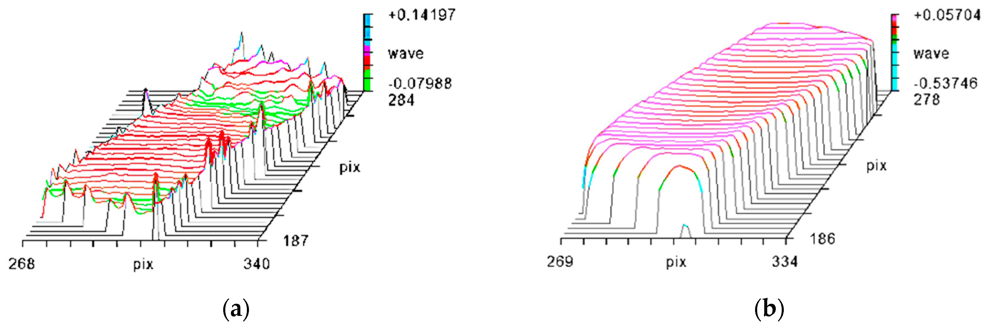
With processing limitations, there is a certain amount of burring (~90 nm) of the edge of the component bonding (bottom) surface, which influences the effectiveness of bonding. Therefore, we need to re-polish the component with cerium oxide before bonding. A laser interferometer (ZYGO) was used to make an image comparison of the surface of optical components before and after polishing. Because the surface changes of optical elements before and after polishing are basically the same, we arbitrarily select a group of comparison results. As shown in
Figure 3, the polishing has clearly removed the peripheral burrs.
After ensuring the bonding environment and the flatness of the component surface, the bonding process can be divided into the following five steps:
1) Component Cleaning: every component was cleaned using an ultrasonic cleanser with a suitable cleaning solution to increase the hydrophilicity of the bonding surface after polishing.
2) Smear the transition solution and adjustment: when the optical element is adjusted on the baseplate, slow volatilization and low residual octane was used as a transitional solution between the two surfaces to avoid direct contact between the optical surfaces.
3) Smear Adhesives: when the component is adjusted to its ideal position, the transitional solution is replaced by the bonding solution, and then the optical component is returned.
4) Micro Adjustment: as the adhesive takes about 100 s to cure, minute adjustments of the optical element are still possible during this period.
5) Curing after alignment: The beam alignment needs to be completed as quickly as possible within 100s, otherwise we need to repeat the above process for re-bonding. After bonding, it needs to be cured at room temperature for one week to have sufficient bonding strength between the components and the baseplate [
19].
5. Assembly
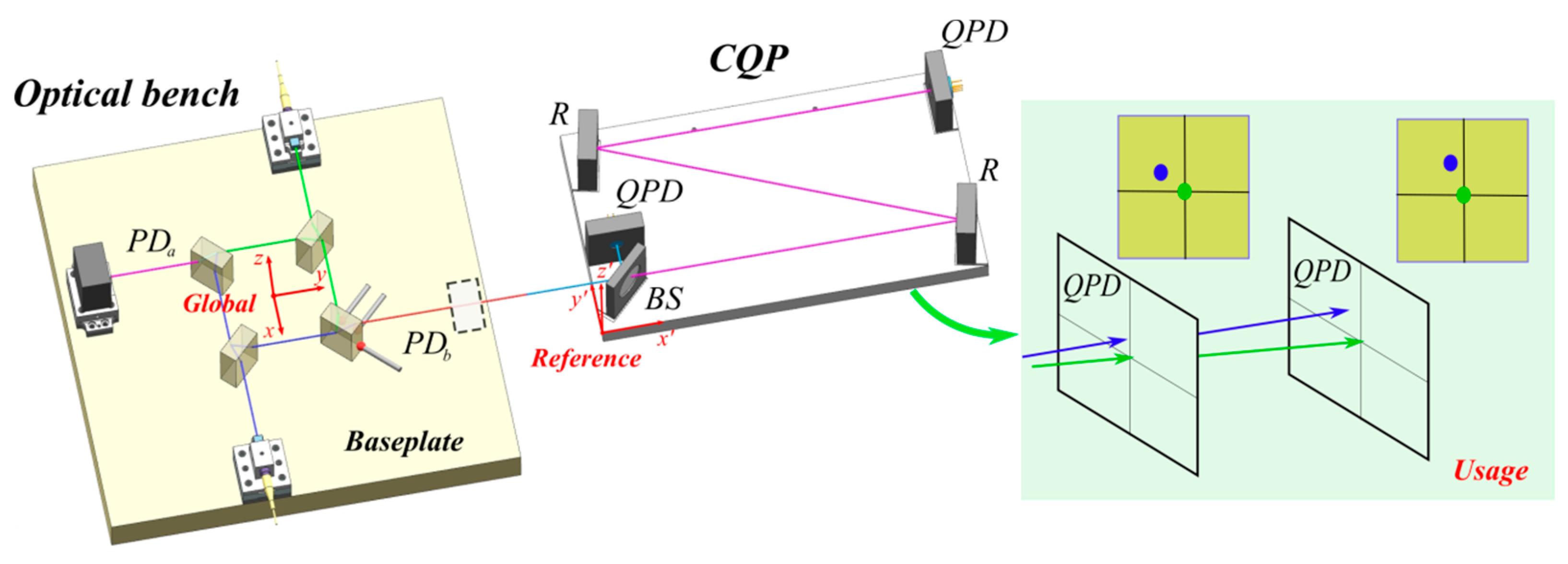
The nominal optical layout has perfectly matched paths, but constructing an interferometer without path mis-match is difficult. In the process of assembly, the precise position of the beam is first measured, so that the position of the optical element can be adjusted by the beam position. The measurement of the beam requires a CQP (Calibrated Quadrant-photodiode Pair) device (
Figure 4) [
20]. The CQP is an auxiliary measuring equipment, which consists of a BS, two reflectors, and two quadrant photodiodes (QPDs). The measurement principle of the CQP is to determine the unique straight line through two QPDs. If a beam passes through the centers of the two QPDs, a particular set of position parameters exists with the CQP, i.e. the incident point and the directional vector of the beam are constant in value in the CQP reference coordinate system. After calibrated [
20], the position parameters under the reference coordinate system is known and can be converted to the global coordinate system by means of Coordinate Measuring Machine (CMM). Because of the measurement precision of CMM (1.5 μm + 1 μm/m) and the fitting error of parameters, the measurement precision of the position parameters under the global coordinate system is ±5 μm, ±30 μrad.
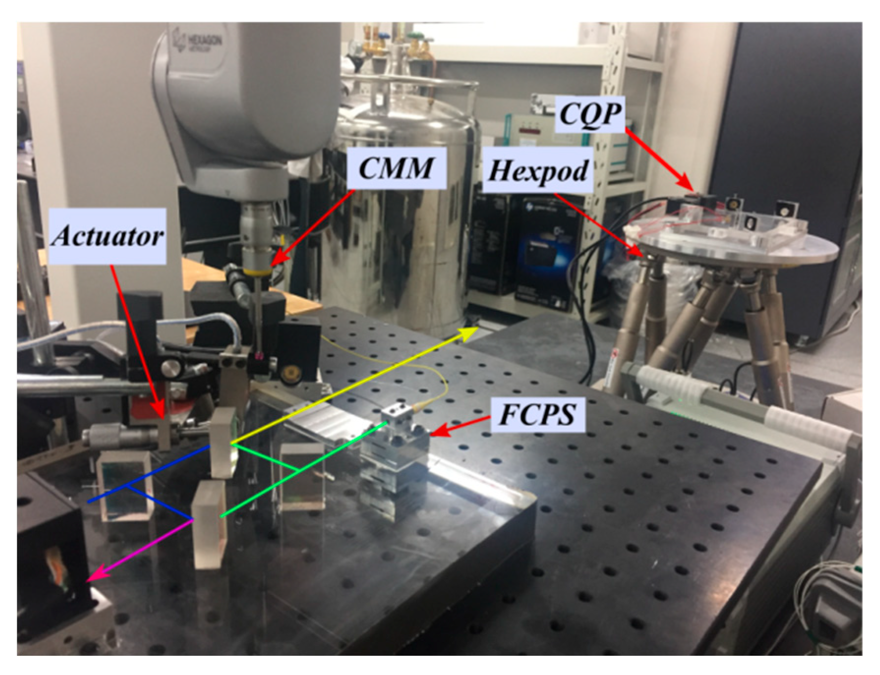
In the alignment process (
Figure 5), the FCPS of the interference system acts as a light source to provide a stable and collimated Gaussian beam, which is directed into the starting position of the interferometer. Because of influences from pre-assembly and measurement errors, the beams may show large deviations once the components are directly positioned in their geometric model positions. The specific operation procedure for the FCPS assembly is the following: (a) First, the CQP pose is adjusted using the hexapod platform to ensure the beam passes through the center of the two QPDs. (b) Second, with the aid of the CQP, the absolute position of the beam in the global coordinate system is read by the CMM. (c) Finally, the position of the FCPS is adjusted iteratively until the exiting light reaches the desired position. Then, the location of the BS and BC are determined in the same way.
After curing the optical element, the deviation of the position parameters between the theoretical beam and the measured beam (the absolute deviation of the beam itself) of the two interference positions under the global coordinate system is re-measured using the CMM with CQP. The results show that compared to theoretical position at the PDa, the position and angle (directional vector sum of "in-plane" and "out-of-plane") of deviation of the two beams are 3 μm, 18 μrad and 9 μm, 42 μrad, respectively; the corresponding result for the deviation at the PDb is 5 μm, 30 μrad and 10 μm, 45 μrad, respectively. Finally, PDa and PDb are fixed in suitable positions so that the energy of the two interference beams on the PD is not clipped.
Based on the above data, the relative positional deviation at PD
a and PD
b are 6 μm and 5 μm, and the angular deviation are 24 μrad and 15 μrad, respectively. Unlike the relative deviation between the beams, the absolute deviation will result in a relative path length difference between the interferometer PD
a and the interferometer PD
b, which will affect the final interferometric precision [
20]. The relative position deviation between beams mainly affects the interference contrast, i.e., the difficulty of signal extraction.
6. Results and Discussion
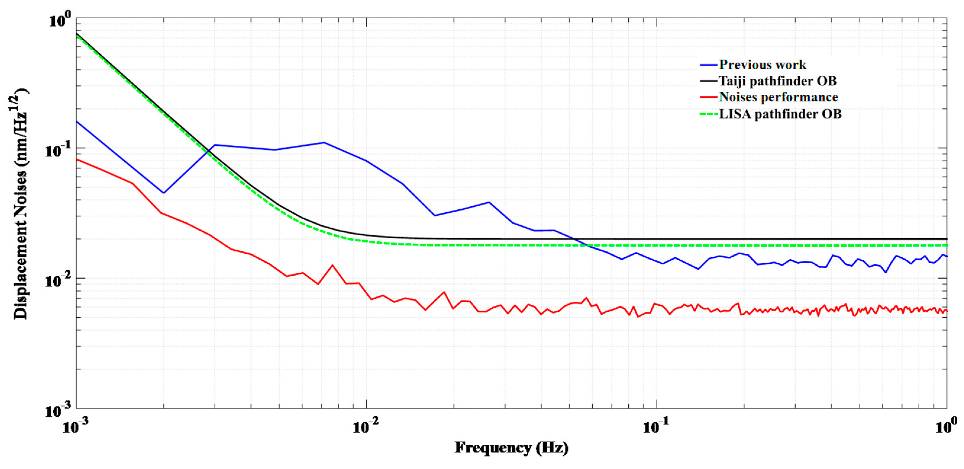
After assembly, the demonstration interferometer was tested in a vacuum chamber at 22 ± 0.1 °C temperature. The noise performance is shown in
Figure 6.
The sensitivity of the interferometer reaches 6 pm/√Hz in the frequency band from 0.03 Hz to 1 Hz. Compared with our previous result [
12], the noise has largely decreased because the difference in relative path length between the PD
a and PD
b interferometers has decreased with the equipment being precisely positioned. In the case of frequency noise, it is the relative path length difference between the PD
a and PD
b interferometers which is important, i.e. that the frequency noise signal at the PD
a interferometer is the same as that of a PD
b interferometer such that it can be subtracted out as a common mode signal [
22]. Among them, unequal arm lengths
of the interferometer due to assembly errors will couple frequency noise
as noise in the displacement measured, which can be expressed as [
23]:
where is the frequency of the laser; the laser wavelength is 1064 nm, and the frequency noise of the laser used is about 1 MHz/√Hz in this experiment. In our previous research, the interferometer system was based on individual opto-mechanical components with a clamping structure. The positioning precision was about 0.5~1 cm, the difference in the arm lengths also being about 1 cm. Therefore, the theoretical value of the noise from frequency jitter is about 35 pm/√Hz. Considering the estimated error of , it is reasonable that the final tested result is 15 pm/√Hz, where the dominant noise is from frequency jitter. From the optical bonding and precision positioning technology, the relative path length difference between the two interferometers is mainly affected by the manufacturing error of the optical components, which was reduced to less than 0.5 mm in the demonstration optical bench. Therefore, the frequency jitter noise, which in our previous result was the dominant noise from the frequency source, is theoretically less than 2 pm/√Hz in this current setup.
Because of thermal drift, the sensitivity curve is slightly higher for frequencies below 0.03 Hz, but its value is still lower than the specifications for the Taiji pathfinder. In addition, compared to the previous experiment, the noise of this experiment decreased more seriously in the frequency band from 0.003 Hz to 0.03 Hz. That is, the hydroxide-catalysis bonding is an effective way to reduce the adhesive stress and internal stress of the optical components. Therefore, under our laboratory conditions, the related thermal deformation of the optical components and baseplate has also decreased.
7. Conclusions and Outlook
An ultraprecise demonstration optical bench was constructed and tested for the Taiji pathfinder mission. With the precise positioning of the equipment, the angular deviation from the theoretical beam in the two end PDs of the interferometer were found to be less than 42 μrad and 45 μrad, and their deviation in position were 9 μm and 10 μm, respectively. Compared with our previous results, the sensitivity of this optical bench reached 6 pm/√Hz in the frequency band from 0.03 Hz to 1 Hz, thus representing a significant improvement. This was because the noise from frequency jitter decreased considerably as a result of the precision positioning technology and the use of better optical bonding. The frequency jitter in the laser beam has therefore been largely suppressed in this optical bench. Although the demonstration system has been constructed and tested, the optical bench of the Taiji pathfinder is much more complex. Moreover, its mechanical and thermal reliability, which must satisfy environmental simulation tests of the Taiji pathfinder space flight, remains to be verified.

