Article

Coupled Dual-Loop Optoelectronic Oscillator Based on Stimulated Brillouin Scattering

School of Optoelectronic Engineering and Instrumentation Science, Dalian University of Technology, Dalian 116024, China
*
Author to whom correspondence should be addressed.
Appl. Sci. 2019, 9(10), 2077; https://doi.org/10.3390/app9102077
Submission received: 12 April 2019 / Revised: 14 May 2019 / Accepted: 16 May 2019 / Published: 20 May 2019
(This article belongs to the Section Optics and Lasers)

Abstract

:
A tunable optoelectronic oscillator (TOEO) with coupled dual-loop (CDL) based on stimulated Brillouin scattering (SBS) is proposed. In our scheme, the CDL is constructed by cascading a dual-output Mach–Zehnder intensity modulator (DOMZM) and a single output Mach–Zehnder intensity modulator (MZM). One optical output of the DOMZM is directly injected to the MZM, and the other optical output of the DOMZM is transformed into microwave signals to modulate the MZM. The narrow gain spectrum of SBS is used to select the oscillation frequency and realize frequency tunability. By joining the CDL, we can not only increase side mode suppression ratio (SMSR) and decrease phase noise, but also improve stability of the TOEO. Experimental results show that microwave signals from 2 GHz to 18 GHz with the SMSR as high as 60 dB and the phase noise as low as −95 dBc/Hz at 10 kHz frequency offset are achieved. Furthermore, the frequency drift is less than 0.3 ppm and the power drift is lower than 0.2 dB at 10 GHz within 30 min in lab condition.

1. Introduction

An optoelectronic oscillator (OEO) as a new type of microwave signal source, can generate high-quality microwave signals of tens or even hundreds of GHz [1]. It can be applied in many fields to improve the performance of electronic systems, such as radar [2], communication [3], remote sensing and telemetry [4]. The microwave signals generated by the OEO have low phase noise, high spectral purity and a quality factor. In the early research on OEO, a fixed center frequency bandpass filter was used as the frequency selective device to realize microwave signal generation, but this method would limit the tunability of the OEO and only generate a fixed frequency microwave signal. In order to generate frequency tunable microwave signals, many tunable optoelectronic oscillator (TOEO) schemes have been proposed [5,6,7,8]. Common to these schemes is the introduction of a microwave photonic bandpass filter (MPBF) into the OEO, which utilizes the MPBF for frequency selection and frequency tunability. In [5], the MPBF is formed by an injection-locked Fabry–Perot laser diode (FP-LD) that realizes frequency tuning by adjusting the cavity length or the wavelength of the incident light. This solution enables microwave signal generation with a frequency tuning range of 6.41 to 10.85 GHz. However, the stability of the microwave signals generated by the FP-LD are poor. In [6], the MPBF is implemented by a polarization beam splitter (PBS), chirped fiber Bragg grating (CFBG) and a polarization modulator. Frequency tuning can be obtained by adjusting the polarization before the PBS using a polarization controller (PC), which can obtain microwave signals from 5.8 to 11.8 GHz. However, the PC is sensitive to both temperature and environmental vibrations, thus resulting in microwave signal instability. In [7], the MPBF is structured by cascading two phase modulators (PM) and a phase-shifted fiber Bragg grating (PS-FBG). The narrow notch of PS-FBG suppresses the sideband of phase modulation to realize conversion between phase modulation and intensity modulation. The tunability of the microwave signals can be achieved by changing the wavelength interval between the optical carrier and the notch of PS-FBG. The scheme achieves a wide tunability from 3 to 28 GHz, but the PS-FBG is also sensitive to environmental fluctuations, and it is difficult to generate stable microwave signals. In [8], the MPBF is realized by a very simple method that a phase modulator is directly connected with an optical bandpass filter (OBPF) to realize the phase modulation to the intensity modulation conversion. A large range of microwave signals is generated from 4.74 to 38.38 GHz, but this method requires an OBPF with a very narrow passband width. The OBPF is a complicated instrument and difficult to apply in practice.
Stimulated Brillouin scattering (SBS) is also considered as an MPBF solution with great potential because it can be integrated into photonic chips [9,10]. The link research of SBS-based TOEO is significant for SBS integrated on photonic chips, which can guide the link structure of the integrated SBS chips. The SBS-based TOEO needs many improvements in side mode and stability. A variety of methods have been proposed for improving performance of OEO [11,12,13,14,15,16,17,18,19,20,21]. In [11,12,13,14], the researchers increase the side mode suppression ratio (SMSR) by multi-loop structure. In [15], a dual-loop SBS-based TOEO have been proposed and the SMSR is only 35 dB at 10 GHz. An improved SBS-based TOEO has been researched and the SMSR is increased to 45 dB at 10 GHz by employing a polarization multiplexed dual-loop in [16]. However, the scheme still has a high side mode for a high-quality microwave signal and needs to be improved. In fact, the SBS-based TOEOs also have a problem with the stability of frequency and power. The microwave signal generated in the scheme [15,16] is easy to hop or multi-mode oscillate. In order to improve the stability of OEO, numerous schemes have been proposed [17,18,19,20,21]. The mainly frequency stabilization techniques contain a phase-locked loop [17,18,19] and thermal control [20,21]. The phase-locked method requires an external reference signal to the loop of OEO, and the reference signal affects the phase noise of the oscillation signal. The thermal control method requires that all the thermally sensitive devices must be placed in a constant temperature system, which is difficult to realize in practical applications. A stability improved SBS-based TOEO has been designed in [22], and the maximum power and frequency drift at 10.69 GHz are about 1.4 dB and 1 ppm in the case of testing for 1000 s.
In this paper, a TOEO with coupled dual-loop (CDL) based on SBS is theoretically analyzed and experimentally demonstrated. In our scheme, the CDL is constructed by cascading two modulators, a dual-output Mach–Zehnder intensity modulator (DOMZM) and a single output Mach–Zehnder intensity modulator (MZM). One optical output of the DOMZM is directly injected to MZM, and the other optical output of the DOMZM is transformed into a microwave signal to modulate the MZM. The narrow gain spectrum of SBS is employed to choose the oscillation frequency and realize tunability. By joining the CDL, we not only increase SMSR and lower phase noise, but also enhance stability of the generated microwave signal. In the experiment, high-quality microwave signals with a widely tunable range from 2 to 18 GHz are generated. When the oscillation frequency is chosen as 5, 10, or 15 GHz, the phase noise is as low as −95 dBc/Hz at 10 kHz frequency offset and the SMSR is superior to 60 dB. The frequency drift is less than 0.3 ppm and the power drift is lower than 0.2 dB during 30 min in lab condition, which confirms a relatively higher stability. To verify the advantage of CDL design, we also built a single loop SBS-based TOEO by disconnecting the CDL. Comparing with the single loop SBS-based TOEO, the proposed TOEO can improve the SMSR of 57 dB, the phase noise of 15.2 dB at 10 kHz offset, and effectively avoid frequency hopping or multi-mode oscillation.

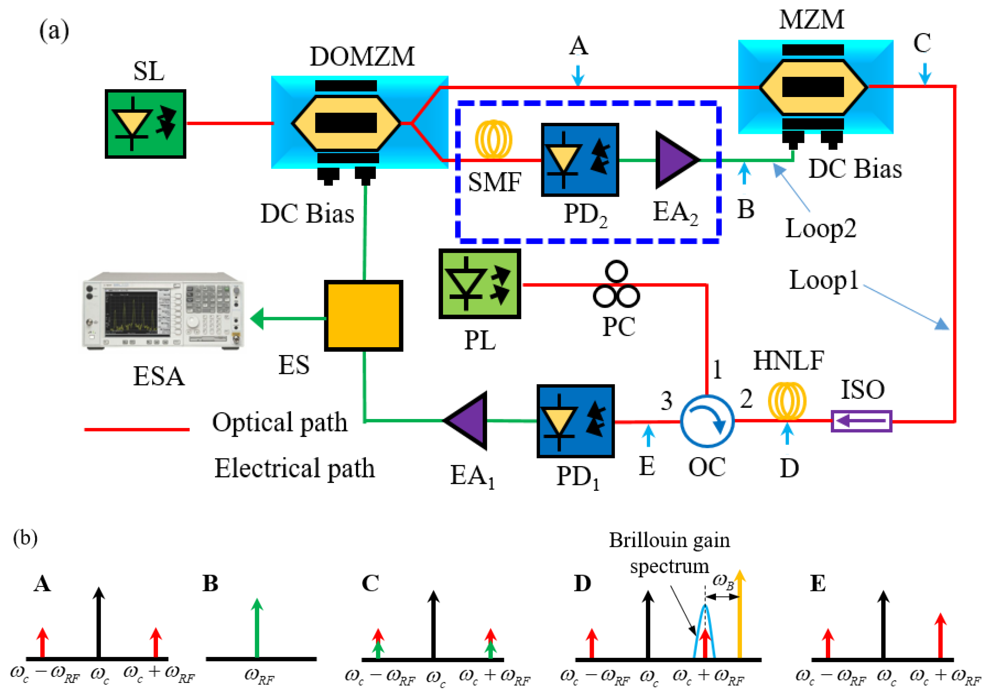
2. Principle of Operation

The schematic diagram of the coupled dual-loop SBS-based TOEO is shown in Figure 1a. The TOEO consists of a signal laser (SL), a dual-output Mach–Zehnder intensity modulator (DOMZM), a single-mode fiber (SMF), two photodetectors (PD), a single output Mach–Zehnder intensity modulator (MZM), an optical isolator (ISO), a polarization controller (PC), an optical circulator (OC), a high non-linear fiber (HNLF), two electrical amplifier (EA), an electrical splitter (ES). A light wave from the SL is sent to the DOMZM, which has two optical output terminals. One optical output of the DOMZM is directly sent to the MZM, and the other optical output of the DOMZM passes through the SMF and is transformed into microwave signal by PD2. Then the microwave signal modulates the MZM. The optical output of the MZM passes through the HNLF and then the reverse pump light stimulates the optical output of the MZM. After being filtered and amplified by the SBS gain spectrum, the optical output of the OC is injected into the PD1. Then, the microwave output of PD1 modulates the DOMZM to realize a closed loop after amplification by the EA1. The ES is placed between the EA1 and the DOMZM to separate part of the oscillating signal for measurement.
In order to clearly understand the principle of the coupled dual-loop SBS-based TOEO, we firstly explain the spectrums at different points of the TOEO. The schematic diagram of spectrums is shown in Figure 1b. The point A shows the double sideband optical signal of the DOMZM. The point B shows the microwave signal of the PD2 to modulate the MZM. The point C shows the double sideband optical signal of the MZM after modulating by the microwave signal of PD2. The point D shows the filtered and amplified process of SBS. The point E is the result after SBS processing. Then the optical signal is sent to the PD1 after SBS processing. When the loop gains over the oscillating threshold of the TOEO, the oscillation mode will be stably established.
Assuming that the DOMZM is modulated by:
V 1 ( t ) = V D C 1 + V R F 1 cos ( ω m t )
where V D C 1 is the bias voltage applied to the DOMZM, V R F 1 is the amplitude of the oscillating signal and ω m is the angular frequency of the oscillating signal. The DOMZM is set in the quadrature point so the V D C 1 is set to 0. The output optical field of the DOMZM, under a condition of small signal modulation, can be written as:
E D O M Z M ( t ) = 1 2 E 0 exp ( j ω 0 t ) [ exp ( j π V 1 ( t ) 2 V π 1 ) + j exp ( j π V 1 ( t ) 2 V π 1 ) ]
where E 0 is the amplitude of the input optical signal of the DOMZM and ω 0 is the angular frequency of the input optical signal of the DOMZM. V π 1 is the half-wave voltage of the DOMZM. Then the Equation (2) can be expanded with Bessel functions:
E D O M Z M ( t ) 2 2 E 0 { J 0 ( β 1 ) exp j ( ω 0 t + π 4 ) + J 1 ( β 1 ) exp j [ ( ω 0 + ω m ) t + π 4 ] + J 1 ( β 1 ) exp j [ ( ω 0 ω m ) t + π 4 ] }
where β 1 = π V R F / 2 V π 1 . J 0 ( β 1 ) is the zero-order Bessel functions of the first kind. J 1 ( β 1 ) is the first-order Bessel functions of the first kind. Then, one optical output of the DOMZM is directly sent into the MZM while the other optical output of the DOMZM is converted into microwave signal by the PD2 after passing through the SMF. The output V 2 ( t ) of the PD2 is proportional to | E D O M Z M ( t + τ 2 ) | 2 . τ 2 is the time delay introduced by Loop2. According to Equation (3), ignore the higher order terms, V 2 ( t ) can be described as:
V 2 ( t ) 2 R 2 G E A 2 E 0 2 J 0 ( β 1 ) J 1 ( β 1 ) exp [ j ( ω m t + ω m τ 2 + π 4 ) ]
where R 2 is the responsivity of the PD2, G E A 2 is the gain of the EA2. Then the microwave signal V 2 ( t ) of the PD2 can be applied to the MZM. The output optical field of the MZM can be expressed as:
E M Z M ( t ) = 2 2 E D O M Z M ( t ) + 2 2 E D O M Z M ( t ) exp { j π V π 2 V D C 2 + j π V π 2 R 2 G E A 2 E 0 2 J 0 ( β 1 ) J 1 ( β 1 ) exp [ j ( ω m t + ω m τ 2 + π 4 ) ] }
where V D C 2 is the bias voltage applied to the MZM, V π 2 is the half-wave voltage of the MZM. The bias voltage of MZM is set to V π / 2 . The reversed pump light stimulated the output optical signal of the MZM after passing through the HNLF. After processing by the SBS gain spectrum, the optical signals are sent into the PD1. Thus, ignoring the frequency-doubling signal and DC term, the output of the PD1 can be simply described as:
V 1 ( t ) R 1 E 0 2 2 { [ J 0 ( β 1 ) J 0 ( β 2 ) + J 0 ( β 1 ) J 0 ( β 3 ) ] exp ( j ω m t ) + [ J 0 ( β 1 ) J 1 ( β 2 ) + J 0 ( β 1 ) J 1 ( β 3 ) ] exp [ j ω m ( t + τ 2 ) ] } = R 1 E 0 2 2 { [ J 0 ( β 1 ) J 0 ( β 2 ) + J 0 ( β 1 ) J 0 ( β 3 ) ] + [ J 0 ( β 1 ) J 1 ( β 2 ) + J 0 ( β 1 ) J 1 ( β 3 ) ] exp ( j ω m τ 2 ) } exp ( j ω m t )
where β 2 = π V π 2 R 2 G E A 2 G B E 0 2 J 0 ( β 1 ) J 1 ( β 1 ) , β 3 = π 2 V π 2 R 2 G E A 2 G B E 0 2 J 1 ( β 1 ) J 1 ( β 1 ) . G B is the optical field gain of the SBS. R 1 is the responsivity of the PD1.
When the coupled dual-loop is closed and the loop gain over the oscillating threshold, the TOEO will begin to oscillate. The output signal by PD1 is the sum of all the cycles in the loop. If the oscillation mode stably established, the output electric field of PD1 can be written as:
V 1 ( t ) exp [ j [ ω m ( t + n τ 1 ) ] ] n = 0 { G E A 1 R 1 E 0 2 2 [ [ J 0 ( β 1 ) J 0 ( β 2 ) + J 0 ( β 1 ) J 0 ( β 3 ) ] + J 0 ( β 1 ) J 1 ( β 2 ) exp ( j ω m τ 2 ) + J 0 ( β 1 ) J 1 ( β 3 ) exp ( j ω m τ 2 ) ] } n = exp ( j ω m t ) n = 0 { exp ( j ω m n τ 1 ) [ G e ( ω m τ 2 ) ] n }
where G E A 1 is the gain of EA1, n is the number of oscillating times around the OEO loop and G e ( ω m τ 2 ) is called effective open-loop gain, written as:
G e ( ω m τ 2 ) = { G E A 1 R 1 E 0 2 2 [ [ J 0 ( β 1 ) J 0 ( β 2 ) + J 0 ( β 1 ) J 0 ( β 3 ) ] + J 0 ( β 1 ) J 1 ( β 2 ) exp ( j ω m τ 2 ) + J 0 ( β 1 ) J 1 ( β 3 ) exp ( j ω m τ 2 ) ] }
From Equation (9) we can find that the effective open-loop gain G e ( ω m τ 2 ) is not a constant but a sinusoidal function of ω m τ 2 , it means that the G e ( ω m τ 2 ) is a sinusoidal comb filter and the microwave signal is selective amplified. Thus, the frequency transfer function will be the product of the sinusoidal comb-filtering spectrum and SBS gain spectrum. When the TOEO stably oscillate, the effective open-loop gain G e ( ω m τ 2 ) is a little less than at oscillating threshold, and Equation (8) can be described as:
V 1 ( t ) exp ( j ω m t ) 1 G e ( ω m τ 2 ) exp ( j ω m τ 1 )
The corresponding microwave power P ( ω m , t ) with stable oscillation is then given:
P ( ω m , t ) | V 1 ( t ) | 2 2 R = 1 2 R [ 1 + G e 2 ( ω m τ 2 ) 2 G e ( ω m τ 2 ) cos ( ω m τ 1 ) ]
where R is the load impedance of PD1. The oscillation frequency must satisfy the loop phase matching condition and SBS frequency matching condition as:
{ ω m = 2 k π τ 1 k = 0 , 1 , 2 , 3 , ω m = ω p ω B ω s
where ω P is the angular frequency of the PL, ω B is the angular frequency of Brillouin shift, ω s is the angular frequency of the SL. From Equation (11) it can be seen that the oscillation frequency can be tuned by tuning the frequency of SL or PL. From Equation (11) it can also be seen that the mode spacing of oscillation frequency is only determined by the delay of Loop1. The Loop2 cannot determine the mode spacing.

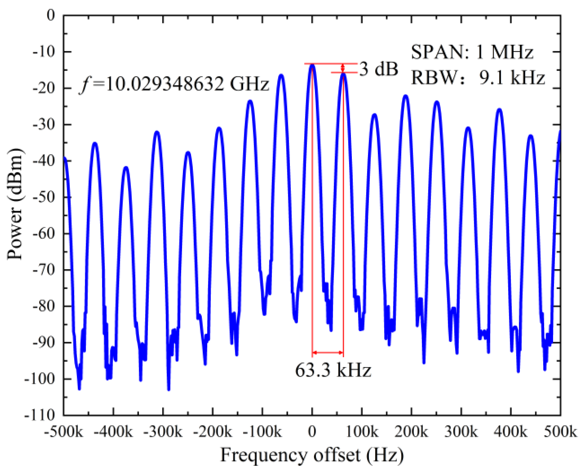
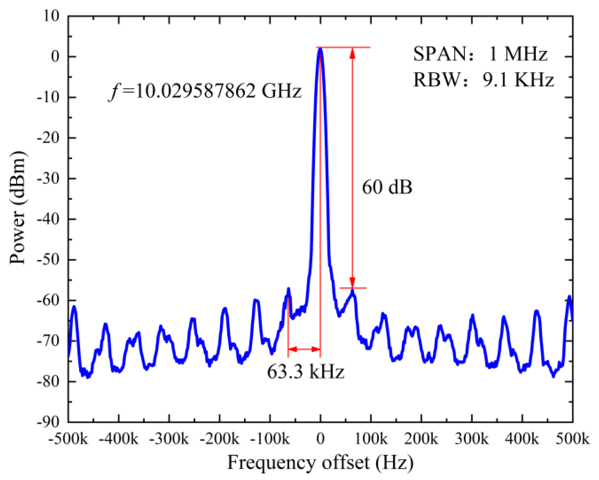
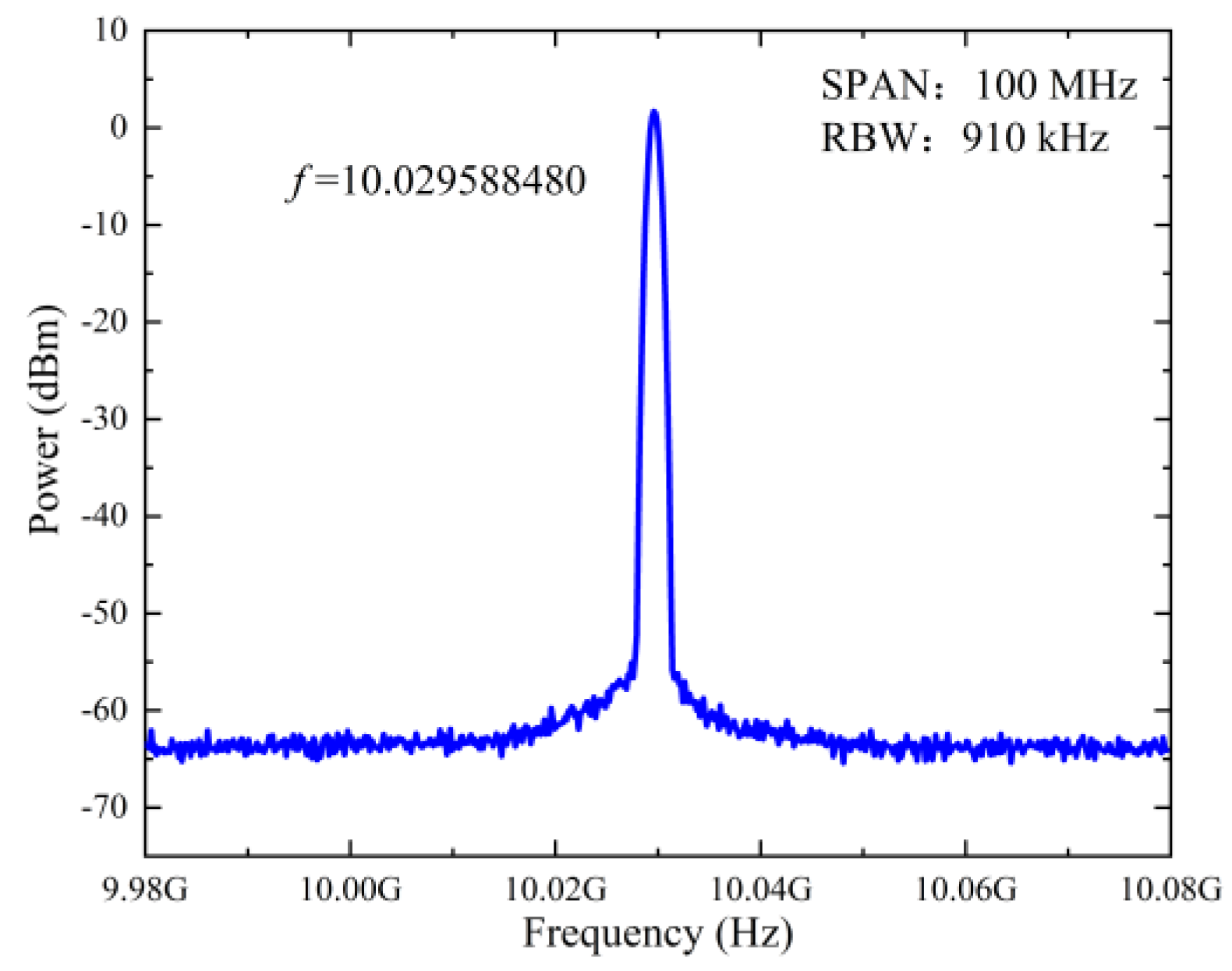
3. Experiment and Results

An experiment based on the setup shown in Figure 1a was performed. A distributed feedback laser diode (DFB-LD) acted as the signal laser (SL). The SL can emit continuous-wave light with 1549.920 nm, and the power is less than 20 dBm. A tunable laser (NKT Photonics Koheras AdjustiK) served as the pump laser (PL). The PL can emit continuous-wave light range from 1549.380 to 1550.475 nm. The tuning step of the PL was 0.001 nm and the power of the PL was less than 17 dBm. The DOMZM and MZM had 3-dB bandwidth of 20 GHz. The length of SMF was 1 km and the HNLF was 3 km. The PD1 had a 3-dB bandwidth of 18 GHz. The PD2 had a 3-dB bandwidth of 40 GHz. The EA1 and EA2 had 3-dB bandwidth of 18 GHz and gain of 30 dB.
To verify the performance of the proposed TOEO scheme, we did detailed research on the microwave power spectrum, phase noise and stability. As shown in Figure 1a, when the Loop1 was connected and the Loop2 was disconnected in the blue box, there was a single loop SBS-based TOEO, which was able to freely run. The generated 10 GHz microwave power spectrum of the single loop SBS-based OEO with 3 km Loop1 is shown in Figure 2; the SMSR was 3 dB and mode interval was 63.3 kHz. When Loop1 and Loop2 were both connected, there is a coupled dual-loop SBS-based TOEO, which combines the CDL and SBS. The generated 10 GHz microwave power spectrum of the coupled SBS-based TOEO with 3 km Loop1 and 1 km Loop2 is shown in Figure 3; the SMSR was 60 dB and mode interval was 63.3 kHz. Compared with the single loop SBS-based TOEO, the SMSR of the coupled dual-loop SBS-based TOEO had been improved by 57 dB. The measured 10 GHz microwave power spectrum of the coupled SBS-based TOEO with span of 100 MHz is shown in Figure 4. The 10 GHz signal generated almost realized single mode operation. The frequency tunability of the coupled SBS-based TOEO was then investigated by tuning the pump wave length of the pump laser. Figure 5 shows the superimposed spectrum of the generated signal with tunable frequency range from 2 to 18 GHz with a tuning step of 1 GHz.
To evaluate the phase noise performance, a comparison between the single loop SBS-based TOEO and the coupled dual-loop SBS-based TOEO was made. As shown in Figure 6, the 10 GHz microwave signal phase noise of the single loop SBS-based TOEO was −79.8 dBc/Hz at 10 kHz frequency offset. The 10 GHz microwave signal phase noise of the coupled dual-loop SBS-based TOEO was −95.2 dBc/Hz at 10 kHz frequency offset, which was 15.4 dB lower than that of the single loop SBS-based TOEO. The phase noise performance is sufficiently improved due to the use of the coupled dual-loop. As shown in Figure 7, when the oscillation frequency of the coupled dual-loop SBS-based TOEO was chosen as 5, 10, or 15 GHz, the phase noise was as low as −95 dBc/Hz at 10 kHz frequency offset.
The stability of the coupled dual-loop SBS-based TOEO was also investigated. Within the time duration of 30 min, the electrical spectrum of the generated signals were measured every 1 min. Figure 8 shows that the frequency drift at 10 GHz was within 0.3 ppm and the power drifts at 10 GHz was within 0.2 dB during 30 min.
It can be seen from above experimental results that the coupled dual-loop plays an important role in the performance improvement of SBS-based TOEO. The coupled dual-loop SBS-based TOEO shows great improvement in side mode, phase noise and stability over the single-loop SBS-based TOEO. The mode spacing of coupled dual-loop SBS-based TOEO was significantly different from that of ordinary dual-loop OEO. The mode interval of the ordinary dual-loop OEO in [11,12,13,14] was determined by two loops. But the mode interval of the coupled dual-loop TOEO was only determined by Loop1. The mode interval of coupled dual-loop TOEO was independent of the delay of Loop2. Because Loop1 and Loop2 were non-linearly coupled in the coupled dual-loop OEO, this asymmetric loop design allows the two loops to function differently. Loop1 acts as a main oscillation loop to determine the mode interval, while Loop2 acts as a slave oscillating loop to suppress spurious caused by multiplicative phase noise and link delay [23,24]. Therefore, compared with the ordinary dual-loop SBS-based TOEO and polarization-multiplexed dual-loop SBS-based TOEO proposed in [15,16], the coupled dual-loop SBS-based TOEO can improve the side-mode and stability, and the phase noise can also be further improved by using the high performance active devices in the link.

4. Conclusions

In this paper, a TOEO with CDL based on SBS was proposed and experimentally demonstrated. Experimental results verify that the coupled dual-loop plays an important role in the performance improvement of the SBS-based TOEO. The scheme effectively improves the side mode, phase noise and stability of the SBS-based TOEO. Experimental results show that microwave signals with a widely tunable range from 2 to 18 GHz are generated. The SMSR is superior to 60 dB and the phase noise is as low as −95 dBc/Hz at 10 kHz frequency offset. The frequency and power drifts at 10 GHz are within 0.3 ppm and 0.2 dB during 30 min, respectively. Compared with the single loop SBS-based TOEO, the ordinary dual-loop SBS-based TOEO and polarization-multiplexed dual-loop SBS-based TOEO, the performance of the coupled double-loop OEO can be further improved if using the high-performance active devices in the link.

Author Contributions

F.F. designed and set up the experiment; W.Z. and J.W. carried out the measurements under the supervision of J.H., Y.G., Z.W., X.H. and M.Z. provided the theoretical support for modelling the experiment. F.F. wrote the manuscript and all authors suggested improvements.

Funding

This work was supported by the National Natural Science Foundation of China under Grant 61704017 and 61605023, the Dalian Science and Technology Innovation Foundation under Grant 2018J11CY006, the Fundamental Research Funds under Grant DUT18LAB20, DUT18GF102 and DUT18ZD106.

Conflicts of Interest

The authors declare no conflict of interest.

References

  1. Yao, X.S.; Maleki, L. Optoelectronic microwave oscillator. J. Opt. Soc. Am. B 1996, 13, 1725–1735. [Google Scholar] [CrossRef]
  2. Ghelfi, P.; Laghezza, F.; Scotti, F.; Serafino, G.; Capria, A.; Pinna, S.; Onori, D.; Porzi, C.; Scaffardi, M.; Malacarne, A.; et al. A fully photonics-based coherent radar system. Nature 2014, 507, 341–345. [Google Scholar] [CrossRef] [PubMed]
  3. Chembo, Y.K. Laser-based optoelectronic generation of narrowband microwave chaos for radars and radio-communication scrambling. Opt. Lett. 2017, 42, 3431–3434. [Google Scholar] [CrossRef] [PubMed]
  4. Zou, X.H.; Liu, X.K.; Li, W.Z.; Li, P.X.; Pan, W.; Yan, L.S.; Shao, L.Y. Optoelectronic Oscillators (OEOs) to Sensing, Measurement, and Detection. IEEE J. Quantum Electron. 2016, 52. [Google Scholar] [CrossRef]
  5. Pan, S.L.; Yao, J.P. Wideband and frequency-tunable microwave generation using an optoelectronic oscillator incorporating a Fabry-Perot laser diode with external optical injection. Opt. Lett. 2010, 35, 1911–1913. [Google Scholar] [CrossRef] [PubMed]
  6. Tang, Z.Z.; Pan, S.L.; Zhu, D.; Guo, R.H.; Zhao, Y.J.; Pan, M.H.; Ben, D.; Yao, J.P. Tunable Optoelectronic Oscillator Based on a Polarization Modulator and a Chirped FBG. IEEE Photonics Technol. Lett. 2012, 24, 1487–1489. [Google Scholar] [CrossRef]
  7. Li, W.Z.; Yao, J.P. A Wideband Frequency Tunable Optoelectronic Oscillator Incorporating a Tunable Microwave Photonic Filter Based on Phase-Modulation to Intensity-Modulation Conversion Using a Phase-Shifted Fiber Bragg Grating. IEEE Trans. Microw. Theory Techn. 2012, 60, 1735–1742. [Google Scholar] [CrossRef]
  8. Xie, X.P.; Zhang, C.; Sun, T.; Guo, P.; Zhu, X.Q.; Zhu, L.X.; Hu, W.W.; Chen, Z.Y. Wideband tunable optoelectronic oscillator based on a phase modulator and a tunable optical filter. Opt. Lett. 2013, 38, 655–657. [Google Scholar] [CrossRef] [PubMed]
  9. Marpaung, D.; Morrison, B.; Pagani, M.; Pant, R.; Choi, D.Y.; Luther-Davies, B.; Madden, S.J.; Eggleton, B.J. Low-power, chip-based stimulated Brillouin scattering microwave photonic filter with ultrahigh selectivity. Optica 2015, 2, 76–83. [Google Scholar] [CrossRef]
  10. Kittlaus, E.A.; Otterstrom, N.T.; Rakich, P.T. On-chip inter-modal Brillouin scattering. Nat. Commun. 2017, 8. [Google Scholar] [CrossRef] [PubMed]
  11. Yao, X.S.; Maleki, L. Multiloop optoelectronic oscillator. IEEE J. Quantum Electron. 2000, 36, 79–84. [Google Scholar] [CrossRef]
  12. Jiang, Y.; Yu, J.L.; Wang, Y.T.; Zhang, L.T.; Yang, E.Z. An optical domain combined dual-loop optoelectronic oscillator. IEEE Photonics Technol. Lett. 2007, 19, 807–809. [Google Scholar] [CrossRef]
  13. Jia, S.; Yu, J.L.; Wang, J.; Wang, W.R.; Wu, Q.; Huang, G.B.; Yang, E.Z. A Novel Optoelectronic Oscillator Based on Wavelength Multiplexing. IEEE Photonics Technol. Lett. 2015, 27, 213–216. [Google Scholar] [CrossRef]
  14. Fan, F.; Hu, J.J.; Zhu, W.W.; Gu, Y.Y.; Han, X.Y.; Zhao, M.S. Dual-loop optoelectronic oscillator based on a compact balanced detection scheme. Opt. Eng. 2017, 56. [Google Scholar] [CrossRef]
  15. Peng, H.F.; Zhang, C.; Xie, X.P.; Sun, T.; Guo, P.; Zhu, X.Q.; Zhu, L.X.; Hu, W.W.; Chen, Z.Y. Tunable DC-60 GHz RF Generation Utilizing a Dual-Loop Optoelectronic Oscillator Based on Stimulated Brillouin Scattering. J. Lightw. Technol. 2015, 33, 2707–2715. [Google Scholar] [CrossRef]
  16. Han, X.Y.; Ma, L.; Shao, Y.C.; Ye, Q.; Gu, Y.Y.; Zhao, M.S. Polarization multiplexed dual-loop optoelectronic oscillator based on stimulated Brillouin scattering. Opt. Commun. 2017, 383, 138–143. [Google Scholar] [CrossRef]
  17. Zhang, Y.L.; Hou, D.; Zhao, J.Y. Long-Term Frequency Stabilization of an Optoelectronic Oscillator Using Phase-Locked Loop. J. Lightw. Technol. 2014, 32, 2408–2414. [Google Scholar] [CrossRef]
  18. Bogataj, L.; Vidmar, M.; Batagelj, B. A Feedback Control Loop for Frequency Stabilization in an Opto-Electronic Oscillator. J. Lightw. Technol. 2014, 32, 3690–3694. [Google Scholar] [CrossRef]
  19. Liu, J.L.; Liu, A.N.; Dai, J.; Zhang, T.; Xu, K. Generation and stabilization of millimeter-wave signal employing frequency-quadrupling phase-locked optoelectronic oscillator. In Proceedings of the SPIE Terahertz, RF, Millimeter, and Submillimeter-Wave Technology and Applications XI, San Francisco, CA, USA, 29 January–1 February 2018. [Google Scholar] [CrossRef]
  20. Li, H.W.; Daryoush, A.S.; Vilcot, J.P.; Decoster, D.; Chazelas, J.; Bouwmans, G.; Quiquempois, Y.; Deborgies, E. Improving thermal stability of opto-electronic oscillators. IEEE Microw. Mag. 2006, 7, 38–47. [Google Scholar] [CrossRef]
  21. Saleh, K.; Bouchier, A.; Merrer, P.H.; Llopis, O.; Cibiel, G. Fiber Ring Resonator Based Opto-Electronic Oscillator: Phase Noise Optimisation and Thermal Stability Study. In Proceedings of the SPIE 7936, RF and Millimeter-Wave Photonics, San Francisco, CA, USA, 22–27 January 2011. [Google Scholar]
  22. Peng, H.F.; Xu, Y.C.; Peng, X.F.; Zhu, X.Q.; Guo, R.; Chen, F.Y.; Du, H.Y.; Chen, Y.X.; Zhang, C.; Zhu, L.X.; et al. Wideband tunable optoelectronic oscillator based on the deamplification of stimulated Brillouin scattering. Opt. Express 2017, 25, 10287–10305. [Google Scholar] [CrossRef]
  23. Nguimdo, R.M.; Chembo, Y.K.; Colet, P.; Larger, L. On the Phase Noise Performance of Nonlinear Double-Loop Optoelectronic Microwave Oscillators. IEEE J. Quantum Electron. 2012, 48, 1415–1423. [Google Scholar] [CrossRef]
  24. Xu, W.; Jin, T.; Chi, H. Frequency multiplying optoelectronic oscillator based on nonlinearly-coupled double loops. Opt. Express 2013, 21, 32516–32523. [Google Scholar] [CrossRef]
Figure 1. (a) Schematic diagram of the the coupled dual-loop stimulated Brillouin scattering (SBS)-based tunable optoelectronic oscillator (TOEO). SL: signal laser; DOMZM: dual-output Mach–Zehnder intensity modulator; SMF: single mode fiber; PD, photodetector; MZM: Mach–Zehnder intensity modulator; ISO: optical isolator; HNLF, high non-linear fiber; OC: optical circulator; PL, pumped laser; PC, polarization controller; EA: electrical amplifier; ES, electrical splitter. (b) The spectrums at different point of the TOEO.
Applsci 09 02077 g001
Figure 2. The generated 10 GHz microwave power spectrum of the single loop SBS-based TOEO.
Applsci 09 02077 g002
Figure 3. The generated 10 GHz microwave power spectrum of the coupled dual-loop SBS-based TOEO.
Applsci 09 02077 g003
Figure 4. The generated 10 GHz microwave power spectrum of the coupled dual-loop SBS-based TOEO with span of 100 MHz.
Applsci 09 02077 g004
Figure 5. The generated signal spectrum with tunable frequency range from 2 GHz to 18 GHz.
Applsci 09 02077 g005
Figure 6. The 10 GHz microwave signal phase noise comparison between single loop SBS-based TOEO and the coupled dual-loop SBS-based TOEO.
Applsci 09 02077 g006
Figure 7. The 5, 10 and 15 GHz microwave signals phase noise of the coupled dual-loop SBS-based TOEO.
Applsci 09 02077 g007
Figure 8. (a) The frequency drift of the coupled dual-loop SBS-based TOEO at 10 GHz; (b) the power drift of the coupled dual-loop SBS-based TOEO at 10 GHz.
Applsci 09 02077 g008

