Featured Application
This work can good candidate for parameter estimation and channel equalization in elastic optical networks (EON).
Abstract
A joint compensation scheme based on pilot symbols aiding adaptive Kalman filter (AKF) for phase noise and polarization cross-talk is proposed and investigated via numerical simulation and experimental demonstration. In the proposed scheme, the optimizing parameter Q is adaptively adjusted according to signal parameters or channel conditions. This improvement avoids the drawback of conventional extended Kalman filter (EKF), and its performance is strongly dependent on Q. Another improvement is that the convergence speed of AKF is improved. Pilot quadrature phase shift keyin (QPSK) symbols are inserted into 16 quadrature amplitude modulation (QAM) signals periodically. Besides accelerating convergence speed, the employment of pilot symbols also improves the tracking capability of AKF. The format ratio between pilot symbols and payload symbols is suggested under different system environments, for instance, optical signal-to-noise rate, polarization rotation frequency drift rate, and laser linewidth. With the proposed scheme, it has excellent tolerance to initial parameter Q and dramatically improves the performances in convergence speed, polarization rotation frequency drift rate tracking, and carrier phase recovery. Both the numerical simulation and experimental demonstration achieve convergence improvement for around 40 times than the original AKF. Additionally, the improvements in tracking ability are also demonstrated.
1. Introduction
The recent evolution in information technology, such as 5G, Internet of Things, and big data [1,2,3], is promoting the growing and dynamic demands on bandwidth and capacity of optical data transmission. With the limited bandwidth provided by electrical devices, exploiting polarization multiplexing and higher-order modulation formats, for instance, 16QAM and 64QAM can increase the spectrum efficiency of transmission systems [4,5,6]. However, with higher-order modulation formats the system performance has less tolerance against carrier phase estimation error, and it is difficult to achieve fast convergence during compensating polarization misalignment. The conventional algorithm for carrier phase noise is the blind phase search (BPS) algorithm, which has the disadvantage of having high complexity [7,8]. Some efforts have been made to decrease the computational complexity [9,10]. Regarding polarization tracking, the traditional algorithms are the constant modulus algorithm (CMA) and its variants [11,12,13]. The CMA algorithm is capable of tracking polarization rotation of up to 1 Mrad/s [14], which is not enough for meeting the requirements imposed by dynamic or burst optical detection scenarios.
For coherent optical communication system, both polarization tracking and carrier phase recovery are essential. The algorithms that were mentioned above such as CMA+BPS can be used for polarization tracking and carrier phase recovery. While we also have another choice, the extended Kalman filter (EKF) has been demonstrated in coherent optical transmission systems [15,16,17,18,19]. This is a joint scheme and can be used for polarization tracking and carrier phase recovery simultaneously, the overall computational complexity is lower than CMA+BPS. However, it is commonly known that the tuning parameters’ Q value is significant for determining EKF performance. The higher laser linewidth, the larger Q value should be configured theoretically. The same rule exists in the case of tracking polarization rotation. Therefore, an adaptive Kalman filter (AKF) scheme is expected, in which Q value can change along with the conditions in an intelligent manner [20]. The convergence speed should be improved further in the case of high-order modulation format to meet the requirement of the next-generation dynamic optical transmission.
Based on our previous work [21], we make some improvements to AKF and investigate it via numerical simulation and experimental demonstrations. Firstly, the model of the adaptive Kalman filtering assisted by the pilot symbols is described, in which the Q value can be updated under dynamic network conditions. With the detailed simulation and experimental demonstration, the dependence of the scheme performance on pilot symbols parameters and operating conditions, including format ratio and phase noise, the polarization rotation frequency drift rate is investigated comprehensively. Finally, the convergence improvement and excellent tolerance against initial Q value are verified in the proposed scheme. Computational complexity analysis is carried out at the end.
2. Principle
As an example of illustration, in our proposed scheme, the signal frame structure is shown in Figure 1, QPSK signals are inserted into 16QAM signals in the time domain periodically. The reason for inserting QPSK signals lies in the benefits of faster convergence and better tracking performance. The combination of QPSK pilot symbols and higher-order modulation signals such as 16QAM or 64QAM can improve the overall system performance. Another critical parameter is power ratio (PR) between QPSK and 16QAM, and its investigation was carried out [22]. The power ratio between QPSK and 16QAM is set to be 6.5 dB. In this paper, we will conduct an investigation on 16QAM, 64QAM is not included in this paper. The reason is the limit of experimental conditions. We plan to investigate 64QAM in the next step further as soon as the conditions are improved.

Figure 1.
The frame structure of the combination of the pilot QPSK symbols and 16QAM symbols.
Assuming that chromatic dispersion, carrier frequency offset, and timing error have been compensated, the signals are only impaired by carrier phase noise and crosstalk between two polarizations. Therefore, the received signal is represented mathematically as follows:
where represent the received signals, the transmitted symbol, time-varying unitary polarization transformation matrix, carrier phase noise, and additive white Gaussian noise, respectively. Setting a fixed angular polarization rotation rate is a traditional way to simulate time-varying polarization. To evaluate the performance when dealing with the dynamic signal, we propose a time-varying polarization rotation rate method. The polarization rotation frequency drift rate is introduced, which is similar to acceleration. The polarization rotation under drift has the following expression:
, , , , describe the polarization rotation speed of symbol, initial polarization rotation speed, polarization rotation frequency drift rate, the corresponding time of symbol, and azimuth angle.
The resultant EKF model is described mathematically by the following set of equations:
Equations (4) and (6) are the measurement equation and state equation, respectively. , are measurement noise and process noise respectively. . There are five elements in this state vector. The first four elements are related to polarization, and the last one is the element related to phase noise. By using the information of state vector, the received signal is recovered. is the recovered signal, . We find the closest ideal constellation to as the desired output and is the residual measurement. Finally, by putting into the state update equations, the new state vector in the next time slot is updated.
The state update equations are listed as follows [15]:
The matrices and describe the process equation, process noise covariance, measurement noise covariance, error covariance, and Kalman gain, respectively. and represent the Jacobian matrix and innovation vector, respectively. In addition, the process noise covariance of carrier phase noise and polarization rotation can be expressed as . is the Q value related to polarization, and is the Q value related to the laser linewidth.
in EKF always plays an important role. For example, with the larger laser linewidth, which means a larger phase variation, the larger value is required to achieve better performance. A similar rule applies to polarization rotation along the fiber. Therefore, conventional EKF is difficult to ensure optimal performance with dynamic signals or time-varying fiber channel conditions. Additionally, an EKF is unstable if the initial noise covariance is not properly configured. Therefore, an adaptive approach is necessary to adjust the in an intelligent manner for dealing with dynamic conditions. This adaptation can be introduced with the following expression [20]:
Generally, the forgetting factor can be introduced in the following update equation to calculate . This operation can decrease the computational complexity. The forgetting factor α is usually set to be 0.975.
As shown in Equation (12), is dependent on The corresponding Q value, including and is also depending on it. With a larger , the higher Q value is led. In the initial stage of EKF, the residual measurement is large, and a high Q value is led. In the convergence stage of EKF, the residual measurement becomes small, and the Q value is small. In a dynamic network condition, the residual measurement will vary along with operating conditions. This means that the Q can respond to changing network conditions.
A switch mode is also employed for enhancing this response mechanism and it is shown in Figure 2. We define a threshold value . The average of measurement residual is calculated and compared with the threshold value. If the average of measurement residual is smaller than the threshold value, the Q value will be updated. If not, the Q value is set to the previous value. The above scheme can be schematically presented in the following diagram:
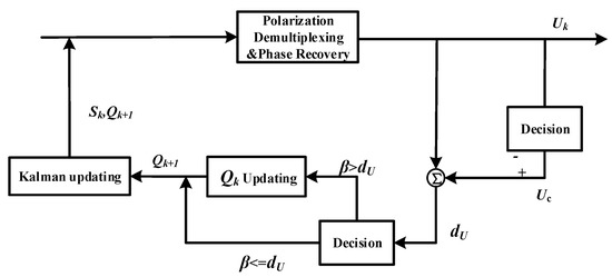
Figure 2.
The schematic diagram of the proposed adaptive Kalman filter scheme.
3. Results
3.1. Simulation Results
Firstly, the parameter optimization of the frame structure is discussed. The block length is 210, and the total length is 215. The power ratio between the QPSK and 16QAM is set as 6.5 dB, which can maximize the power efficiency [16]. The key parameter to be discussed in the following is the format ratio (FR). The FR between QPSK and 16QAM is set to {1:1 1:3 1:7} and the corresponding system symbol rate is 32.6 Gbaud, 28 Gbaud, and 26.13 Gbaud to obtain the same effective bit rate of 98 Gbit/s. Figure 3 depicts the bit error rate (BER) performance of AKF with pilot symbols within the optical signal to noise ratio (OSNR) range of 17–22 dB. The result shows that compared with pure 16QAM case, the OSNR sensitivity gain is around 1 dB at FR of 1:1. For FR = 1:3 and 1:7, the OSNR sensitivity gain is 0.5 dB and 0.35 dB, respectively. While FR = 1:1 has better performance, it will significantly decrease spectrum efficiency. Therefore, a higher device bandwidth is required. In the following, the systems with FR = 1:3 and 1:7 is only considered for acceptable spectrum efficiency.
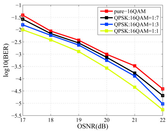
Figure 3.
OSNR-BER curves of different FR.
Taking the tracking performance into consideration in Figure 4a, the horizontal axis is the polarization rotation frequency drift rate, and the vertical axis is log10 (BER). The system target BER is 1 × 10⁻². With the increasing polarization rotation frequency drift rate, the performance at FR = 1:3 is the best, and the maximum tracking polarization rotation frequency drift rate is 220 rad/us2. The pure-16QAM demonstrates the worst performance, and the maximum tracking polarization rotation frequency drift rate is 74 rad/us2. With FR = 1:7, moderate performance is obtained and the allowable drift rate is 128 rad/us2. When it comes to the phase noise, the same conclusion is obtained from Figure 4b. The tolerable laser linewidth when FR = 1:3 is 10.7 MHz. The pure-16QAM system has the worst tolerance of 3.8 MHz. When FR = 1:7, the laser linewidth of 8.2 MHz can be tolerable. Now, we can conclude that with an increase in FR, the tracking performance is improved. In a practical situation, we need to get a good trade-off between the tracking ability and spectrum efficiency. In the case of desiring improvements on convergence and tracking with sacrificing spectrum resource at an acceptable level, the FR of 1:7 is preferred and adopted in the following discussion.
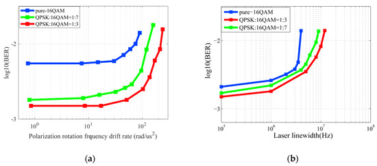
Figure 4.
(a) BER performance of FR = 1:3 and 1:7 compared with pure-16QAM of dynamic polarization rotation and (b) laser linewidth.
The convergence speed is evaluated by mean square error (MSE) of the recovered signals, which is presented in Figure 5. The polarization crosstalk is set to be pi/4, and laser linewidth is 100 kHz. With FR = 1:7, AKF with pilot symbols can converge within 50 symbols, and AKF without pilot symbols need around 2500-symbols to be stable.
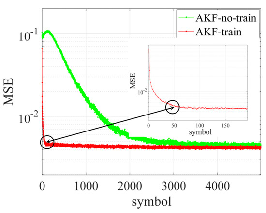
Figure 5.
The convergence curves of AKF.
The dynamic polarization rotation tolerance is investigated in Figure 6. With the polarization rotation frequency drift rate increasing, pilot AKF and EKF have different performance dependence on . The EKF is strongly dependent on . With smaller values, higher estimation accuracy is achieved with the penalty of reduced estimation range. The proposed pilot AKF with different have the same estimation accuracy and range, which indicates that there is no need to adjust the initial value manually under different application scenarios.
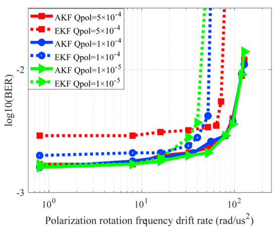
Figure 6.
Dynamic polarization rotation tolerance of AKF and EKF with pilot symbols.
In this part, the laser linewidth tolerance under a different Q value is carried out. Figure 7 presents the BER performance as a function of laser linewidth for AKF and EKF with different initial values. The result is similar to the polarization tracking case. EKF with a smaller value shows higher estimation accuracy and degraded estimation ranges. This means the laser linewidth tolerance is low, such as the target BER is 1 × 10⁻², when of EKF is 5 × 10⁻⁴, 1 × 10⁻⁴, and 1 × 10⁻⁵, the corresponding laser linewidth is about 3.5 MHz, 3 MHz, and 1.35 MHz, respectively. The AKF with pilot symbol scheme with a different value shows the same estimation accuracy and estimation ranges which is about 8.3 MHz. The proposed AKF with pilot symbol scheme is regardless of the initial value. This means that the proposed scheme can achieve optimal carrier recovery even with different laser linewidth within a wide allowable range of the initial .
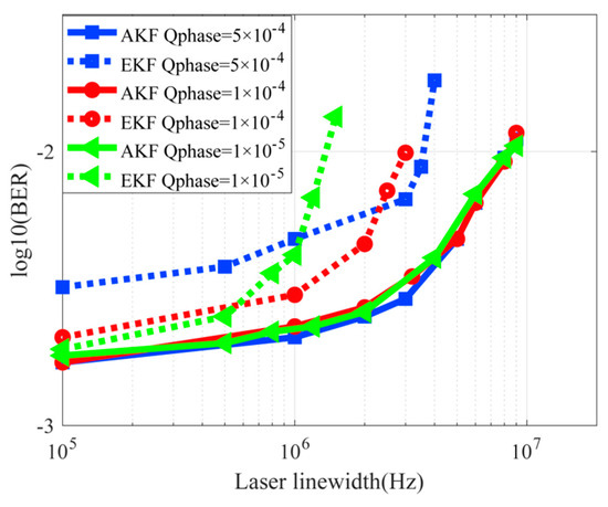
Figure 7.
Laser linewidth tolerance of AKF and EKF with pilot symbols.
The joint performance of pilot AKF with dynamic polarization rotation tracking and laser linewidth estimation is carried out by comparison with EKF. The system parameters in the simulation are set as follows: FR is 1:7, symbol rate is 26.13 Gbaud, OSNR is 19.5 dB, and the optimal R for EKF and AKF are found to be 0.25 I2×2 and 0.08 I2×2, respectively.
In practical applications, carrier phase noise and dynamic polarization rotation exists at the same time. and need to be set simultaneously. The BER performance of AKF and EKF with pilot symbols is plotted as a function of and in Figure 8. The laser linewidth is set to be 2 MHz, and the polarization rotation rate is set to be 10 M rad/s. and is scanned from 10−5 to 5 × 10⁻⁴. As shown in Figure 8a, the BER of EKF is changed from 2.1 × 10⁻³ to 0.25. When = 10−5 and = 3 × 10⁻⁵, it achieves the best performance. Figure 8b shows the BER performance of the AKF with pilot symbols scheme and the BER fluctuation can be negligible and has the range from 2.2 × 10⁻³ to 3.2 × 10⁻³. Therefore, the advantage of the AKF with the pilot symbol scheme and the conventional EKF is obvious. The former can achieve almost the same performance regardless of the initial value of and , which means the performances do not rely on the initial value and the update of these two parameters are adjusted adaptively and simultaneously.
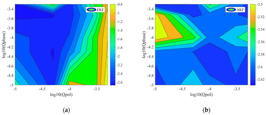
Figure 8.
(a) The influence of and value of EKF with pilot symbols and (b) AKF with pilot symbols.
3.2. Experimental Results
The pilot symbol-aided AKF scheme is experimentally studied in a 10 Gbaud Dual-polarization 16QAM system, as shown in Figure 9. In the transmitter, an arbitrary waveform generator (AWG7122C, Tektronix, Portland, Oregon, USA) is used to generate electrical signals to drive an optical I/Q modulator. The optical carrier from a 100 kHz narrow linewidth laser is divided into two parts by a 3 dB coupler. One part of the light is fed into the optical modulator. The other part is used as a local oscillator for coherent detection. The length of the signal fiber link is 10 km. In the receiver, the electrical signal after coherent detection is sampled by a digital serial analysis with 50 GSa/s (DSA72004C). Finally, the sampled data is processed by an offline digital signal processor (DSP), including timing recovery and frequency offset estimation based on maximum fast Fourier transform (Max-FFT). The dynamic polarization rotation is also digitally achieved in the DSP section by the polarization matrix, which is mentioned in Equations (2) and (3).
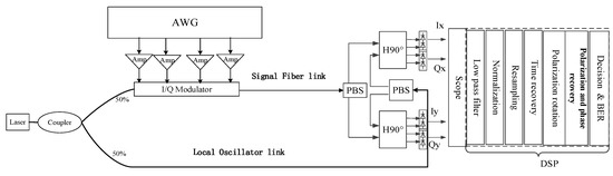
Figure 9.
Experimental setup of 16QAM coherent optical communication system.
Firstly, the convergence performance is described by the curves of the estimated {a,b,c,d}, as shown in Figure 10. Two data structures are used to evaluate the convergence performance of AKF: pilot symbols and non-pilot symbols. As shown in Figure 10a, AKF with pilot symbols can achieve a stable estimation within 20 symbols, which is attributed to the quick acquisition capability of AKF with pilot symbols. However, AKF without pilot symbols requires more than 800 symbol periods to achieve high accuracy and stable estimation of the state vector in AKF, as depicted in Figure 10b. The experimental results confirm that the quick tracking capability is achieved by the aid of pilot symbols in the AKF scheme.
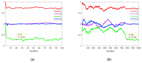
Figure 10.
(a) The convergence curves of AKF with pilot symbols and (b) convergence curves of AKF without pilot symbols.
In the following, the tracking capability of AKF with pilot symbols is investigated under dynamic polarization rotation rates. The format ratio and the dynamic polarization rotation rate are set to 1:7 and 6.1 rad/us2, respectively. As shown in Figure 11a, the estimated state vector {a,b,c,d} is changed synchronously with the applied time-varying polarization rotation rate. Meanwhile, is adjusted in an adaptive manner, which ensures that the AKF scheme can track the accelerating polarization rotation rate. It can be seen in Figure 11b that after the convergence is achieved, after around 5000 symbols, the tuning parameter increases basically. This is consistent with the accelerated rotation.
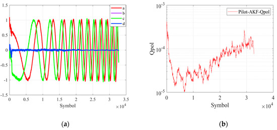
Figure 11.
(a) The curves of {a,b,c,d} and (b) adaptive parameter .
In Figure 12, the system target BER is set to 10−2. With the increasing polarization rotation frequency drift rate, the performance of FR = 1:7 is better than pure-16QAM. The allowable polarization rotation frequency drift rates under FR = 1:7 are 28.6 rad/us2. The improvement of tracking performance by 53% is obtained compared with the pure-16QAM case. The result shows that the improvement of tracking capability is successfully achieved by employing less pilot symbols in the proposed scheme.
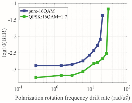
Figure 12.
BER performance of FR = 1:7 compared with pure-16QAM of dynamic polarization rotation.
Finally, the verification of tracking the performance of AKF with pilot symbols is carried out under a fixed rotation rate, which is compared with EKF. In Figure 13, AKF and EKF with pilot symbols have different performance dependence on . The performance of EKF relies on . High estimation accuracy is achieved with reduced estimation range when the is small, and low estimation accuracy is achieved with high estimation range when the is large. The proposed AKF with pilot symbols with different shows the same estimation accuracy and range.
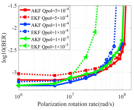
Figure 13.
Polarization rotation tracking performance of AKF and EKF with pilot symbols.
3.3. The Computational Complexity Analysis
Computational complexity is an important factor for measuring the performance of the scheme. So we calculate and compare the complexities of our scheme with that of CMA+BPS, the result is shown in Table 1. The calculation includes four categories: comparison, real multiplications, real additions, and look-up table (LUT) operations. M is the number of taps, and N is the block length. B is the number of test phases. When M is 11, N is 20, and B is 32. The CMA+BPS method needs 4112 real multiplications, 4030 real additions, and 32 comparisons, whereas the proposed joint scheme only needs 585 real multiplications, 459 real additions and 32 LUT operations. It should also be noted that the complexity of LUT is much less than that of real multiplication or addition. We can also conclude that for each symbol, the computational complexity of the proposed joint scheme is lower than that of CMA+BPS.

Table 1.
The calculation comparisons between our joint scheme and CMA+BPS.
4. Conclusions
In this paper, we proposed and demonstrated a carrier phase recovery and polarization tracking scheme. This scheme is based on adaptive Kalman filter aided by pilot symbols. Compared with the algorithm that we mentioned in the introduction, such as EKF and AKF without the pilot symbols, this new scheme has advantages in high convergence speed, tolerance to initial Q value, and improvements of tracking performance. Simulations and experiments have investigated all this.
In the simulation part, the optimal FR is suggested regarding OSNR sensitivity, dynamic polarization rotation, and laser linewidth. The tradeoff between tracking ability improvements and spectrum efficiency determines the optimal FR. Then the convergence speed is evaluated by MSE. AKF with pilot symbols can converge within 50 symbols, and AKF without pilot symbols achieves convergence within 2500 symbols. The investigations about the tolerance to initial Q value, including and are carried out. The results show that AKF has a high tolerance to initial parameter Q. It achieves almost the same tracking performance for different initial Q while EKF is exclusively relying on Q.
In the experiment part, we choose FR=1:7 to verify the improvements in convergence speed and tracking ability. AKF with pilot symbols can converge within 20 symbols, and AKF without pilot symbols achieves convergence within 800 symbols. In the following, the tracking performance improvement of dynamic polarization rotation is proved by the result of the experiment.
Finally, we also compare our scheme with CMA+BPS. The result shows that the calculation complexity is lower than that of CMA+BPS. In conclusion, the proposed scheme can be considered a good candidate for parameter estimation and channel equalization in the next generation of flexible and dynamic optical communication networks.
Author Contributions
Investigation, J.C., Y.Y., Q.X. and Q.Z.; Methodology, Q.X.; Writing—original draft, J.C.; Writing—review & editing, Y.Y., Q.Z., L.F., and Y.Y.
Funding
This work was supported by the National Natural Science Foundation of China (Contract No. 61205046 and 61575051) and Shenzhen Municipal Science and Technology Plan Project (JCYJ20150327155705357, KQCX2015032409501296, JSGG20150529153336124 and JCYJ20150529114045265).
Conflicts of Interest
The authors declare no conflict of interest.
References
- Hsiao, W.H.; Huang, C.C. A novel 5G TDD cellular system proposal based on multipath division multiple access. In Proceedings of the 2017 19th International Conference on Advanced Communication Technology (ICACT), PyeongChang, Korea, 19–22 February 2017. [Google Scholar]
- Hu, P.; Ning, H.; Qiu, T.; Song, H.; Wang, Y.; Yao, X. Security and Privacy Preservation Scheme of Face Identification and Resolution Framework Using Fog Computing in Internet of Things. IEEE Internet Things J. 2017, 4, 1143–1155. [Google Scholar] [CrossRef]
- Yang, W.; Wang, M.; Zhang, J.; Zou, J.; Hua, M.; Xia, T.; You, X. A novel 5G TDD cellular system proposal based on multipath division multiple access. Wirel. Commun. 2017, 24, 138–145. [Google Scholar] [CrossRef]
- Hongo, J.; Kasai, K.; Yoshida, M.; Nakazawa, M. 1-Gsymbol/s 64-QAM Coherent Optical Transmission Over 150 km. Photonics Technol. Lett. 2007, 19, 638–640. [Google Scholar] [CrossRef]
- Zhang, J.; Yu, J.; Chi, N.; Li, F.; Li, X. Experimental demonstration of 24-Gb/s CAP-64QAM radio-over-fiber system over 40-GHz mm-wave fiber-wireless transmission. Opt. Express 2013, 21, 26888–26895. [Google Scholar] [CrossRef] [PubMed]
- Jia, Z.; Chien, H.C.; Zhang, J.; Dong, Z.; Cai, Y. Performance Analysis of Pre- and Post-Compensation for Bandwidth-Constrained Signal in High-Spectral-Efficiency Optical Coherent Systems. In Proceedings of the Optical Fiber Communications Conference and Exhibition 2014, San Francisco, CA, USA, 9–13 March 2014. [Google Scholar]
- Zhang, Q.; Wang, M.G. Performance Analysis of Carrier Phase Estimation Algorithm for Coherent Optical Communication System. Electro-Opt. Technol. Appl. 2016, 6, 39–46. [Google Scholar]
- Zhou, X.; Zhong, K.; Gao, Y.; Lu, C.; Lau, A.P.T.; Long, K. Modulation-format-independent blind phase search algorithm for coherent optical square M-QAM systems. Opt. Express 2014, 22, 24044–24054. [Google Scholar] [CrossRef] [PubMed]
- Navarro, J.R.; Kakkar, A.; Schatz, R.; Pang, X.; Ozolins, O.; Udalcovs, A.; Popov, S.; Jacobsen, G. Efficient carrier phase recovery using BPS with angular quantization noise mitigation. Photonics 2017, 4, 37. [Google Scholar] [CrossRef]
- Navarro, J.R.; Udalcovs, A.; Pang, X.; Ozolins, O.; Kakkar, A.; Schatz, R.; Nordwall, F.; Popov, S.; Acobsen, G. High phase noise tolerant circular-64QAM with efficient phase recovery for coherent optical systems. In Proceedings of the Asia Communications and Photonics Conference 2017, Guangzhou, China, 10–13 November 2017. [Google Scholar]
- Louchet, H.; Kuzmin, K.; Richter, A. Improved DSP algorithms for coherent 16-QAM transmission. In Proceedings of the 34th European Conference on Optical Communication 2008, Brussels, Belgium, 21–25 September 2008. [Google Scholar]
- Lau, A.P.T.; Gao, Y.; Sui, Q.; Wang, D.; Lu, C. Beyond 100 Gb/s: Advanced DSP Techniques Enabling High Spectral Efficiency and Flexible Optical Communications. In Proceedings of the Asia Communications and Photonics Conference 2013, Beijing, China, 12–15 November 2013. [Google Scholar]
- Savory, S.J. Digital Coherent Optical Receivers: Algorithms and Subsystems. J. Sel. Top. Quantum Electron. 2010, 16, 1164–1179. [Google Scholar] [CrossRef]
- Savory, S.J. Digital filters for coherent optical receivers. Opt. Express 2008, 16, 804–817. [Google Scholar] [CrossRef] [PubMed]
- Marshall, T.; Szafraniec, B.; Nebendahl, B. Kalman filter carrier and polarization-state tracking. Opt. Lett. 2010, 35, 2203–2205. [Google Scholar] [CrossRef] [PubMed]
- Jiang, W.; Yang, Y.; Zhang, Q.; Sun, Y.; Zhong, K.; Zhou, X.; Yao, Y. Application of Kalman filter in frequency offset estimation for coherent optical quadrature phase-shift keying communication system. Opt. Eng. 2016, 55, 096102. [Google Scholar] [CrossRef]
- Cao, G.; Yang, Y.; Wang, F.; Cui, L.; Ning, R.; Gu, J.; Yao, Y. Extended Kalman based polarization and carrier phase quickly tracking for PDM-16QAM. Acta Opt. Sin. 2014, 53–58. [Google Scholar] [CrossRef]
- Cao, G.; Yang, Y.; Zhong, K.P.; Cui, L.; Ning, R.; Gu, J.; Yao, Y. Assessment of Extended Kalman Filtering Based Simultaneous Polarization and Phase Tracking for PDM-16QAM. In Proceedings of the Asia Communications and Photonics Conference 2014, Shanghai, China, 11–14 November 2014. [Google Scholar]
- Zhang, Q.; Yang, Y. Joint polarization tracking and channel equalization based on radius-directed linear Kalman filter. Opt. Commun. 2018, 407C, 142–147. [Google Scholar] [CrossRef]
- Xiang, Q.; Yao, Y. Fast, accurate, and robust frequency offset estimation based on modified adaptive Kalman filter in coherent optical communication system. Opt. Eng. 2017, 56, 096109. [Google Scholar]
- Xiang, Q.; Yang, Y.; Zhang, Q.; He, Q.; Yao, Y. Adaptive Kalman filter for polarization and phase recovery in wide ranges of optical signal-to-noise ratio, polarization rotation frequency, and laser linewidth. Opt. Eng. 2018, 57, 066107. [Google Scholar] [CrossRef]
- Jiang, W.; Yang, Y.; Cao, G.; Zhong, K.; Yao, Y. Blind and Simultaneous Polarization and Phase Recovery for Time Domain Hybrid QAM Signals Based on Extended Kalman Filtering. In Proceedings of the Asia Communications and Photonics Conference 2015, Hong Kong, China, 19–23 November 2015. [Google Scholar]
© 2018 by the authors. Licensee MDPI, Basel, Switzerland. This article is an open access article distributed under the terms and conditions of the Creative Commons Attribution (CC BY) license (http://creativecommons.org/licenses/by/4.0/).